US1663295A - Brake - Google Patents
Brake Download PDFInfo
- Publication number
- US1663295A US1663295A US206184A US20618427A US1663295A US 1663295 A US1663295 A US 1663295A US 206184 A US206184 A US 206184A US 20618427 A US20618427 A US 20618427A US 1663295 A US1663295 A US 1663295A
- Authority
- US
- United States
- Prior art keywords
- brake
- springs
- arm
- movable arm
- shoes
- Prior art date
- Legal status (The legal status is an assumption and is not a legal conclusion. Google has not performed a legal analysis and makes no representation as to the accuracy of the status listed.)
- Expired - Lifetime
Links
Images
Classifications
-
- F—MECHANICAL ENGINEERING; LIGHTING; HEATING; WEAPONS; BLASTING
- F16—ENGINEERING ELEMENTS AND UNITS; GENERAL MEASURES FOR PRODUCING AND MAINTAINING EFFECTIVE FUNCTIONING OF MACHINES OR INSTALLATIONS; THERMAL INSULATION IN GENERAL
- F16D—COUPLINGS FOR TRANSMITTING ROTATION; CLUTCHES; BRAKES
- F16D65/00—Parts or details
- F16D65/02—Braking members; Mounting thereof
- F16D65/04—Bands, shoes or pads; Pivots or supporting members therefor
- F16D65/08—Bands, shoes or pads; Pivots or supporting members therefor for internally-engaging brakes
-
- F—MECHANICAL ENGINEERING; LIGHTING; HEATING; WEAPONS; BLASTING
- F16—ENGINEERING ELEMENTS AND UNITS; GENERAL MEASURES FOR PRODUCING AND MAINTAINING EFFECTIVE FUNCTIONING OF MACHINES OR INSTALLATIONS; THERMAL INSULATION IN GENERAL
- F16D—COUPLINGS FOR TRANSMITTING ROTATION; CLUTCHES; BRAKES
- F16D2125/00—Components of actuators
- F16D2125/18—Mechanical mechanisms
- F16D2125/20—Mechanical mechanisms converting rotation to linear movement or vice versa
- F16D2125/22—Mechanical mechanisms converting rotation to linear movement or vice versa acting transversely to the axis of rotation
- F16D2125/28—Cams; Levers with cams
- F16D2125/30—Cams; Levers with cams acting on two or more cam followers, e.g. S-cams
Definitions
- This invention relates tobrakes and is illustrated as embodied in an internal ex anding brake -for an automobile.
- An object of the invention is to balance the return springs acting on the shoes or equivalent friction parts by the provision of novel means which can readily be adjusted without the use of an measuring instruments or the like.
- the springs are con: nected to an angularly movable arm which shifts itself to balance the pressure of the springs when the brake is ap lied and'which is then clamped firmly in a justed position to prevent further shlftin I
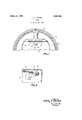
- Figure 1 is a partial vertical section through the upper part of the brake just inside the head of the brake drum and showing the brake shoes i1 side elevation; and Figure 2 is a perspective of the aboveiiescribed movable arm and its mounting.
- the brake includes a rotatable drum. 10, at the open side of which is arranged a back- 30 ing plate 12 and within which, is arran the friction means of the brake.
- the friction means ' is illustrated as including brake shoes 14 forced against the drum by means] 192?. Serial No.,206,184.
- the springs are connected to an angularly movable arm 22 having a bolt or stem 24- projectin through a slot 26 in the backing plate.
- the brake is applied, as for example by turning the cam 16, the springs 18 and 20 will turn the arm 22 until the pressures are balanced, and while the brake is held'so applied a.
- nut 28 is tightened up on the bolt or stem 24 to secure it firmly in place in its adjusted position, thus preserving the balancing of the springs 18 and 20. .50 While' one illustrative embodiment has been described in detail, it is not my intentionto limit'the scope of the invention to that particular embodiment or otherwise than by the terms of the appended claims. 5 I claim: a
- a brake comprising oppositely-movable friction parts, in combination with a spring resisting movement of each of said arts, an angularly' movable arm to which'sai springs are connected and which is shifted to balance the springs by application of the brake, and means for securing said arm with the springs balanced, to prevent it from shifting further.
- a brake comprising oppositely-movable 66 friction parts, in combination with a spring resisting movement of each of said parts,
- the present invent on relates to the balancing of springs 18 and 20 so that they will act on the shoes 14 or their equivalents with ed y e of the arm. 1
Landscapes
- Engineering & Computer Science (AREA)
- General Engineering & Computer Science (AREA)
- Mechanical Engineering (AREA)
- Braking Arrangements (AREA)
Description
A. Y. DODGE BRAKE Filed July 1e,' 192v INVENTOR ADlE l -Y. Done:
ATTORNEY Patented Mar. 20, 1928. l
UNITED STATES PATENT OFFICE.
iamnr. Y. nonen, or sou'rn BEND, INDIANA, AssIeNo'n TO namarx BRAKE comm, or cnrcaeo, ILLINOIS, A. CORPORATION or ILLmoIs.
BRAKE.
Application filed July 16,
This invention relates tobrakes and is illustrated as embodied in an internal ex anding brake -for an automobile. An object of the invention is to balance the return springs acting on the shoes or equivalent friction parts by the provision of novel means which can readily be adjusted without the use of an measuring instruments or the like. Pre erably the springs are con: nected to an angularly movable arm which shifts itself to balance the pressure of the springs when the brake is ap lied and'which is then clamped firmly in a justed position to prevent further shlftin I The above andother ob ects and features of the invention, including various novel and desirable details of construction, will be apparent from the following description of one illustrative embodiment shown in the accompanying drawing, in which:
Figure 1 is a partial vertical section through the upper part of the brake just inside the head of the brake drum and showing the brake shoes i1 side elevation; and Figure 2 is a perspective of the aboveiiescribed movable arm and its mounting.
In the arrangement selected for illustration the brake includes a rotatable drum. 10, at the open side of which is arranged a back- 30 ing plate 12 and within which, is arran the friction means of the brake. The friction means 'is illustrated as including brake shoes 14 forced against the drum by means] 192?. Serial No.,206,184.
equal force. Preferably the springs are connected to an angularly movable arm 22 having a bolt or stem 24- projectin through a slot 26 in the backing plate. %Vhen the brake is applied, as for example by turning the cam 16, the springs 18 and 20 will turn the arm 22 until the pressures are balanced, and while the brake is held'so applied a. nut 28 is tightened up on the bolt or stem 24 to secure it firmly in place in its adjusted position, thus preserving the balancing of the springs 18 and 20. .50 While' one illustrative embodiment has been described in detail, it is not my intentionto limit'the scope of the invention to that particular embodiment or otherwise than by the terms of the appended claims. 5 I claim: a
1. A brake comprising oppositely-movable friction parts, in combination with a spring resisting movement of each of said arts, an angularly' movable arm to which'sai springs are connected and which is shifted to balance the springs by application of the brake, and means for securing said arm with the springs balanced, to prevent it from shifting further.
2. A brake comprising oppositely-movable 66 friction parts, in combination with a spring resisting movement of each of said parts,
ged anangularly movable arm to which said sprin are connected and which is shifted to b ance the' springs .by application of the brake, and a clamping bolt and nut ada ted such as a double cam 16=against theresist- 'to be tightenedtoprevent further shi ting 35 ance of return springs 18 and 20. v
The present invent on relates to the balancing of springs 18 and 20 so that they will act on the shoes 14 or their equivalents with ed y e of the arm. 1
In testimony whereof, I have hereunto
Priority Applications (1)
| Application Number | Priority Date | Filing Date | Title |
|---|---|---|---|
| US206184A US1663295A (en) | 1927-07-16 | 1927-07-16 | Brake |
Applications Claiming Priority (1)
| Application Number | Priority Date | Filing Date | Title |
|---|---|---|---|
| US206184A US1663295A (en) | 1927-07-16 | 1927-07-16 | Brake |
Publications (1)
| Publication Number | Publication Date |
|---|---|
| US1663295A true US1663295A (en) | 1928-03-20 |
Family
ID=22765316
Family Applications (1)
| Application Number | Title | Priority Date | Filing Date |
|---|---|---|---|
| US206184A Expired - Lifetime US1663295A (en) | 1927-07-16 | 1927-07-16 | Brake |
Country Status (1)
| Country | Link |
|---|---|
| US (1) | US1663295A (en) |
Cited By (1)
| Publication number | Priority date | Publication date | Assignee | Title |
|---|---|---|---|---|
| US3572476A (en) * | 1968-01-26 | 1971-03-30 | Dba Sa | Shoe retracting system for internal shoe drum brakes, and brakes including same |
-
1927
- 1927-07-16 US US206184A patent/US1663295A/en not_active Expired - Lifetime
Cited By (1)
| Publication number | Priority date | Publication date | Assignee | Title |
|---|---|---|---|---|
| US3572476A (en) * | 1968-01-26 | 1971-03-30 | Dba Sa | Shoe retracting system for internal shoe drum brakes, and brakes including same |
Similar Documents
| Publication | Publication Date | Title |
|---|---|---|
| US3186521A (en) | Automatic adjusting devices for brake actuating mechanisms | |
| US2372415A (en) | Fluid-actuated brake | |
| US1663295A (en) | Brake | |
| US2459040A (en) | Tripod head | |
| US2639195A (en) | Brake drum vibration damper | |
| US2095753A (en) | Brake | |
| US2311765A (en) | Brake | |
| US2298007A (en) | Hydraulic actuator | |
| US2374859A (en) | Brake mechanism | |
| US2219764A (en) | Brake | |
| US2084388A (en) | Brake | |
| US1648185A (en) | Brake anchor | |
| US2313431A (en) | Brake | |
| US2562354A (en) | Adjusting means for brakes | |
| US2206628A (en) | Automatic adjuster | |
| US1936943A (en) | Brake | |
| US2298396A (en) | Hydraulic shock absorber valving assembly | |
| GB487316A (en) | Improvements in or relating to internal shoe brakes | |
| US1875000A (en) | Brake | |
| US2152105A (en) | Brake | |
| US1874928A (en) | Brake | |
| GB348013A (en) | Device for transmitting stresses by fluids compressible or not | |
| US1397430A (en) | Brake | |
| US1856070A (en) | Brake | |
| US2236473A (en) | Drum brake |