US166328A - Improvement in book-backing machines - Google Patents
Improvement in book-backing machines Download PDFInfo
- Publication number
- US166328A US166328A US166328DA US166328A US 166328 A US166328 A US 166328A US 166328D A US166328D A US 166328DA US 166328 A US166328 A US 166328A
- Authority
- US
- United States
- Prior art keywords
- book
- backing
- lever
- roll
- plate
- Prior art date
- Legal status (The legal status is an assumption and is not a legal conclusion. Google has not performed a legal analysis and makes no representation as to the accuracy of the status listed.)
- Expired - Lifetime
Links
- 230000003534 oscillatory effect Effects 0.000 description 4
- 241001125879 Gobio Species 0.000 description 2
- 230000002459 sustained effect Effects 0.000 description 2
- 238000005452 bending Methods 0.000 description 1
- 238000000034 method Methods 0.000 description 1
- 239000007787 solid Substances 0.000 description 1
Images
Classifications
-
- B—PERFORMING OPERATIONS; TRANSPORTING
- B42—BOOKBINDING; ALBUMS; FILES; SPECIAL PRINTED MATTER
- B42C—BOOKBINDING
- B42C5/00—Preparing the edges or backs of leaves or signatures for binding
- B42C5/02—Preparing the edges or backs of leaves or signatures for binding by rounding or backing
Definitions
- the invention relates to that class of machines used in the process of binding books where the several signatures which go to make up'the book are placed in their regular order and sewed together.
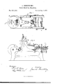
- the required curvature if any is desired, is given to the front edges when the rear edges are rolled and compressed, so as to form the back with projecting edges to furnish a support for the boards which form the covers, and to strengthen the back by making it solid; and it consists in certain improved means for holding the book or signature while being operated upon, and in an oscillating lever carrying the backingroll, sustained by a swinging fulcrum, together with the mechanism for operating the same, which will be more fully described hereafter, reference being made to the accompanying drawings, thrilling part of this specification, in which- Figure l is a plan or top view of the machine, and Fig. 2 is a longitudinal section of the same.
- A is the frame supporting the mechanism, and it may be made ot' any substantial inaterial.
- On the other end of this shaft is a cog-wheel, D, which gears with the wheel E on the shaft F.
- the bent arm G is attached to the wheel E by an adadjustable sliding plate, g, so that the motion thereof may be controlled, the other end being connected with the rocking plate H, which is pivoted to the main frame ath, and forms a swinging fulcrum for the oscillating lever carrying the backing-roll.
- .oscillating lever is attached the spring-plate r, made adjustable by the thumb-screw r', so that the backing-roll may give a little, to overcome any inequality in the book.
- U is a table, sliding in lgrooves in the main frame,
- the plate X is provided with notches, into which the spring locking-pin t, or some equivalent device, enters to hold the plate in the proper position for the operation of the backing-roller.
- the operation ot' my machine is as follows: The book is placed between the jaws c b, and securelyv clamped by the cam-lever c, the jaw a being adjusted to tit the size of the book. The Vframe X is then rotated on the gudgeon to bring the book under the backing-roller T, when the locking-pin t enters the notch, as before described. The sliding frame-U is then adjusted by means of the screws V, so as to bring the center of the book under the backing-roll when in the center of the are through which it moves.
- the bent arm G is adjusted, by means ot' the sliding plate g, to give the rocking fulcrum H a motio ⁇ n corresponding to the width of the book, producing a back-and-forth movement of the backing-roll T.
- a double oscillatory movement is given to the lever R, carrying the roll T.
- the shape ofthe cam I is such that the pressure of' the roll will be the least when over the center of' the book, and increase as it moves toward the sides.
- the arm Q is provided with holes, so that the oscillating lever may be adj usted for varying-sized books7 and the arm J, being hung in the sliding frame L, admits of very nice adjustment of the same by means of the screw.
- the backingroll By means of the cam-lever P. which may be operated by hand, or otherwise, the backingroll may be raised out of contact with the book, so that the plate X may be rotated to bring the book into position without stopping the machine.
Landscapes
- Engineering & Computer Science (AREA)
- Mechanical Engineering (AREA)
- Feeding Of Articles By Means Other Than Belts Or Rollers (AREA)
Description
l. ABMSTBUNGK.
Book-Backing Machine.
Patented Aug. 3,1875.
lllllf NPETERS, Frior-UTHGGRAPHER. wAsHmGTDN, D. C.
UNITED STATES PATENT OEETGE.
JAMES ARMSTRONG, OF CAMBRIDGE, MASSACHUSETTS.
IMPROVEMENT IN BOOK-BACKING MACHINES.
Specification forming part of Letters Patent No. 166.328, dated August 3, 1875; application filed May 21, 1875.
To all whom itmag/ concern:
Be it known that I, JAMEs ARMSTRONG, of the city ot Cambridge, Middlesex county, Massach usetts, have invented a new and Improved Book-Backing Machine, of which the following is a specitication The invention relates to that class of machines used in the process of binding books where the several signatures which go to make up'the book are placed in their regular order and sewed together. The required curvature, if any is desired, is given to the front edges when the rear edges are rolled and compressed, so as to form the back with projecting edges to furnish a support for the boards which form the covers, and to strengthen the back by making it solid; and it consists in certain improved means for holding the book or signature while being operated upon, and in an oscillating lever carrying the backingroll, sustained by a swinging fulcrum, together with the mechanism for operating the same, which will be more fully described hereafter, reference being made to the accompanying drawings, thrilling part of this specification, in which- Figure l is a plan or top view of the machine, and Fig. 2 is a longitudinal section of the same.
Like letters of reference refer to the same parts.
A is the frame supporting the mechanism, and it may be made ot' any substantial inaterial. Bis the drive-wheel on the shaft C. to which power may be applied in any convenient manner, as by hand or belts. On the other end of this shaft is a cog-wheel, D, which gears with the wheel E on the shaft F. 'The bent arm G is attached to the wheel E by an adadjustable sliding plate, g, so that the motion thereof may be controlled, the other end being connected with the rocking plate H, which is pivoted to the main frame ath, and forms a swinging fulcrum for the oscillating lever carrying the backing-roll. On the shaft F is the double cam 1 which bears against the rightangled lever J, hinged at its angle to the rod K, attached to the upright frame L, sliding on and sustained by the arch M, and made adjustable by the thumb-screw N. To the short arm of the lever J is attached a latch, O, to
.oscillating lever is attached the spring-plate r, made adjustable by the thumb-screw r', so that the backing-roll may give a little, to overcome any inequality in the book. U is a table, sliding in lgrooves in the main frame,
and made adjustable by the screw V. To this table is attached the gudgeon W, around which rotates the circular plate X, which may be supported on the friction-bearings Y. The plate X has, at regula-r intervals, open spaces Z, (two being shown in this instance.) In these, and attached to the plate, are movable jaws, between which the books are confined. The inner ones a are made adjustable by the slots and screws. The outer ones b, being hinged at their lower parts, are operated to clamp the book by the cam-levers c. At regular intervals, agreeing with the number of open spaces, the plate X is provided with notches, into which the spring locking-pin t, or some equivalent device, enters to hold the plate in the proper position for the operation of the backing-roller.
The operation ot' my machine is as follows: The book is placed between the jaws c b, and securelyv clamped by the cam-lever c, the jaw a being adjusted to tit the size of the book. The Vframe X is then rotated on the gudgeon to bring the book under the backing-roller T, when the locking-pin t enters the notch, as before described. The sliding frame-U is then adjusted by means of the screws V, so as to bring the center of the book under the backing-roll when in the center of the are through which it moves. The machine being set in motion, the bent arm G is adjusted, by means ot' the sliding plate g, to give the rocking fulcrum H a motio`n corresponding to the width of the book, producing a back-and-forth movement of the backing-roll T. At the same time, by means of the double cam I and the rightangled lever J and connections,` a double oscillatory movement is given to the lever R, carrying the roll T. Thus it will be seen that the backing-roll has two movements up and down to one back and forth, the result being that the roll moves back and forth over the edge of the book in an arc of the circle, and thus pressing the book from the circle to the sides, -respectively, insures the bending ofthe leaves in the proper direction.
The shape ofthe cam I is such that the pressure of' the roll will be the least when over the center of' the book, and increase as it moves toward the sides.
The arm Q is provided with holes, so that the oscillating lever may be adj usted for varying-sized books7 and the arm J, being hung in the sliding frame L, admits of very nice adjustment of the same by means of the screw.
By means of the cam-lever P. which may be operated by hand, or otherwise, the backingroll may be raised out of contact with the book, so that the plate X may be rotated to bring the book into position without stopping the machine.
I do not wish to confine myself to the precise mechanism shown and described, for many equivalents could be easily suggested whereby the book-clamping table might be rotated, and the double oscillating and vibrating motion given to the backing-roll, which are the essential features of my invention, and which I have found to constitute a very simple and eEective machine for backing books.
Having now fully described my machine, and set forth its inode of operation, what I desire to claim, and secure by Letters Patent in the United States, is-
1. The combination, with a book-backing roller, of a rotating book-holding plate, substantially as described.
2. The combination, with a book-backing roller, of a rotating book-holding plate, having adjustable book-holding jaws Vand the adjustable sliding frame, substantially as de.- scribed.
3. The book-backing roll T, having a double oscillatory and vibratory movement, by means of mechanism substantially as described.
4. The combination of the oscillatory lever R, carrying the backing-roll T and the rocking fulcrum H, substantially as described.
5. The combination of the cam I, right-angled lever J, pendant Q, and lever R, for producinga double oscillatory movement of the backing-roll, substantially as described.
6. The combination of the lever J, latch O, cam-lever P, pendant Q, with the lever R, for raising the backing-roller, as and for the purpose described.
JAMES ARMSTRONG.
Witnesses:
WM. A. AMEE, BENJ. H. RICHARDSON.
Publications (1)
| Publication Number | Publication Date |
|---|---|
| US166328A true US166328A (en) | 1875-08-03 |
Family
ID=2235737
Family Applications (1)
| Application Number | Title | Priority Date | Filing Date |
|---|---|---|---|
| US166328D Expired - Lifetime US166328A (en) | Improvement in book-backing machines |
Country Status (1)
| Country | Link |
|---|---|
| US (1) | US166328A (en) |
-
0
- US US166328D patent/US166328A/en not_active Expired - Lifetime
Similar Documents
| Publication | Publication Date | Title |
|---|---|---|
| US166328A (en) | Improvement in book-backing machines | |
| US1125241A (en) | Rod-bending machine. | |
| US626490A (en) | emmerich | |
| US288929A (en) | duchemin | |
| US619987A (en) | Burnishing-machine | |
| US128194A (en) | Improvement in machines for cutting cloth | |
| US193780A (en) | Improvement in plaiting-wiachmes | |
| US412242A (en) | Quadruple tin-folder | |
| US145292A (en) | Improvement in machines for punching, splitting, and creasing bridles | |
| US137192A (en) | Improvement in machines for rounding and backing books | |
| US362551A (en) | Plaiting-machine | |
| US120040A (en) | Improvement im printing-presses | |
| US374462A (en) | Parallel-ruler | |
| US240047A (en) | Robert f | |
| US585117A (en) | Sheet-adjusting device for folding-machines | |
| US336564A (en) | Copying-press | |
| US143477A (en) | Improvement in machines for waving or embossing leather straps | |
| US284300A (en) | heberling | |
| US313969A (en) | Metal-bending machine | |
| US411139A (en) | Half to walter r | |
| US169638A (en) | Improvement in machines for mitering printers leads and rules | |
| US185117A (en) | Improvement in machines for punching metal plates | |
| US312272A (en) | hubbard | |
| US137710A (en) | Improvement in nail-plate feeders | |
| US633645A (en) | Copying-press. |