US1663283A - Stop motion for gill boxes - Google Patents
Stop motion for gill boxes Download PDFInfo
- Publication number
- US1663283A US1663283A US208859A US20885927A US1663283A US 1663283 A US1663283 A US 1663283A US 208859 A US208859 A US 208859A US 20885927 A US20885927 A US 20885927A US 1663283 A US1663283 A US 1663283A
- Authority
- US
- United States
- Prior art keywords
- sliver
- circuit
- machine
- stop motion
- stop
- Prior art date
- Legal status (The legal status is an assumption and is not a legal conclusion. Google has not performed a legal analysis and makes no representation as to the accuracy of the status listed.)
- Expired - Lifetime
Links
Images

Classifications
-
- D—TEXTILES; PAPER
- D01—NATURAL OR MAN-MADE THREADS OR FIBRES; SPINNING
- D01H—SPINNING OR TWISTING
- D01H13/00—Other common constructional features, details or accessories
- D01H13/14—Warning or safety devices, e.g. automatic fault detectors, stop motions ; Monitoring the entanglement of slivers in drafting arrangements
- D01H13/16—Warning or safety devices, e.g. automatic fault detectors, stop motions ; Monitoring the entanglement of slivers in drafting arrangements responsive to reduction in material tension, failure of supply, or breakage, of material
- D01H13/1616—Warning or safety devices, e.g. automatic fault detectors, stop motions ; Monitoring the entanglement of slivers in drafting arrangements responsive to reduction in material tension, failure of supply, or breakage, of material characterised by the detector
- D01H13/1625—Electro-mechanical actuators
Definitions
- WALTER r. scorr, or woonsooxnr, n onn'IsLAnn.
- This invention relates to an improved stop motion control forGill boxes and the like; and has for its object to provide in such a stop'motion an electric circuit controlled by a feeler member which. engages the travelling sliver and is held out of circuit-closing position by the sliver when in its normal size but when the size of the sliver is reduced by reason of some of its 30 fibers becoming broken the feeler is permitted to move to close the circuit to stop the machine.
- a further object of the invention is the provision of a pair of feeler arms which straddle the travelling sliver, the arms being normally held by the size or width of the sliver out of circuit-closing position, either one or both of said arms being permitted to move inwardly when the size of 2 the sliver is reduced by the breaking of fibers therein thus permitting these arms to swing inward and engage the contact member and close the circuit to operate a belt-shifting mechanism. to stop the machine.
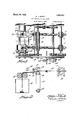
- Fig. 1 is a top View of the draft rolls and their operating mechanism and my improved feeler and stop motion applied to the machine.
- Fig. 2 is a side elevation partly in section showing the draft rolls, the guides and my feeler mechanism as applied to the machine adjacent the front draft rolls.
- Fig. 3 is an enlarged view showing two 4 pairs of feeler arms as suspended from a frame, each pair engaging its sliver ribbon one pair being separated by the sliver at its normal width and the other pair in engagement with the contact pin to close the 45 circuit and stop the machine being permitted to make this contact by the reduction in the width of the sliver.
- Fig. 4 is a perspective View of this mechanism
- Fig. 5 is a sectional elevation illustrating the contact pin on the cross-bar as being insulated from the bar and connected in the electric circuit.
- Fig. 6 is a diagrammatic view illustrating 5 the wiring diagram wherein the feeler memhers are connected in the electric circuit to 1927. semi No. 208,859.
- An apron 13 is shown as travelling over the lower front draft roll and a lower roll 14:. Adjacent to and forward of the front draft rolls 12, I have positioned a cross bar 15 under which the sliver 16 is guided on its way through the press rolls 17 to the roving cam 18.
- These arms are arranged to engage the sliver 16 as it passes under the bar 15 and rests against its opposite edges by which means these arms are naturally separated and out of circuit closing position and held in that position so long as the width of the sliver remains normal.
- each of the feeler arms 23 I have threaded a cont-act screw 28 locked in position by the lock nuts 29 so that theirlength may be regulated according to the width of the sliver to be operated upon.
- the stop motion electric circuit is closed by the feelers which are normally held out of operating position by contact with the travelling sliver when of its normal size but when this size is reduced it permits these feelers to move and complete the circuit and stop the machine and so prevent waste of the yarn by reason of the broken ends being wound about the rolls and apron by stopping the machine automatically as soon as the threads are broken.
- My improved stop motion is very simple and practical in construction, is inexpensive to manufacture and is effective in its opclaims.
- an electric circuit In a stop motion for Gill boxes, an electric circuit, a set of draft rolls to act on the sliver, a cross bar under which the sliver is led, a frame on said cross bar, a pair of cooperating feeler arms in said circuit and suspended from said frame to straddle the sliver, a contact member in the circuit supported by and insulated from said bar, adjustable contacts in said arms normally held from engagement with said contact by said sliver, whereby when fibers in the sliver are broken the volume of the sliver is reduced permitting said feeler arms to swing inwardly to close the circuit and stop the machine.
Landscapes
- Engineering & Computer Science (AREA)
- Mechanical Engineering (AREA)
- Textile Engineering (AREA)
- Replacing, Conveying, And Pick-Finding For Filamentary Materials (AREA)
- Spinning Or Twisting Of Yarns (AREA)
Description
March 20, 1928. 1,663,283
W. J. SCOTT STOP MOTION FOR GILL BOXES Fil y 27. 1927 2 Sheets-Sheet 1 54,17; I N V EN TbR. I W// J ATTORNEYS.
March 20, 1928. 1,663,283
w. J. scoTT STOP MOTION FOR GILL BOXES v Filed July 27. 1927 2 Sheets-Sheet. 2
INVENTOR. ,l za" Wi//Jdkoiif h|||| BY /J g ATTORNEYS.
Patented Mar. 20, 1928.
i 1 UNITED."
1,663,283 PATENT OFFICE.
WALTER :r. scorr, or woonsooxnr, n onn'IsLAnn.
s'ror MOTION ron GILL BOXES.
Application filed iuiy 27,
This invention relates to an improved stop motion control forGill boxes and the like; and has for its object to provide in such a stop'motion an electric circuit controlled by a feeler member which. engages the travelling sliver and is held out of circuit-closing position by the sliver when in its normal size but when the size of the sliver is reduced by reason of some of its 30 fibers becoming broken the feeler is permitted to move to close the circuit to stop the machine. I
A further object of the invention is the provision of a pair of feeler arms which straddle the travelling sliver, the arms being normally held by the size or width of the sliver out of circuit-closing position, either one or both of said arms being permitted to move inwardly when the size of 2 the sliver is reduced by the breaking of fibers therein thus permitting these arms to swing inward and engage the contact member and close the circuit to operate a belt-shifting mechanism. to stop the machine.
Vith these and other objects in view, the invention consists of certain novel features of construction, as will be more fully described, and particularly pointed out in the appended claims.
In the accompanying drawings:
Fig. 1 is a top View of the draft rolls and their operating mechanism and my improved feeler and stop motion applied to the machine.
Fig. 2 is a side elevation partly in section showing the draft rolls, the guides and my feeler mechanism as applied to the machine adjacent the front draft rolls.
Fig. 3 is an enlarged view showing two 4 pairs of feeler arms as suspended from a frame, each pair engaging its sliver ribbon one pair being separated by the sliver at its normal width and the other pair in engagement with the contact pin to close the 45 circuit and stop the machine being permitted to make this contact by the reduction in the width of the sliver.
Fig. 4; is a perspective View of this mechanism Fig. 5 is a sectional elevation illustrating the contact pin on the cross-bar as being insulated from the bar and connected in the electric circuit.
Fig. 6 is a diagrammatic view illustrating 5 the wiring diagram wherein the feeler memhers are connected in the electric circuit to 1927. semi No. 208,859.
complete this circuit when swung inward to engagethe contact pin and so operate the belt-shifting mechanism to stop the n'iachine.
Itis found in the practical operation of Gill boxes and other machines of this character where the sliver is passed through the machine in ribbon form that often the fibers of the sliver are broken by action of the draft rolls and the broken ends are wound upon the rolls or upon the apron, thereby reducing the volume or size of the sliver. In order to stop the machine when the fibers of the sliver are so broken, I havemounted a pair of feeler arms in position to straddle the different sliver ribbons as they are travelling through the machine, the feelers of each pair lying against the opposite side edges of its sliver ribbon so that when the volume, size or width of the sliver is reduced by reason'of the fibers becoming broken and wound upon'the draft rolls or apron these feelers will follow the reduced sliverand swing inwardly and engage a contact member to complete the electric circuit and operate a stop motion to stopthe machine thus calling attention of the attendant to the trouble and when this trouble is remedied and the fibers of the sliver are repositioned and the sliver restored to its normal size the machine.may again be set in operation; and theffollowing'is a detailed description of the present embodiment of my invention and showing one means by which these advantageous results may be accomplished With reference to the drawings, 10 designates the frame of the machine in which are mounted the rear draft rolls 11 and the front draft rolls 12. An apron 13 is shown as travelling over the lower front draft roll and a lower roll 14:. Adjacent to and forward of the front draft rolls 12, I have positioned a cross bar 15 under which the sliver 16 is guided on its way through the press rolls 17 to the roving cam 18.
On this cross bar, I have mounted a frame 19 comprising uprights 20 and horizontal bar 21. On this horizontal bar, I have sus pended from the pivots 22 the two feeler arms 23 of each pair to swing freely thereon,
the lower ends of these arms being weighted as at 24 causing them to normally swing to a vertical position.
These arms are arranged to engage the sliver 16 as it passes under the bar 15 and rests against its opposite edges by which means these arms are naturally separated and out of circuit closing position and held in that position so long as the width of the sliver remains normal.
In the cross bar 15, I have set a contact pin 25 which is insulated as at 26 from this cross bar and is connected by wire 27 in the electric circuit. 2
In each of the feeler arms 23, I have threaded a cont-act screw 28 locked in position by the lock nuts 29 so that theirlength may be regulated according to the width of the sliver to be operated upon. In order to stop the machine electrically when these feeler arms 23 are permitted to swing inward and close the circuit, I have provided a beltshift rod 30 held by latch mechanism 31 against action of the detent spring 32 whereby when the circuit becomes energized the electromagnets 33 withdraw the detent rod 34 from engagement with the latch 31 and permit spring 32 to move the rod 3O, and so shift the belt from the drive pulley 85 to the loose pulley 36 thus arresting the action of the machine.
By my improved stop motion for the Grill boxes or other similar textile machines, it will be seen that the stop motion electric circuit is closed by the feelers which are normally held out of operating position by contact with the travelling sliver when of its normal size but when this size is reduced it permits these feelers to move and complete the circuit and stop the machine and so prevent waste of the yarn by reason of the broken ends being wound about the rolls and apron by stopping the machine automatically as soon as the threads are broken.
My improved stop motion is very simple and practical in construction, is inexpensive to manufacture and is effective in its opclaims.
I claim:
1. In a stop motion for Gill boxes, an electric circuit, a set of draft rolls to act on the sliver, a pair of pivotally suspended feeler arms arranged to straddle the travelling sliver and held from circuit-closing position by contact with opposite edges of the travelling sliver whereby when fibers from the sliver are broken by action of the rolls the width of the sliver is reduced permitting one of said feelers to move and close the circuit to stop the machine.
2. In a stop motion for Gill boxes, an electric circuit, a set of draft rolls to act on the sliver, a cross bar under which the sliver is led, a frame on said cross bar, a pair of cooperating feeler arms in said circuit and suspended from said frame to straddle the sliver, a contact member in the circuit supported by and insulated from said bar, adjustable contacts in said arms normally held from engagement with said contact by said sliver, whereby when fibers in the sliver are broken the volume of the sliver is reduced permitting said feeler arms to swing inwardly to close the circuit and stop the machine.
In testimony whereof I aflix my signature.
WALTER J. SCOTT.
Priority Applications (2)
| Application Number | Priority Date | Filing Date | Title |
|---|---|---|---|
| US208859A US1663283A (en) | 1927-07-27 | 1927-07-27 | Stop motion for gill boxes |
| GB13329/28A GB294601A (en) | 1927-07-27 | 1928-05-05 | Improvements in stop motion for gill boxes |
Applications Claiming Priority (1)
| Application Number | Priority Date | Filing Date | Title |
|---|---|---|---|
| US208859A US1663283A (en) | 1927-07-27 | 1927-07-27 | Stop motion for gill boxes |
Publications (1)
| Publication Number | Publication Date |
|---|---|
| US1663283A true US1663283A (en) | 1928-03-20 |
Family
ID=22776320
Family Applications (1)
| Application Number | Title | Priority Date | Filing Date |
|---|---|---|---|
| US208859A Expired - Lifetime US1663283A (en) | 1927-07-27 | 1927-07-27 | Stop motion for gill boxes |
Country Status (2)
| Country | Link |
|---|---|
| US (1) | US1663283A (en) |
| GB (1) | GB294601A (en) |
Cited By (1)
| Publication number | Priority date | Publication date | Assignee | Title |
|---|---|---|---|---|
| US2679073A (en) * | 1952-06-28 | 1954-05-25 | Walter J Scott | Stop motion device for yarn processing machines |
-
1927
- 1927-07-27 US US208859A patent/US1663283A/en not_active Expired - Lifetime
-
1928
- 1928-05-05 GB GB13329/28A patent/GB294601A/en not_active Expired
Cited By (1)
| Publication number | Priority date | Publication date | Assignee | Title |
|---|---|---|---|---|
| US2679073A (en) * | 1952-06-28 | 1954-05-25 | Walter J Scott | Stop motion device for yarn processing machines |
Also Published As
| Publication number | Publication date |
|---|---|
| GB294601A (en) | 1929-01-03 |
Similar Documents
| Publication | Publication Date | Title |
|---|---|---|
| US1870095A (en) | Reducing device for slivers for drawing mechanisms for textile slivers | |
| US3304584A (en) | Drafting mechanism | |
| US1663283A (en) | Stop motion for gill boxes | |
| US3873043A (en) | Yarn guide- and monitoring apparatus for a bobbin creel | |
| US3271823A (en) | Stop motion for textile fiber drafting machine | |
| US3305896A (en) | Creel stop motion | |
| US2079122A (en) | Drafting mechanism | |
| US3021401A (en) | Thread or yarn breakage detector | |
| GB1156457A (en) | Improvements in Stop Motions for Textile Twisting Frames | |
| US2023515A (en) | Thread feeding mechanism | |
| US2007643A (en) | Stop motion for fiber strand preparation machines | |
| US1403454A (en) | Tension device for spoolers | |
| US2679073A (en) | Stop motion device for yarn processing machines | |
| US3363285A (en) | Drawing frame stop motion | |
| US1900400A (en) | Stop motion for gill boxes | |
| US3330007A (en) | Lapper stop motion | |
| US2763035A (en) | Stop mechanism | |
| US2086096A (en) | Stop motion for textile apparatus | |
| US1791289A (en) | Stop motion | |
| US2064869A (en) | Stop motion | |
| US2167907A (en) | Warp stop motion | |
| US2399148A (en) | Stop motion for drawing frames | |
| US3947923A (en) | Fiber condenser | |
| US2312558A (en) | Knock-off mechanism for drawing frames | |
| US2270032A (en) | Warp beaming machine |