US1663248A - Worktable - Google Patents
Worktable Download PDFInfo
- Publication number
- US1663248A US1663248A US77685A US7768525A US1663248A US 1663248 A US1663248 A US 1663248A US 77685 A US77685 A US 77685A US 7768525 A US7768525 A US 7768525A US 1663248 A US1663248 A US 1663248A
- Authority
- US
- United States
- Prior art keywords
- secured
- edge
- track
- bars
- straight edge
- Prior art date
- Legal status (The legal status is an assumption and is not a legal conclusion. Google has not performed a legal analysis and makes no representation as to the accuracy of the status listed.)
- Expired - Lifetime
Links
Images
Classifications
-
- B—PERFORMING OPERATIONS; TRANSPORTING
- B25—HAND TOOLS; PORTABLE POWER-DRIVEN TOOLS; MANIPULATORS
- B25H—WORKSHOP EQUIPMENT, e.g. FOR MARKING-OUT WORK; STORAGE MEANS FOR WORKSHOPS
- B25H1/00—Work benches; Portable stands or supports for positioning portable tools or work to be operated on thereby
Definitions
- This invention relates to work" tables and more particularly to a combined lay-out and cutting table for use in upholstering and other shops in which cloth and. other flexible material is worked upon in quantity.
- the present invention provides means whereby suitable lay-out bars may be ad just-ed over the material on thetable and,
- the present table provides for a plurality of adjustable cutters which may be set at any desired point across the width of the table and said cutters will automatically and continuously cut the material so it is wound on the receiving roll.
- Another object of the invention is to provide means adjustable transversely of the table for automatically forming continuous marks lengthwise of the material during the movement of the material along the table.
- a further object is to provide a table with adjustable lay-out mechanism for working on various widths of material.
- a still further object is to provide a'table having the novel design, construction and combination of parts hereinafterdescribed and illustrated in the accompanying. drawings.
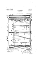
- Figure 1 is a plan view of a table embodying this invention. 1
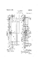
- Figure 2 is a side elevation thereof.
- Figure 3 is a sectional elevation on the line III-III of Figure 1.
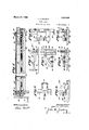
- Figure 4 is a transverse sectional elevation on theline IVIV of Figure 3.
- Figures 5 and 6 are a detail plan and side elevation showing the cutting tool holders and cutters.
- Figure 7 is a detail pencil marking tools.
- Figures 8 and 9 area. elevation of a marking tool.
- Figures 10 and 11 are a detail plan and sidp elevation of another form of marking too r
- the letter A designates the table as a whole which comprises a top 2 and legs 3, which legs are secured together by tie strips 4.
- a second pair of brackets 10 are secured to the table legs 3 at the forward end of the table and are provided with slots 11 in their upper facesto provide bearingsfor the material receiving roll 12 which is provided with a hand operating crank 12 and a pulley 12 which is for power operation if desired.
- An anti-friction roller 14.- is journaled in suitable brackets 15 secured to the forward end edge of the table top' 2.
- a straight edge 17 extendssubstantially theentire length of the table in close, proximityiwiththe side edge ofthe, table.- Thestraight edge 17 is bolted or otherwise rigidly secured in place- A second straight edge '18 is slidably mounted on top of the table intermediate the sides thereof.
- the toprface of the table is slotted transversely at 19 to provide a" path for a guide block 20 secured.
- the block 20 is provided with a-nut 24 which is threaded on a screw shaft'25 journaled at 26'and 27 and'provided with a hand wheel 28 for operating the same.
- Suitable filler blocks 29 are removably mounted in the slot 19 in the table top 2 so as to provide a continuous working top, said blocks being adapted to be removed when the straight edge 18 is adjusted.
- lay-out bars 30, 31, 32, 33, and 34 are provided. These lay-out bars are provided U-shaped clamping ends 35 adapted to fit over the straight edges and are adapted to extend transversely of the table at various angles. The clamping ends 35 of the bars are each provided with a set screw 36 adapted to lock the bars in adjusted position. V
- a track member 37 extends transversely of and is secured to the table adjacent the forward or receiving roll end and is elevated above the table top 2 so as to permit the material being worked upon which is designated by the letter B to pass thereunder.
- a plurality of tool holders 38, 39, 40 and 4% are adapted to be mounted on the track 3 knives 44'removably secured therein and'to be adjusted to various positions on the.
- the tool holder 39 is composed of a track engaging portion 46 and a spring or resilient tongue portion 47-having a tool receiving aperture adapted to contain a pencil or other marker 48 which engages and marks the :material B as it passes thereunder.
- the tool body portion 49 which is grooved at 50 to 'fit over the track 37 and is provided with anti-friction rollers 51 in the groove 50.
- a shaft 52 is removably journaled in the body portion 49 and is held in position by a'set screw 53.
- a plurality of marker rollers or disks 54 are mounted on the shaft 52 and held in spaced relation by sleeve members 55. The spacing of the disks 54 may be varied by substituting sleeves 55 of varying lengths. 4
- the tool holder 42 comprises a pair of spaced track engaging members 56 provided with set screws 57 for locking thelm in place on the track, uponwhich they area'djustably mounted.
- Each of the members 56 is provided with a bearing 58 to receive a shaft 59 whichcarries marking disks 60 held in
- the tool holders 38 are shown in detail in' Figures 5 and 6 and are adapted to have sleeves 61 of varying lengths. I
- a roll of material 13 is first mounted on the feed roller 7 and the material is drawn along the table, inserted under the track 37 and secured by tacking, or otherwise, to the receiving roller 12.
- he strai ht edge 18 is then adjusted to the width of the material and the several lay-out bars are positioned as desired for laying out the work piece and locked in position by the set screws 36. If any of the tool holders 38, 39, or 41 are desired they are also adjusted along the track 37 and locked in position.
- a pencil or other marker may then be run along the lay-out bars to mark the material B and after their positions have been marked the receiving roll 12 will'be rotated to take up the marked material and bring,
- the tool holder 40' is to be used to mark transverse lines on the material the other toolholders are removed irom the track 37 and the holder 40 is moved manually alongthe track 37 when desired to mark adapted to facilitate the setting up of the.
- a work table for laying outand otherwise working on cloth and other flexible material comprising an elongated table portion, a fixed straight'edge adjacent oneside edge of saidtable, a second straight edge adjustably mounted between theside'edges of said table, screw means for adjusting said adjustable straight edge transversely of said table and a plurality of layout bars-adjustably mounted on said straight edges: and extending transversely of said table, atleast some of said layout bars beingconnected to both said stationary. and said adjustable straight edges, and said last named layout bars being extensible.
- a work table for laying out and otherwise working on cloth and other flexible material comprising an elongated table portion, a fixed'straight edge adjacent one side edge of said table, a second straight edge adjustably mounted between the side edges of said table, said table being provided with a transversely extending guide slot intermediate its ends, a guide block secured to the lower face of said adjustable straight edge and extending into said slot, a nut in said block, bearings secured adjacent each side edge of said table, a screw shaft journaled in said bearings and having athreaded engagement with said nut, and means for rotating said shaft to cause a transverse movement of said adjustable straight edge relative to said table.
- a work table for laying out and otherwise working on cloth and other flexible material comprising an elongated table portion, a fixed straight edge adjacent one side edge of said table, a second straight edge adjustably mounted between the side edges of said table, screw means for adjusting said adjustable straight edge transversely of said table and a plurality of layout bars adjustably and removably mounted on said straight edges, at least one of said layout bars being extensible and being provided with a pivot joint adjacent each end so as to permit said bar to be arranged transversely between saidstraight edges at an angle to the transverse axis of said table.
- a work table for laying out and otherwise working on cloth and other flexible material comprising an elongated table portion, a fixed straight edge adjacent one side edge of said table, said table having a transversely extending slot intermediate the ends of its top, grooved guide strips secured to the bottom face of the table top and parallel ing the sides of said slot, a second-straight edge adjustably mounted between the side edges of said table, a guide block secured to the lower face of said adjustable straight edge and extending into said slot, flanges on said guide block and extending into the grooves in said guide strips, a nut in said block, bearings secured tov said table adjal cent each of its side edges, a screw shaft journaledin said bearings and havinga threaded engagement with said nut, and means for rotating said shaft to cause a transverse movement of said adjust-able straight edge relative to said table.
- a work table for laying out and otherwise Working on cloth and other flexible material comprising in combination, an elon- ,7
- the material to be operated upon being adapted to be first drawn across said table by hand from said feed roll and secured to said receiving roll, means for rotating.
- said receiving roll to move said material across said table, an inverted T-shaped track member fixedly mounted on and extending transversely of said table adjacent the receiving roll end, said track member being elevated above said table to permit the material bein worked 11 3011 to ass thereunder and a plurality of tool holders mounted on said track and adapted to contain tools for marking and cutting the material being worked upon, at least some of said tool holders being adapted to be removably locked in position on said track.
Landscapes
- Engineering & Computer Science (AREA)
- Mechanical Engineering (AREA)
- Treatment Of Fiber Materials (AREA)
Description
- 1,663,248 J. A. FRITSCH C WORK TABLE Filed Dec. 26, 1925 s Sheets-Sheet 1 March 20, 1928. 1,663,248
J. A. FRITSCH WORK TABLE Filed Dec. 26, 1925 s Sheets-Sheet 2 wn Jay/W- 4. 2 75 ,H v 8 3 A 4 f t J 3 sww w 4 fir e m m 3 1 N K K H 04 C E l S L w H m m z R T F M W A W H m m & 2 s W m w i 0 25.: 5 REE:=25:=sEg 255522552-E m s 2 i. l m U e a r L 1. M y
Patented Mar. 2Q, 1928.
. TATE JOHN A. rnrrson, or PITTSBURGH, PENNSYLVANIA.
. wonxranrin.
Application filed December 26, 1925. Serial No. 77,685.
This invention relates to work" tables and more particularly to a combined lay-out and cutting table for use in upholstering and other shops in which cloth and. other flexible material is worked upon in quantity.
In upholstering shops for instance it is often necessary to lay-out a considerable number oil-articles of duplicate design and considerable time is consumed by expert workmen in laying out or marking these articles. I p
The present invention provides means whereby suitable lay-out bars may be ad just-ed over the material on thetable and,
locked inposition and when the one article is laid out the material will be rolled up on a receiving roll thereby moving a new length of material under the lay-out bars. After the second article is laid out the receiving roll is again rotated to take'up that length of material, and the operation may thus be continued until all the articles desired are laid out. A further advantage of this table is that after the lay-out bars are once set in the desired position any unskilled labor may be used to mark .the material. i
It is also aften necessary to out long narrow strips of material from wide material and this also necessitates considerable labor. while the present table provides for a plurality of adjustable cutters which may be set at any desired point across the width of the table and said cutters will automatically and continuously cut the material so it is wound on the receiving roll. a
' Another object of the invention is to provide means adjustable transversely of the table for automatically forming continuous marks lengthwise of the material during the movement of the material along the table.
A further object is to provide a table with adjustable lay-out mechanism for working on various widths of material.
A still further object is to provide a'table having the novel design, construction and combination of parts hereinafterdescribed and illustrated in the accompanying. drawings.
In the drawings: Figure 1 is a plan view of a table embodying this invention. 1
Figure 2 is a side elevation thereof.
Figure 3 'is a sectional elevation on the line III-III of Figure 1.
Figure 4 is a transverse sectional elevation on theline IVIV of Figure 3.
Figures 5 and 6 are a detail plan and side elevation showing the cutting tool holders and cutters.
Figure 7 is a detail pencil marking tools.
Figures 8 and 9 area. elevation of a marking tool.
Figures 10 and 11 are a detail plan and sidp elevation of another form of marking too r Referring moreparticularly, to the drawings the letter A designates the table as a whole which comprises a top 2 and legs 3, which legs are secured together by tie strips 4.
'Brackets 5 having bearingslots .6 are secured to the tablelegs 3 at the rear end and form a support fora material, supply and feed roller 7which is removably journaled insaidslotsfi i An antifriction roller 8 is journaled in. suitable brackets 9 secured to the rear end edge of the table top'12.
A second pair of brackets 10 are secured to the table legs 3 at the forward end of the table and are provided with slots 11 in their upper facesto provide bearingsfor the material receiving roll 12 which is provided with a hand operating crank 12 and a pulley 12 which is for power operation if desired. v u
An anti-friction roller 14.- is journaled in suitable brackets 15 secured to the forward end edge of the table top' 2. v v
A straight edge 17 extendssubstantially theentire length of the table in close, proximityiwiththe side edge ofthe, table.- Thestraight edge 17 is bolted or otherwise rigidly secured in place- A second straight edge '18 is slidably mounted on top of the table intermediate the sides thereof. The toprface of the table is slotted transversely at 19 to provide a" path for a guide block 20 secured. to the lower side elevation of one of the of the straight'edge 18, which block is provided with flanges 21 adapted to'fit in guideways 22 formed in guide strips 23 secured to the bottom sideor the tabletop 2.. The block 20 is provided with a-nut 24 which is threaded on a screw shaft'25 journaled at 26'and 27 and'provided with a hand wheel 28 for operating the same.
If desired ofv course suitable speed up gearing maybein-v terposed between the hand wheel and shaft.
detail plan and side It will be seen from the above that the straight edge 18 may be readily moved transversely of the table by revolving the shaft by its hand wheel 28.
Suitable filler blocks 29 are removably mounted in the slot 19 in the table top 2 so as to provide a continuous working top, said blocks being adapted to be removed when the straight edge 18 is adjusted.
A variety of lay-out bars 30, 31, 32, 33, and 34 are provided. These lay-out bars are provided U-shaped clamping ends 35 adapted to fit over the straight edges and are adapted to extend transversely of the table at various angles. The clamping ends 35 of the bars are each provided with a set screw 36 adapted to lock the bars in adjusted position. V
A track member 37 extends transversely of and is secured to the table adjacent the forward or receiving roll end and is elevated above the table top 2 so as to permit the material being worked upon which is designated by the letter B to pass thereunder. A plurality of tool holders 38, 39, 40 and 4% are adapted to be mounted on the track 3 knives 44'removably secured therein and'to be adjusted to various positions on the.
track and locked in position by set screws 45.
The tool holder 39, of which there may be any number, is composed of a track engaging portion 46 and a spring or resilient tongue portion 47-having a tool receiving aperture adapted to contain a pencil or other marker 48 which engages and marks the :material B as it passes thereunder. The tool body portion 49, which is grooved at 50 to 'fit over the track 37 and is provided with anti-friction rollers 51 in the groove 50. A shaft 52 is removably journaled in the body portion 49 and is held in position by a'set screw 53. A plurality of marker rollers or disks 54 are mounted on the shaft 52 and held in spaced relation by sleeve members 55. The spacing of the disks 54 may be varied by substituting sleeves 55 of varying lengths. 4
The tool holder 42 comprises a pair of spaced track engaging members 56 provided with set screws 57 for locking thelm in place on the track, uponwhich they area'djustably mounted. Each of the members 56is provided with a bearing 58 to receive a shaft 59 whichcarries marking disks 60 held in The tool holders 38 are shown in detail in' Figures 5 and 6 and are adapted to have sleeves 61 of varying lengths. I
In operation a roll of material 13 is first mounted on the feed roller 7 and the material is drawn along the table, inserted under the track 37 and secured by tacking, or otherwise, to the receiving roller 12.
he strai ht edge 18 is then adjusted to the width of the material and the several lay-out bars are positioned as desired for laying out the work piece and locked in position by the set screws 36. If any of the tool holders 38, 39, or 41 are desired they are also adjusted along the track 37 and locked in position.
A pencil or other marker may then be run along the lay-out bars to mark the material B and after their positions have been marked the receiving roll 12 will'be rotated to take up the marked material and bring,
an unmarked section of material onto the table top 2 in position for marking. As the material is being wound .up on the receiving roll 12 the tools of the tool holders 38, 39, and 41 will automatically mark or cut the material.
It the tool holder 40' is to be used to mark transverse lines on the material the other toolholders are removed irom the track 37 and the holder 40 is moved manually alongthe track 37 when desired to mark adapted to facilitate the setting up of the.
various lay-out bars and tools.
While I have shown and described one specific embodiment of my inventionit will be understood that I do notwish to be limited thereto since various modificationsmay be made without departing from the scope of my invention as defined in the appended claims.
What I claim is:
1. A work table for laying outand otherwise working on cloth and other flexible material, comprising an elongated table portion, a fixed straight'edge adjacent oneside edge of saidtable, a second straight edge adjustably mounted between theside'edges of said table, screw means for adjusting said adjustable straight edge transversely of said table and a plurality of layout bars-adjustably mounted on said straight edges: and extending transversely of said table, atleast some of said layout bars beingconnected to both said stationary. and said adjustable straight edges, and said last named layout bars being extensible.
2. A work table for laying out and otherwise working on cloth and other flexible material, comprising an elongated table portion, a fixed'straight edge adjacent one side edge of said table, a second straight edge adjustably mounted between the side edges of said table, said table being provided with a transversely extending guide slot intermediate its ends, a guide block secured to the lower face of said adjustable straight edge and extending into said slot, a nut in said block, bearings secured adjacent each side edge of said table, a screw shaft journaled in said bearings and having athreaded engagement with said nut, and means for rotating said shaft to cause a transverse movement of said adjustable straight edge relative to said table. I
3. A work table for laying out and otherwise working on cloth and other flexible material, comprising an elongated table portion, a fixed straight edge adjacent one side edge of said table, a second straight edge adjustably mounted between the side edges of said table, screw means for adjusting said adjustable straight edge transversely of said table and a plurality of layout bars adjustably and removably mounted on said straight edges, at least one of said layout bars being extensible and being provided with a pivot joint adjacent each end so as to permit said bar to be arranged transversely between saidstraight edges at an angle to the transverse axis of said table.
4. A work table for laying out and otherwise working on cloth and other flexible material, comprising an elongated table portion, a fixed straight edge adjacent one side edge of said table, said table having a transversely extending slot intermediate the ends of its top, grooved guide strips secured to the bottom face of the table top and parallel ing the sides of said slot, a second-straight edge adjustably mounted between the side edges of said table, a guide block secured to the lower face of said adjustable straight edge and extending into said slot, flanges on said guide block and extending into the grooves in said guide strips, a nut in said block, bearings secured tov said table adjal cent each of its side edges, a screw shaft journaledin said bearings and havinga threaded engagement with said nut, and means for rotating said shaft to cause a transverse movement of said adjust-able straight edge relative to said table.
5. A work table for laying out and otherwise Working on cloth and other flexible material, comprising in combination, an elon- ,7
gated rigid table portion, a material supporting and feed roll at one end and below the upper edge of said table, a material receiving roll 'at the other end and below the upper edge of said table, anti-friction rollers along each or" the end edges of saidtable,
the material to be operated uponbeing adapted to be first drawn across said table by hand from said feed roll and secured to said receiving roll, means for rotating.
said receiving roll to move said material across said table, an inverted T-shaped track member fixedly mounted on and extending transversely of said table adjacent the receiving roll end, said track member being elevated above said table to permit the material bein worked 11 3011 to ass thereunder and a plurality of tool holders mounted on said track and adapted to contain tools for marking and cutting the material being worked upon, at least some of said tool holders being adapted to be removably locked in position on said track. I
In testimony whereof I aflix my signature.
JOHN A. FBITSOH.
Priority Applications (1)
| Application Number | Priority Date | Filing Date | Title |
|---|---|---|---|
| US77685A US1663248A (en) | 1925-12-26 | 1925-12-26 | Worktable |
Applications Claiming Priority (1)
| Application Number | Priority Date | Filing Date | Title |
|---|---|---|---|
| US77685A US1663248A (en) | 1925-12-26 | 1925-12-26 | Worktable |
Publications (1)
| Publication Number | Publication Date |
|---|---|
| US1663248A true US1663248A (en) | 1928-03-20 |
Family
ID=22139491
Family Applications (1)
| Application Number | Title | Priority Date | Filing Date |
|---|---|---|---|
| US77685A Expired - Lifetime US1663248A (en) | 1925-12-26 | 1925-12-26 | Worktable |
Country Status (1)
| Country | Link |
|---|---|
| US (1) | US1663248A (en) |
Cited By (1)
| Publication number | Priority date | Publication date | Assignee | Title |
|---|---|---|---|---|
| US2559982A (en) * | 1946-12-13 | 1951-07-10 | Pittsburgh Plate Glass Co | Attachment for cutting tables |
-
1925
- 1925-12-26 US US77685A patent/US1663248A/en not_active Expired - Lifetime
Cited By (1)
| Publication number | Priority date | Publication date | Assignee | Title |
|---|---|---|---|---|
| US2559982A (en) * | 1946-12-13 | 1951-07-10 | Pittsburgh Plate Glass Co | Attachment for cutting tables |
Similar Documents
| Publication | Publication Date | Title |
|---|---|---|
| DE2538737A1 (en) | TOOL GRINDING MACHINE | |
| US1958203A (en) | Routing machine | |
| US1663248A (en) | Worktable | |
| US3506254A (en) | Fabric laying machine with selective engagement of cutting means or spreading means | |
| US451006A (en) | Apparatus for marking and cutting cloth | |
| US394594A (en) | Stereotype-finishing machine | |
| US1078302A (en) | Cloth-laying machine. | |
| US611599A (en) | Metal cutter and roller | |
| US1135714A (en) | Block-refinisher. | |
| US995454A (en) | Device for carving and gaining. | |
| US717454A (en) | Woodworking-machine. | |
| US766158A (en) | Machine for cutting curves. | |
| US610526A (en) | Card-cutting machine | |
| US722093A (en) | Machine for trimming wall-paper. | |
| US1208527A (en) | Machine for making saw-toothed metal fasteners. | |
| US96301A (en) | Improvement in machine for shaping wooden trays | |
| US435610A (en) | Cloth-cutting apparatus | |
| US676228A (en) | Bias-cutting table. | |
| US521224A (en) | Box-machine | |
| US1929893A (en) | Scoring machine | |
| US160016A (en) | Improvement in paper-perforating machines | |
| US122674A (en) | Improvement in machines for chamfering the rails of wagon-bodies | |
| US2790472A (en) | Machine for making tapered dove-tails | |
| US960408A (en) | Abrading-machine. | |
| US5575A (en) | Alfred t |