US1663239A - Frederick a - Google Patents
Frederick a Download PDFInfo
- Publication number
- US1663239A US1663239A US1663239DA US1663239A US 1663239 A US1663239 A US 1663239A US 1663239D A US1663239D A US 1663239DA US 1663239 A US1663239 A US 1663239A
- Authority
- US
- United States
- Prior art keywords
- disk
- zone
- metal
- spool
- disks
- Prior art date
- Legal status (The legal status is an assumption and is not a legal conclusion. Google has not performed a legal analysis and makes no representation as to the accuracy of the status listed.)
- Expired - Lifetime
Links
Images
Classifications
-
- A—HUMAN NECESSITIES
- A01—AGRICULTURE; FORESTRY; ANIMAL HUSBANDRY; HUNTING; TRAPPING; FISHING
- A01B—SOIL WORKING IN AGRICULTURE OR FORESTRY; PARTS, DETAILS, OR ACCESSORIES OF AGRICULTURAL MACHINES OR IMPLEMENTS, IN GENERAL
- A01B23/00—Elements, tools, or details of harrows
- A01B23/06—Discs; Scrapers for cleaning discs; Sharpening attachments
Definitions
- My invention relates to improvements in the construction of earth working disks such as used on tillage machines and the objects of the invention are to provide a form of disk that will sustain the strain to which they are subjected in action without breaking and that will permit assembly of several disks in a gang in a simple and economical manner, thus improving the efliciency of such implements as disk harrows, cultivators, etc.
- Fig. 1 is a plan or face view of a disk constructed according to my invention.
- Fi re 2 is a diametrical section through the 'sk.
- Figure 3 is a view of the disks as assem- Serial No. 585,364.
- the disk of my invention is formed from plate steel of uniform thickness and of any gage ordinarily employed in disk manufacturing.
- the main body 10 of the disk does not differ in shape from that of ordinary disks, but the central portion is formed with a pressed out or offset hub portion 11 formed by forcing metal of the disk outwardly at the back, thus forming a saucer-shaped depression in the face of the disk.
- This depression has a plane or flat floor corresponding in area to that of the spool heads between which the disks are to be clamped and has a diameter approximately one-fourth that of the disk.
- This flat portion is perforated at its center, which is the axis of the disk, as at 12, for the reception of a supporting shaft 13.
- This perforation may be either polygonal or round according as the disks are to turn with the shaft or on it.
- the metal is crimped or corrugated to describe a gradual reverse or ogee curve, as at 14 (Fig. 2), thus presenting on the face of the disk a rounded shoulder 15 having a comparatively long radius of curvature, and on the back of the disk a second rounded shoulder 16 having a shorter radius of curvature.
- the supportin elements or flanges in engagement with t e disk will extend to the margin of the flat portion and preferably will enga e its entire area and reach to the edge 0 the zone occupied by the curved portion 14.v
- the metal forming the sides of the depression 11 be given the proper curve and that the reverse curvature of the portions or shoulders 15, 16 shall be neither too abrupt nor too flat.
- the metal of the disk in the zone immediately surrounding the spool heads of the assembled disk gang shall have a certain degree of resiliency in order that the highest resistance to center breakage of the disk may be obtained. I have discovered that the correct degree of resiliency to secure this result in a 16 inch.
- disk of standard curvature is produced by such a reversely curved or substantially corrugated circular portion as that shown in the drawings. This corrugated portion may be considered as having the face shoulder 15 and the back shoulder 16.
- the curve of the shoulder 15 should be on a radius of close to 1 inches and that of the shoulder 16 on a radius of approximately of an inch, while the flat center to 'be occupied by the clamping elements should be about four inches in diameter.
- the zone of deformation within which. these curves lie is, therefore, narrow, the total diameterof the pressed out portion on the convex side of the disk being only approxi mately one-third the diameter of the entire disk which, therefore, retains the shape and soil turning characteristics of the ordinary earth working disk throughout its effective area.
- Disks constructed according to my invention are mounted in gangs in the usual manner on a shaft or axle 13 between spacing spools 17. the spools and disks being drawn up and tightly clamped. but, owing to the fact that the bottom of the hub por-- tion or cepression 11 on the disks is preferably flat, the spool ends or heads are also made flat and the necessity for grinding the spool ends to fit a concave-convex disk, as has heretofore been done, is eliminated, thereby further lessening the cost of manufacture and giving an improved gang construction.
- the working thrusts acting on the face of the disk near its periphery are not concentrated in the metal immediately surrounding the edges of the spool ends, thereby causing crystallization at this point and parting of the metal, as has here tofore happened, the bent portion adjacent the edge of the spool head in my improved construction acting to change the direction of thrust and diffuse the strain throughout a greater area of the metal in the disk immediately surrounding the hub'thus greatly increasing its endurance and making it pos sible for the disk to withstand working strains indefinitely.
- an earth Working disk with the greater part of its radial extent of ordinary concave-convex form and having asmaller central. hub p013 tion, corresponding in shape and size to conventional supporting spool heads, pressed out and forming a protrusion on its convex side, said central hub portion being delimited by a narrow zone Within which the metal of the disk is crimped.
- an earth working disk having a main or body portion of ordinary concavo convex -form and formed'with ahub portion pressed out to form a protrusion on its convex side delimited by a zone within which the metal of the disk is crimped, the diameter of said hub portion and crimped zone together being approximately one-third the diameter of the disk.
- a disk for earth working implements having a main or body portion of ordinary concave-convex form and provided with a lnihportion delimited by a zone in which the metal of the disk is bent on a reverse curve, said hub forming a protrusion on the convex side of the disk.
- the width of the area within said zone being approximately one fourth that of the disk and corresponding to that of disk supporting heads of; standard type.
- a disk for earth working implements having a, main portion or body of ordinary concavoconvex form and provided with a hub portion ofthcsame thickness as the disk and consisting of a flattened area delimited by a zone in which the metal of the disk is bent on a reverse curve, saidhub portion forming a protrusion on the convex side of the disk, the width of said, flattened area being approximately one fourth that of the, disk andcorresponding to thatof disk supporting heads of standardtype.
- a disk implement comprising an ordiT nary concavo-convex disk having an integral
- fiat hub portion approximately one. fourth the width of thedisk pressed out atlthe back of the disk, themetalsurrounding said flat. portlon merging with the body of the disk.
- an ordinary con cave-convex disk having. an integral flat hub, portion otfsetrearwardly from the convex side of the disk with themetal'aroundthe" margin of saidfiatportio'n reversely curved i to provide a resilient zonesurrounding it, said fiat portion being approximately [one fourth the widthof the disk, and supporting means for the diskcomprising spools engag-f ing the opposite surfaces-of said flat portion.
- a concavo-convex earth working disk having a central hub portion pressed out to form a protrusion on its convex side delimited by a narrow zone within which the metal of the disk is crimped, a shaft engaging said hub portion, and a supporting spool on the shaft in clamping engagement with a face of said protruding hub portion, said spool having a head the periphery of which lies at the inner margin of said crimped zone.
- a disk implement the combination of an earth working disk having its greater part of ordinary concavo-convex form and a relatively small central hub portion pressed out to form a protrusion on its convex side delimited by a narrow zone within which the metal of the disk is crimped, a shaft engaging said hub portion, and a supporting spool on the shaft in clamping engagement with a. face of said protruding hub ortion, said spool having a head the perip cry of which lies at the inner margin of said crimped zone.
- a concavo-convex earth working disk having the greater part of its radial extent of standard curvature
- a supporting spool head engaging a surface of the disk in a zone surrounding the disk axis
- means for reenforcing the disk against rupture by working stresses in the circumferential zone surrounding the spool head comprising a curvilinear deformation in the metal of the disk formed within a narrow zone immediately surrounding the margin of the spool head.
Landscapes
- Life Sciences & Earth Sciences (AREA)
- Engineering & Computer Science (AREA)
- Mechanical Engineering (AREA)
- Soil Sciences (AREA)
- Environmental Sciences (AREA)
- Storage Of Web-Like Or Filamentary Materials (AREA)
Description
March 20, 1928.
F. A BUCKNAM DISK FOR TILLAGE IMPLEMENTS fla Filed Auz. 31, 1-922 Invenfar. E66Z67/L'CAZ Patented Mar. 20, 1928.
UNITED STATES PATENT OFFICE.
FREDERICK A. BUCKNAM, OF AUBURN, NEW YORK, ASSIGNOR TO INTERNATIONAL HARVESTEB COMPANY, OF CHICAGO, ILLINOIS, A CORPORATION OF NEW JERSEY.
DISK FOR TILLAGE IMPLEMENTS.
Application filed August 31, 1922.
My invention relates to improvements in the construction of earth working disks such as used on tillage machines and the objects of the invention are to provide a form of disk that will sustain the strain to which they are subjected in action without breaking and that will permit assembly of several disks in a gang in a simple and economical manner, thus improving the efliciency of such implements as disk harrows, cultivators, etc.
It is well known to those skilled in the art that the disks of tillage implements tend, after a certain period of use, to break out at the center, the lateral thrust of the soil on the outer portion of the disks acting to gradually weaken the metal at the point where the disks meet the flanges of the spacing spools between which they are held, breaka e being no doubt due to crystallization of the metal at the point of greatest strain. Heretofore this tendency could only be overcome either by increasing the thickness of each disk towards its center or by bracing or backing up the disk as by enlarging the flange on the s acing spools, either method ad ing materia ly to the cost of construction and the weight of the implement.
I have found that by shaping the center of an ordinary concavo-convex disk in a special wa while leaving the greater part of its ra ial extent unaltered and mounting it between spacing spools, the working strains will be so distributed in the metal that the tendenc of the disk to break at or near its point 0 contact with the spool head will be obviated, fatigue, tests showing that whereas an ordinary disk, when subjected to test, will break at the center after a certain time, a similar disk constructed according to my invention will stand up about three times as long and will finally break near its peri hery and never at its center.
y invention accordingly resides in the disk construction and manner of mounting hereinafter described and claimed or the equivalents of what I here disclose.
Having reference to the drawings:
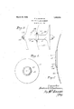
Fig. 1 is a plan or face view of a disk constructed according to my invention.
Fi re 2 is a diametrical section through the 'sk. V
Figure 3 is a view of the disks as assem- Serial No. 585,364.
bled in a ang, a portion of the central disk being bro en away to show the relation of the spool heads to the disk center.
The disk of my invention is formed from plate steel of uniform thickness and of any gage ordinarily employed in disk manufacturing. The main body 10 of the disk does not differ in shape from that of ordinary disks, but the central portion is formed with a pressed out or offset hub portion 11 formed by forcing metal of the disk outwardly at the back, thus forming a saucer-shaped depression in the face of the disk. This depression has a plane or flat floor corresponding in area to that of the spool heads between which the disks are to be clamped and has a diameter approximately one-fourth that of the disk. This flat portion is perforated at its center, which is the axis of the disk, as at 12, for the reception of a supporting shaft 13. This perforation may be either polygonal or round according as the disks are to turn with the shaft or on it. Between the central or hub portion and the main body of the disk, the metal is crimped or corrugated to describe a gradual reverse or ogee curve, as at 14 (Fig. 2), thus presenting on the face of the disk a rounded shoulder 15 having a comparatively long radius of curvature, and on the back of the disk a second rounded shoulder 16 having a shorter radius of curvature. As the flat bottom of the depressionll is to be of the same diameter as the supporting element or flange of the spacing spools to be used, the supportin elements or flanges in engagement with t e disk will extend to the margin of the flat portion and preferably will enga e its entire area and reach to the edge 0 the zone occupied by the curved portion 14.v In the species of my in vention here described it is important that the metal forming the sides of the depression 11 be given the proper curve and that the reverse curvature of the portions or shoulders 15, 16 shall be neither too abrupt nor too flat. It is also important that the metal of the disk in the zone immediately surrounding the spool heads of the assembled disk gang shall have a certain degree of resiliency in order that the highest resistance to center breakage of the disk may be obtained. I have discovered that the correct degree of resiliency to secure this result in a 16 inch. disk of standard curvature is produced by such a reversely curved or substantially corrugated circular portion as that shown in the drawings. This corrugated portion may be considered as having the face shoulder 15 and the back shoulder 16. For example, in the ordinary harrow disk of approximately 16 inches in diameter, the curve of the shoulder 15 should be on a radius of close to 1 inches and that of the shoulder 16 on a radius of approximately of an inch, while the flat center to 'be occupied by the clamping elements should be about four inches in diameter. The zone of deformation within which. these curves lie is, therefore, narrow, the total diameterof the pressed out portion on the convex side of the disk being only approxi mately one-third the diameter of the entire disk which, therefore, retains the shape and soil turning characteristics of the ordinary earth working disk throughout its effective area.
Disks constructed according to my invention are mounted in gangs in the usual manner on a shaft or axle 13 between spacing spools 17. the spools and disks being drawn up and tightly clamped. but, owing to the fact that the bottom of the hub por-- tion or cepression 11 on the disks is preferably flat, the spool ends or heads are also made flat and the necessity for grinding the spool ends to fit a concave-convex disk, as has heretofore been done, is eliminated, thereby further lessening the cost of manufacture and giving an improved gang construction.
With the construction and arrangement of disks described, the working thrusts acting on the face of the disk near its periphery are not concentrated in the metal immediately surrounding the edges of the spool ends, thereby causing crystallization at this point and parting of the metal, as has here tofore happened, the bent portion adjacent the edge of the spool head in my improved construction acting to change the direction of thrust and diffuse the strain throughout a greater area of the metal in the disk immediately surrounding the hub'thus greatly increasing its endurance and making it pos sible for the disk to withstand working strains indefinitely.
WVhile I have described one embodiment of my invention, modifications therefrom are possible within the scope of the following claims.
Iclaim as my invention:
1. As an article of manufacture, an earth Working disk with the greater part of its radial extent of ordinary concave-convex form and having asmaller central. hub p013 tion, corresponding in shape and size to conventional supporting spool heads, pressed out and forming a protrusion on its convex side, said central hub portion being delimited by a narrow zone Within which the metal of the disk is crimped.
2. As an article of manufacture, an earth working disk having a main or body portion of ordinary concavo convex -form and formed'with ahub portion pressed out to form a protrusion on its convex side delimited by a zone within which the metal of the disk is crimped, the diameter of said hub portion and crimped zone together being approximately one-third the diameter of the disk.
3. As an'article of manufacture, a disk for earth working implements having a main or body portion of ordinary concave-convex form and provided with a lnihportion delimited by a zone in which the metal of the disk is bent on a reverse curve, said hub forming a protrusion on the convex side of the disk. the width of the area within said zone being approximately one fourth that of the disk and corresponding to that of disk supporting heads of; standard type.
4. As an article of manufacture, a disk for earth working implements having a, main portion or body of ordinary concavoconvex form and provided with a hub portion ofthcsame thickness as the disk and consisting of a flattened area delimited by a zone in which the metal of the disk is bent on a reverse curve, saidhub portion forming a protrusion on the convex side of the disk, the width of said, flattened area being approximately one fourth that of the, disk andcorresponding to thatof disk supporting heads of standardtype.
5. A disk implement comprising an ordiT nary concavo-convex disk having an integral,
fiat hub portion approximately one. fourth the width of thedisk pressed out atlthe back of the disk, themetalsurrounding said flat. portlon merging with the body of the disk.
on a reverse curve, whereby a saucer shaped depression is formed in theface of the disk, and supporting means forthedi'sk compris's ing clamping elements engaging the opposite faces of saidflatportion and occupying. the entire area thereof.
6.. In a disleimplcm-cnt, an ordinary con cave-convex disk, having. an integral flat hub, portion otfsetrearwardly from the convex side of the disk with themetal'aroundthe" margin of saidfiatportio'n reversely curved i to provide a resilient zonesurrounding it, said fiat portion being approximately [one fourth the widthof the disk, and supporting means for the diskcomprising spools engag-f ing the opposite surfaces-of said flat portion.
and having portions extending to the margin thereof.
7. Ina disk implement, a. metallic. earth working. disk having an outer annular portion constituting the greater part of its radial extent .ofzstandard curvature, the
lit)
ltill metal of the disk in a narrow annular zone inwardly of said circumferential portion bein shaped on a reverse curve producing substantially a circular corrugation and constituting means for promoting the maximum resistance to center breakage by the strains of ordinary service, the portion of the disk surrounded by the circular corrugation being fiat, the diameter of this flat portion being approximately one-fourth of the diameter of the whole disk, and supporting means for the disk comprising spacing spools having heads with flat ends engaging the opposite sides of the flat portion of the disk and occupying all of the flat portion.
8. In a disk implement, the combination of a concavo-convex earth working disk having a central hub portion pressed out to form a protrusion on its convex side delimited by a narrow zone within which the metal of the disk is crimped, a shaft engaging said hub portion, and a supporting spool on the shaft in clamping engagement with a face of said protruding hub portion, said spool having a head the periphery of which lies at the inner margin of said crimped zone.
9. In a disk implement, the combination of an earth working disk having its greater part of ordinary concavo-convex form and a relatively small central hub portion pressed out to form a protrusion on its convex side delimited by a narrow zone within which the metal of the disk is crimped, a shaft engaging said hub portion, and a supporting spool on the shaft in clamping engagement with a. face of said protruding hub ortion, said spool having a head the perip cry of which lies at the inner margin of said crimped zone.
10. In a disk implement, the combination of an earth Working disk with the greater part of its radial extent of ordinary concavoconvex form and having a relatively small central hub portion pressed out and forming a protrusion on its convex side, said central hub portion being delimited by a narrow zone within which an annular band of the metal of the disk lies in obtuse angular relation to the disk surfaces adjacent said zone, and disk supporting means occupying all that portion of the hub within said zone.
11. In a disk implement, the combination of a concavo-convex earth working disk having the greater part of its radial extent of standard curvature, a supporting spool head engaging a surface of the disk in a zone surrounding the disk axis, and means for reenforcing the disk against rupture by working stresses in the circumferential zone surrounding the spool head, comprising a curvilinear deformation in the metal of the disk formed within a narrow zone immediately surrounding the margin of the spool head.
In testimony whereof I aflix my signature.
FREDERICK A. BUGKNAM.
Publications (1)
| Publication Number | Publication Date |
|---|---|
| US1663239A true US1663239A (en) | 1928-03-20 |
Family
ID=3414728
Family Applications (1)
| Application Number | Title | Priority Date | Filing Date |
|---|---|---|---|
| US1663239D Expired - Lifetime US1663239A (en) | Frederick a |
Country Status (1)
| Country | Link |
|---|---|
| US (1) | US1663239A (en) |
Cited By (13)
| Publication number | Priority date | Publication date | Assignee | Title |
|---|---|---|---|---|
| US3690385A (en) * | 1969-09-09 | 1972-09-12 | Stanley Marian Weiss | Cultivating implements |
| US4246971A (en) * | 1977-11-22 | 1981-01-27 | Ralph Mckay Limited | Tillage discs |
| US4590869A (en) * | 1979-02-12 | 1986-05-27 | Deere & Company | Double disk opener assembly and disk blade therefor |
| WO2002019791A1 (en) * | 2000-09-04 | 2002-03-14 | Väderstad-Verken Ab | Disc |
| US20050189126A1 (en) * | 2004-02-27 | 2005-09-01 | Cooper Troy L. | Disk blade scrapers for tillage apparatus |
| US7143704B1 (en) | 2005-09-23 | 2006-12-05 | Cnh America Llc | Recessed disc opener and mounting assembly method and apparatus |
| USD621421S1 (en) * | 2007-09-27 | 2010-08-10 | Falk Henry J | Spading vertical-tillage tool comprised of multiple disk blades |
| US20120103642A1 (en) * | 2009-05-29 | 2012-05-03 | Vaderstad-Verken Aktiebolag | Disc for an agricultural implement |
| US20120168187A1 (en) * | 2009-02-16 | 2012-07-05 | Bakame Lazcano Lasa | Fast-action harrow-disc coupling |
| US20140299343A1 (en) * | 2013-04-04 | 2014-10-09 | Douglas G. Bruce | Disc and Coulter with Center Depression for Strength |
| US9545046B1 (en) | 2015-07-22 | 2017-01-17 | Osmundson Mfg Co | Agricultural drill/planter/coulter/disc blade with ribs for strength |
| US20210059092A1 (en) * | 2018-02-07 | 2021-03-04 | Deere & Company | Tillage machine and tillage disk for the same |
| US11540434B2 (en) | 2019-10-15 | 2023-01-03 | Cnh Industrial America Llc | Curved cultivating disc with a straight cutting edge portion |
-
0
- US US1663239D patent/US1663239A/en not_active Expired - Lifetime
Cited By (21)
| Publication number | Priority date | Publication date | Assignee | Title |
|---|---|---|---|---|
| US3690385A (en) * | 1969-09-09 | 1972-09-12 | Stanley Marian Weiss | Cultivating implements |
| US4246971A (en) * | 1977-11-22 | 1981-01-27 | Ralph Mckay Limited | Tillage discs |
| US4590869A (en) * | 1979-02-12 | 1986-05-27 | Deere & Company | Double disk opener assembly and disk blade therefor |
| WO2002019791A1 (en) * | 2000-09-04 | 2002-03-14 | Väderstad-Verken Ab | Disc |
| US20080006417A1 (en) * | 2004-02-27 | 2008-01-10 | Cnh America Llc | Disk Blade Scrapers for Tillage Apparatus |
| US20050189126A1 (en) * | 2004-02-27 | 2005-09-01 | Cooper Troy L. | Disk blade scrapers for tillage apparatus |
| US7290620B2 (en) * | 2004-02-27 | 2007-11-06 | Cnh America Llc | Disk blade scrapers for tillage apparatus |
| US20080000657A1 (en) * | 2004-02-27 | 2008-01-03 | Cnh America Llc | Disk Blade Scrapers for Tillage Apparatus |
| US20080000656A1 (en) * | 2004-02-27 | 2008-01-03 | Cnh America Llc | Disk Blade Scrapers for Tillage Apparatus |
| US20080000655A1 (en) * | 2004-02-27 | 2008-01-03 | Cnh America Llc | Disk Blade Scrapers for Tillage Apparatus |
| US7143704B1 (en) | 2005-09-23 | 2006-12-05 | Cnh America Llc | Recessed disc opener and mounting assembly method and apparatus |
| USD621421S1 (en) * | 2007-09-27 | 2010-08-10 | Falk Henry J | Spading vertical-tillage tool comprised of multiple disk blades |
| US20120168187A1 (en) * | 2009-02-16 | 2012-07-05 | Bakame Lazcano Lasa | Fast-action harrow-disc coupling |
| US8899345B2 (en) * | 2009-02-16 | 2014-12-02 | Bellota Agrisolutions, S.L. | Fast-action harrow-disc coupling |
| US20120103642A1 (en) * | 2009-05-29 | 2012-05-03 | Vaderstad-Verken Aktiebolag | Disc for an agricultural implement |
| US9107340B2 (en) * | 2009-05-29 | 2015-08-18 | Vaderstad-Verken Aktebolag | Disc for an agricultural implement |
| US20140299343A1 (en) * | 2013-04-04 | 2014-10-09 | Douglas G. Bruce | Disc and Coulter with Center Depression for Strength |
| US9545046B1 (en) | 2015-07-22 | 2017-01-17 | Osmundson Mfg Co | Agricultural drill/planter/coulter/disc blade with ribs for strength |
| US20210059092A1 (en) * | 2018-02-07 | 2021-03-04 | Deere & Company | Tillage machine and tillage disk for the same |
| US11882778B2 (en) * | 2018-02-07 | 2024-01-30 | Deere & Company | Tillage machine and tillage disk for the same |
| US11540434B2 (en) | 2019-10-15 | 2023-01-03 | Cnh Industrial America Llc | Curved cultivating disc with a straight cutting edge portion |
Similar Documents
| Publication | Publication Date | Title |
|---|---|---|
| US1663239A (en) | Frederick a | |
| US5620055A (en) | Plow disk of the type intended to be mounted free in rotation on a shaft integral with the frame of a plow | |
| US4077120A (en) | Dry shaver with floating peripherally supported shear plate | |
| US7874376B2 (en) | Fluted farming disc | |
| US2242586A (en) | Method of making blowers | |
| US3559748A (en) | Fluted coulter disc blade | |
| US4329118A (en) | Centrifugal blower wheels | |
| US20110240319A1 (en) | Shallow concavity scalloped disc blade | |
| US2575321A (en) | Rotary hoe disk | |
| US1444224A (en) | Agricultural-implement wheel | |
| US4246971A (en) | Tillage discs | |
| US3690385A (en) | Cultivating implements | |
| US2587837A (en) | Clutch plate | |
| EP3468333B1 (en) | Disc tool, agricultural implement comprising such a disc tool and method for manufacturing a disc tool | |
| US3084367A (en) | Rotary brush | |
| US20140299343A1 (en) | Disc and Coulter with Center Depression for Strength | |
| US9545046B1 (en) | Agricultural drill/planter/coulter/disc blade with ribs for strength | |
| US2836889A (en) | Cutting roller for culinary and like uses | |
| US2559232A (en) | Rotary hoe wheel | |
| US2796819A (en) | Rotary hoe wheel | |
| US1776851A (en) | Roller pulverizer | |
| US3357082A (en) | Method of making a turbine wheel | |
| US2028365A (en) | Rotary hoe | |
| US2043098A (en) | Spider for lawn mower cutting reels | |
| US1488824A (en) | Caster wheel |