US5620055A - Plow disk of the type intended to be mounted free in rotation on a shaft integral with the frame of a plow - Google Patents
Plow disk of the type intended to be mounted free in rotation on a shaft integral with the frame of a plow Download PDFInfo
- Publication number
- US5620055A US5620055A US08/524,155 US52415595A US5620055A US 5620055 A US5620055 A US 5620055A US 52415595 A US52415595 A US 52415595A US 5620055 A US5620055 A US 5620055A
- Authority
- US
- United States
- Prior art keywords
- disk
- plow
- disks
- axis
- rotation
- Prior art date
- Legal status (The legal status is an assumption and is not a legal conclusion. Google has not performed a legal analysis and makes no representation as to the accuracy of the status listed.)
- Expired - Lifetime
Links
Images


Classifications
-
- A—HUMAN NECESSITIES
- A01—AGRICULTURE; FORESTRY; ANIMAL HUSBANDRY; HUNTING; TRAPPING; FISHING
- A01B—SOIL WORKING IN AGRICULTURE OR FORESTRY; PARTS, DETAILS, OR ACCESSORIES OF AGRICULTURAL MACHINES OR IMPLEMENTS, IN GENERAL
- A01B15/00—Elements, tools, or details of ploughs
- A01B15/16—Discs; Scrapers for cleaning discs; Sharpening attachments
Definitions
- This invention relates to a plow disk intended to be mounted with several other disks of the same nature, free in rotation around a shaft integral with the frame of a plow, said shaft being parallel to the ground but inclined in relation to the direction of advance of the plow so as to impart a rotation movement to the disks during the displacement of the plow, the periphery of the disk seen parallel to its axis of rotation exhibiting the shape of blades.
- disks of known type are generally in the shape of a portion of a sphere of steel centered on their axis of rotation. They therefore form a cup at the bottom of which is their hub and thereby cause a partial turning over of the earth during the plowing.
- This invention aims particularly at eliminating these drawbacks.
- the plow disk is characterized by the fact that the leading edge of the blades progressively rotates about the axis by turning in the direction of rotation of the plow disk during its work.
- the blades have a width which decreases while moving away from the axis of rotation.
- This arrangement exhibits not only the advantage of preventing the formation of a sole because the depth of attack of the ground varies as the advance, but further that of more effectively breaking up the clods of earth.
- the generatrix of the plow disk consists of a curve or a concave polygon whose one end is on the periphery of the disk and whose other end is near its center, said generatrix being entirely located on a single side of its tangent which is perpendicular to the axis of rotation of the disk, said tangent being in contact with the generatrix at a point away from its ends.
- the generatrix of a surface in revolution is the line whose motion generates the surface of revolution.
- the generatrix of the disk is the half cross-section of said disk with a plane containing the axis of rotation of said disk. In FIGS. 2-5 the cross-section of the disk of FIG.
- FIG. 1 is clearly represented by a plane passing through the center of the disk.
- the cross-section comprises a central part perpendicular to the axis of rotation followed by two inclined parts corresponding to the frusto-conical shape of the periphery of the disk.
- the cross-section of FIG. 3 is substantially curved.
- Half the cross-sections of FIGS. 4 and 5 are substantially toroidal.
- any of the FIGS. 2-5 if one considers a plane located on the left side of the figures, said plane being tangential to the cross-section, it is obvious that any part of the cross-section of the disk is located on the same side of said tangential plane.
- the tangential plane meets the cross-section in the vicinity of the center.
- the tangential plane meets the cross-section along a circle which is about half way between the center and the periphery of the disk.
- the tangential plane meets the cross-section along a circle which is closer to the periphery of the disk than to the center of the disk.
- This particular shape of the disk makes it possible to increase considerably its diameter while correctly folding back the upper part of the earth which is plowed.
- the two ends of the concave generatrix of the disk can be found in the same plane but it can be otherwise and according to a preferred embodiment, the end of the generatrix which is located in the vicinity of the axis of the disk is offset to the front in the direction of the advance of the plow.
- a plow disk according to the invention can be in the form of a surface similar to a torus portion delimited by a plane perpendicular to its axis or preferably by two planes, the plane delimiting the outside periphery of the disk being--in relation to the direction of working--in back of the plane perpendicular to the axis that the internal periphery of the disk delimits in the vicinity of its hub.
- This invention also has as its object a plow characterized by the fact that it comprises disks exhibiting the characteristics described above, and more particularly such a plow in which the blades of two adjacent disks are offset angularly by a predetermined value, for example by an angle between about 10° and 30°, and preferably between 15° and 20°.
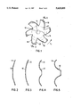
- FIG. 1 is a view in elevation of an embodiment of the plow disk according to the invention
- FIGS. 2A-5A are sections along II--II of four variant embodiments of the disk of FIGS. 1, 2B-5B are perspective views of FIGS. 2A-5A and
- FIGS. 2-5 are sectional views taken along line II--II of FIG. 1 showing four variant embodiments of the disk, and
- FIG. 6 represents a plow equipped with disks according to the invention.
- FIG. 7 is a top view of a plurality of disks inverted on a common shaft.
- the plow disk of FIG. 1 comprises at its central part a pierced hole (16) making it possible to mount it in the known way on a shaft integral with the frame of a plow, a shaft around which it can freely turn.
- the plow disk according to the invention comprises a series of blades 13 on its periphery, for example between three and 10 blades, preferably an odd number.
- Each blade 13 comprises a cutting leading edge 14 and a trailing edge 15 having the shape of lefthand screws, because of the concavity of the plow disk, but which seem plane in the elevation view in the direction of the axis of rotation 16 of the disk.
- Convex leading edges 14 progressively move away from axis 16 in the direction of rotation F1 that the disks adopt when they are driven by the advance of the plow.
- trailing edges 15 are concave and the crosswise dimension of each blade 13 decreases between its root zone 17 and its end 18.
- edges 14 and 15 can consist of arcs of ellipses, axis 16 being able, for example, to be one of the focal points of the arcs of ellipses 14.
- the plow disk according to the invention exhibits a section in the shape of a truncated cone, while in the variant of FIG. 3 it exhibits a section having the shape of a portion of a sphere.
- FIG. 4 is a cross-sectional view having a central circular flat portion surrounded by a toroidal surface portion obtained by a torus section by the plane of the flat circular portion where the toroidal portion surrounds the disk.
- FIG. 5 is similar to FIG. 4 with the toroidal surface portion delimited by two different planes, both of which are perpendicular to the axis. One plane delimits the outer periphery of the disk on one side of the torus while the other plane delimits the connection of the flat circular portion, and is located in the vicinity of the middle of the torus.
- the disks described above can be made, for example, by forming or by molding, and have a diameter between 45 cm and 150 cm or more.
- a disk set 31 is seen in FIG. 6, mounted integral with a rotation shaft 32.
- Shaft 32 is mounted free in rotation on the frame (not shown) of the plow, so as to be inclined in relation to its direction of advance.
- Each disk in the present case, is in the shape of five adjacent blades 13, each blade having its leading edge 14 which progressively moves away from the shaft while turning in the direction of rotation of the disk during its work.
- disks 31a and 31b are offset by an angle a which, in the present case, is approximately equal to 18°.
- this embodiment of discs includes a flat disk a provided with a central bore 16.
- This flat disk is surrounded by a crown b constituted by a frusto-conical surface.
- a cross section of this disk represented on FIG. 2B is made up of a linear portion perpendicular to the axis, with the linear portion being elongated at its ends by two inclined linear portions corresponding to the frusto-conical surface b.
- FIG. 3A a portion of a hollow sphere is depicted which has been cut by a plane.
- the axial cross section of the disk is part of a circle as represented by FIG. 3B.
- FIG. 4A shows a central circular flat portion b with the bore 16 for fixing the disk on the shaft.
- This disk b is surrounded by a toroidal surface portion e obtained by a torus c section by the plane d of the flat circular portion b, where the toroidal portion e surrounds the disk b.
- the last embodiment shown in FIG. 5A is similar to the embodiment in FIG. 4A, where the main difference is that the toroidal surface portion e is delimited by two different planes d1 and d2, both of which are perpendicular to the axis.
- the plane d1 delimits the outer periphery of the disk on one side of the torus while the plane d2 delimits the connection of the flat circular portion b and is located in the vicinity of the middle plane of the torus.
- FIGS. 2A-5A cannot show the cuts providing the blades 13 of the disc.
- the foregoing FIGS. 2-5 are represented by the line II--II on FIG. 1.
Abstract
This invention relates to a Plow Disk intended to be mounted with several disks of the same nature, free in rotation around a shaft integral with the frame of a plow, the shaft being parallel to the ground but inclined in relation to the direction of advance of the plow so as to impart a rotation movement to the disks during displacement of the plow, the periphery of the disk seen parallel to its axis of rotation exhibiting the shape of the blades.
Description
This application is a continuation of application Ser. No. 08/104,476 filed on Jul. 28, 1993, now abandoned; which is a continuation of Ser. No. 08/773,880, filed as PCT/FR90/00313, May 2, 1990 published as WO90/13217, Nov. 15, 1990, now abandoned.
This invention relates to a plow disk intended to be mounted with several other disks of the same nature, free in rotation around a shaft integral with the frame of a plow, said shaft being parallel to the ground but inclined in relation to the direction of advance of the plow so as to impart a rotation movement to the disks during the displacement of the plow, the periphery of the disk seen parallel to its axis of rotation exhibiting the shape of blades.
These disks of known type are generally in the shape of a portion of a sphere of steel centered on their axis of rotation. They therefore form a cup at the bottom of which is their hub and thereby cause a partial turning over of the earth during the plowing.
These plow disks as described in document U.S. Pat. No. 2,034,579 comprise notches on their periphery. They are not entirely satisfactory because, on the one hand, they have a tendency to collect and catch on the plants that are growing on the surface of the plowed ground and, on the other hand, the surface of the plowed ground does not always appear with the structure that it is desired to impart to it.
Another drawback of known plow disks of said type resides in the fact that they form a sole in the ground, i.e., they create a sharp separation surface between the part of the ground which is plowed and which is consequently loose, and the unplowed and consequently hard part.
This invention aims particularly at eliminating these drawbacks.
According to the invention, the plow disk is characterized by the fact that the leading edge of the blades progressively rotates about the axis by turning in the direction of rotation of the plow disk during its work.
Preferably, the blades have a width which decreases while moving away from the axis of rotation.
This arrangement exhibits not only the advantage of preventing the formation of a sole because the depth of attack of the ground varies as the advance, but further that of more effectively breaking up the clods of earth.
According to an embodiment of the invention, the generatrix of the plow disk consists of a curve or a concave polygon whose one end is on the periphery of the disk and whose other end is near its center, said generatrix being entirely located on a single side of its tangent which is perpendicular to the axis of rotation of the disk, said tangent being in contact with the generatrix at a point away from its ends. The generatrix of a surface in revolution is the line whose motion generates the surface of revolution. In the present invention, the generatrix of the disk is the half cross-section of said disk with a plane containing the axis of rotation of said disk. In FIGS. 2-5 the cross-section of the disk of FIG. 1 is clearly represented by a plane passing through the center of the disk. In FIG. 2, the cross-section comprises a central part perpendicular to the axis of rotation followed by two inclined parts corresponding to the frusto-conical shape of the periphery of the disk. The cross-section of FIG. 3 is substantially curved. Half the cross-sections of FIGS. 4 and 5 are substantially toroidal. In any of the FIGS. 2-5, if one considers a plane located on the left side of the figures, said plane being tangential to the cross-section, it is obvious that any part of the cross-section of the disk is located on the same side of said tangential plane. In FIGS. 2 and 3, the tangential plane meets the cross-section in the vicinity of the center. In FIG. 4, the tangential plane meets the cross-section along a circle which is about half way between the center and the periphery of the disk. In FIG. 5, the tangential plane meets the cross-section along a circle which is closer to the periphery of the disk than to the center of the disk.
This particular shape of the disk makes it possible to increase considerably its diameter while correctly folding back the upper part of the earth which is plowed.
A better release of the plants growing on the surface of the plowed ground also results from it and therefore a better penetration and an easier rotation of the disks which thus work under much better conditions.
The two ends of the concave generatrix of the disk can be found in the same plane but it can be otherwise and according to a preferred embodiment, the end of the generatrix which is located in the vicinity of the axis of the disk is offset to the front in the direction of the advance of the plow.
By way of example, a plow disk according to the invention can be in the form of a surface similar to a torus portion delimited by a plane perpendicular to its axis or preferably by two planes, the plane delimiting the outside periphery of the disk being--in relation to the direction of working--in back of the plane perpendicular to the axis that the internal periphery of the disk delimits in the vicinity of its hub.
This invention also has as its object a plow characterized by the fact that it comprises disks exhibiting the characteristics described above, and more particularly such a plow in which the blades of two adjacent disks are offset angularly by a predetermined value, for example by an angle between about 10° and 30°, and preferably between 15° and 20°.
Other characteristics of the invention are given in the accompanying claims which must be considered as being part of this description.
Now, by way of nonlimiting example, some particular embodiments of the invention will be given with reference to the accompanying diagrammatic drawing in which:
FIG. 1 is a view in elevation of an embodiment of the plow disk according to the invention,
FIGS. 2A-5A are sections along II--II of four variant embodiments of the disk of FIGS. 1, 2B-5B are perspective views of FIGS. 2A-5A and
FIGS. 2-5 are sectional views taken along line II--II of FIG. 1 showing four variant embodiments of the disk, and
FIG. 6 represents a plow equipped with disks according to the invention.
FIG. 7 is a top view of a plurality of disks inverted on a common shaft.
The plow disk of FIG. 1 comprises at its central part a pierced hole (16) making it possible to mount it in the known way on a shaft integral with the frame of a plow, a shaft around which it can freely turn.
In the embodiment described, the plow disk according to the invention comprises a series of blades 13 on its periphery, for example between three and 10 blades, preferably an odd number.
Each blade 13 comprises a cutting leading edge 14 and a trailing edge 15 having the shape of lefthand screws, because of the concavity of the plow disk, but which seem plane in the elevation view in the direction of the axis of rotation 16 of the disk.
Convex leading edges 14 progressively move away from axis 16 in the direction of rotation F1 that the disks adopt when they are driven by the advance of the plow.
In the embodiment shown, trailing edges 15, on the other hand, are concave and the crosswise dimension of each blade 13 decreases between its root zone 17 and its end 18.
Seen in plan as in FIG. 1, edges 14 and 15 can consist of arcs of ellipses, axis 16 being able, for example, to be one of the focal points of the arcs of ellipses 14.
In the variant of FIG. 2, the plow disk according to the invention exhibits a section in the shape of a truncated cone, while in the variant of FIG. 3 it exhibits a section having the shape of a portion of a sphere.
FIG. 4 is a cross-sectional view having a central circular flat portion surrounded by a toroidal surface portion obtained by a torus section by the plane of the flat circular portion where the toroidal portion surrounds the disk. FIG. 5 is similar to FIG. 4 with the toroidal surface portion delimited by two different planes, both of which are perpendicular to the axis. One plane delimits the outer periphery of the disk on one side of the torus while the other plane delimits the connection of the flat circular portion, and is located in the vicinity of the middle of the torus.
The disks described above can be made, for example, by forming or by molding, and have a diameter between 45 cm and 150 cm or more.
A disk set 31 is seen in FIG. 6, mounted integral with a rotation shaft 32.
Each disk, in the present case, is in the shape of five adjacent blades 13, each blade having its leading edge 14 which progressively moves away from the shaft while turning in the direction of rotation of the disk during its work.
It is seen that two adjacent disks, for example disks 31a and 31b are offset by an angle a which, in the present case, is approximately equal to 18°.
This offsetting of 18°, associated with the fact that the disks comprise five blades, causes the position of the disks on shaft 32 to be identical to itself every four disks, two disks 31a and 31e having the same angular offset being separated by three disks 31b, 31c, and 31d.
Consequently, every 18° of rotation of the set of disks 31, one disk in four attacks the ground, thus rendering the operation of the plow almost without vibration.
Referring to FIG. 2A, this embodiment of discs includes a flat disk a provided with a central bore 16. This flat disk is surrounded by a crown b constituted by a frusto-conical surface. It is clear that a cross section of this disk represented on FIG. 2B is made up of a linear portion perpendicular to the axis, with the linear portion being elongated at its ends by two inclined linear portions corresponding to the frusto-conical surface b.
Referring to FIG. 3A, a portion of a hollow sphere is depicted which has been cut by a plane. The axial cross section of the disk is part of a circle as represented by FIG. 3B.
The third embodiment shown in FIG. 4A shows a central circular flat portion b with the bore 16 for fixing the disk on the shaft. This disk b is surrounded by a toroidal surface portion e obtained by a torus c section by the plane d of the flat circular portion b, where the toroidal portion e surrounds the disk b.
The last embodiment shown in FIG. 5A is similar to the embodiment in FIG. 4A, where the main difference is that the toroidal surface portion e is delimited by two different planes d1 and d2, both of which are perpendicular to the axis. The plane d1 delimits the outer periphery of the disk on one side of the torus while the plane d2 delimits the connection of the flat circular portion b and is located in the vicinity of the middle plane of the torus.
FIGS. 2A-5A cannot show the cuts providing the blades 13 of the disc. The foregoing FIGS. 2-5 are represented by the line II--II on FIG. 1.
Claims (10)
1. A plow disk for mounting with a plurality of disks of the same nature on a frame of a plow, free in rotation about an axis parallel to the ground, but angled relative to a direction of advance of said plow in order to impart a movement of rotation to said plurality of disks during advance of said plow, each of said disks having a periphery constituted by a plurality of blades each comprising:
a first convex leading cutting edge having an inner extremity directed toward a center of said disk and an outer extremity at said periphery of said disk, a shape of said first convex leading cutting edge being such that when going from said inner extremity to said outer extremity a radial line toward said center of said disk is always moving angularly in a same direction,
a second cutting edge adjacent to said first convex leading cutting edge, a shape of which is substantially arcuate with its center located at said center of said disk, the length of said second arcuate cutting edge being substantially shorter than the length of said first convex leading cutting edge,
a back concave trailing edge adjacent to said second arcuate cutting edge which is directed substantially in the direction of said center of said disk,
the length of said second cutting edge being substantially smaller than a distance between said second cutting edges of two adjacent blades,
each blade having a crosswise dimension which decreases while moving away from said axis of rotation, and
a position of said disk on said plow being such that a first convex leading cutting edge of each blade is directed toward said direction of advance of said plow when said blade enters the ground.
2. A plow disk according to claim 1, wherein a cross section of the disk in a plane containing the axis of said disk is a central flat portion surrounded by a toroidal surface portion with said central flat portion being perpendicular to the axis of said disk.
3. A plow disk according to claim 2 wherein the periphery and the center of the disk are located substantially in the same plane, perpendicular to the axis of rotation of the disk.
4. A plow disk according to claim 2 wherein the periphery of the disk is located in a plane perpendicular to the axis of the disk which is substantially different from the plane perpendicular to the axis of the disk containing the central part of said disk.
5. A plow disk according to claim 2 wherein the cross section of said disk has substantially the shape of a portion of an arc.
6. A plow disk according to claim 2 wherein the cross section of the disk is substantially the shape of a frusto-conical surface.
7. A disk plow comprises a plurality of disks according to claim 1, said disks being integral with a shaft turning free in rotation around an axis parallel to the ground while being inclined in relation to the direction of advance of the plow.
8. A disk plow according to claim 7, wherein the blades of two adjacent disks are angularly offset by a predetermined value.
9. A disk plow according to claim 8, wherein the blades of two adjacent disks are offset by about 10° to 30°.
10. A disk plow according to claim 7, wherein the blades of two adjacent disks are angularly offset by 15° to 20°.
Priority Applications (1)
| Application Number | Priority Date | Filing Date | Title |
|---|---|---|---|
| US08/524,155 US5620055A (en) | 1989-05-02 | 1995-08-16 | Plow disk of the type intended to be mounted free in rotation on a shaft integral with the frame of a plow |
Applications Claiming Priority (7)
| Application Number | Priority Date | Filing Date | Title |
|---|---|---|---|
| FR8905815 | 1989-05-02 | ||
| FR8905815A FR2646585A1 (en) | 1989-05-02 | 1989-05-02 | Ploughing disc of the type intended to be mounted to rotate freely on a spindle secured to the chassis of a plough |
| FR8915558A FR2654892B2 (en) | 1989-05-26 | 1989-11-27 | DISC LABOR PLOW. |
| FR8915558 | 1989-11-27 | ||
| US77388091A | 1991-12-30 | 1991-12-30 | |
| US10447693A | 1993-07-28 | 1993-07-28 | |
| US08/524,155 US5620055A (en) | 1989-05-02 | 1995-08-16 | Plow disk of the type intended to be mounted free in rotation on a shaft integral with the frame of a plow |
Related Parent Applications (1)
| Application Number | Title | Priority Date | Filing Date |
|---|---|---|---|
| US10447693A Continuation | 1989-05-02 | 1993-07-28 |
Publications (1)
| Publication Number | Publication Date |
|---|---|
| US5620055A true US5620055A (en) | 1997-04-15 |
Family
ID=27446685
Family Applications (1)
| Application Number | Title | Priority Date | Filing Date |
|---|---|---|---|
| US08/524,155 Expired - Lifetime US5620055A (en) | 1989-05-02 | 1995-08-16 | Plow disk of the type intended to be mounted free in rotation on a shaft integral with the frame of a plow |
Country Status (1)
| Country | Link |
|---|---|
| US (1) | US5620055A (en) |
Cited By (49)
| Publication number | Priority date | Publication date | Assignee | Title |
|---|---|---|---|---|
| US5855246A (en) * | 1997-06-10 | 1999-01-05 | Bruce; Douglas G. | Agricultural disc |
| US6279666B1 (en) * | 1996-02-09 | 2001-08-28 | A.I.L., Inc. | Row crop debris clearing apparatus |
| US6554079B2 (en) | 2001-02-14 | 2003-04-29 | Douglas G. Bruce | Earth working disc with large notches |
| US20030225456A1 (en) * | 2000-05-01 | 2003-12-04 | Ek Steven W. | System and method for joint resurface repair |
| US20040015170A1 (en) * | 2000-05-01 | 2004-01-22 | Tallarida Steven J. | System and method for joint resurface repair |
| US20040148030A1 (en) * | 2000-05-01 | 2004-07-29 | Ek Steven W. | System and method for joint resurface repair |
| US20040230315A1 (en) * | 2000-05-01 | 2004-11-18 | Ek Steven W. | Articular surface implant |
| US20050154398A1 (en) * | 2002-12-03 | 2005-07-14 | Anthony Miniaci | Retrograde delivery of resurfacing devices |
| US20060190002A1 (en) * | 2000-05-01 | 2006-08-24 | Arthrosurface, Inc. | System and method for joint resurface repair |
| US7143704B1 (en) | 2005-09-23 | 2006-12-05 | Cnh America Llc | Recessed disc opener and mounting assembly method and apparatus |
| US20060283626A1 (en) * | 2000-09-27 | 2006-12-21 | Matsushita Electric Industrial Co., Ltd. | Resin board, manufacturing process for resin board, connection medium body, circuit board and manufacturing process for circuit board |
| US20070123921A1 (en) * | 2003-11-20 | 2007-05-31 | Arthrosurface, Inc. | Retrograde excision system and apparatus |
| US20070175644A1 (en) * | 2006-01-31 | 2007-08-02 | Trygve Skolness | Crust fracturing implement |
| US20070215366A1 (en) * | 2006-03-20 | 2007-09-20 | Cnh America Llc | Seedbed conditioning vertical tillage apparatus |
| US20080172125A1 (en) * | 2000-05-01 | 2008-07-17 | Arthrosurface Incorporated | System and Method for Joint Resurface Repair |
| US20090216285A1 (en) * | 2000-05-01 | 2009-08-27 | Arthrosurface, Inc. | Bone Resurfacing System and Method |
| US20090321096A1 (en) * | 2008-06-27 | 2009-12-31 | Winick Alan E | Finger wheel row cleaner |
| US20100006310A1 (en) * | 2004-09-28 | 2010-01-14 | Bauer Mark A | Zone tillage tool and method |
| US7713305B2 (en) | 2000-05-01 | 2010-05-11 | Arthrosurface, Inc. | Articular surface implant |
| EP2232971A1 (en) * | 2009-03-25 | 2010-09-29 | Jean-Charles Javerlhac | Plough disc and ploughing machine including at least one axle system provided with such disc |
| US7828853B2 (en) | 2004-11-22 | 2010-11-09 | Arthrosurface, Inc. | Articular surface implant and delivery system |
| US20110005785A1 (en) * | 2009-07-09 | 2011-01-13 | Bruce Douglas G | Notched coulter/disc and method of making same |
| US7901408B2 (en) | 2002-12-03 | 2011-03-08 | Arthrosurface, Inc. | System and method for retrograde procedure |
| US7914545B2 (en) | 2002-12-03 | 2011-03-29 | Arthrosurface, Inc | System and method for retrograde procedure |
| US8361159B2 (en) | 2002-12-03 | 2013-01-29 | Arthrosurface, Inc. | System for articular surface replacement |
| US8388624B2 (en) | 2003-02-24 | 2013-03-05 | Arthrosurface Incorporated | Trochlear resurfacing system and method |
| US8523872B2 (en) | 2002-12-03 | 2013-09-03 | Arthrosurface Incorporated | Tibial resurfacing system |
| US9066716B2 (en) | 2011-03-30 | 2015-06-30 | Arthrosurface Incorporated | Suture coil and suture sheath for tissue repair |
| US9283076B2 (en) | 2009-04-17 | 2016-03-15 | Arthrosurface Incorporated | Glenoid resurfacing system and method |
| US9358029B2 (en) | 2006-12-11 | 2016-06-07 | Arthrosurface Incorporated | Retrograde resection apparatus and method |
| US9468448B2 (en) | 2012-07-03 | 2016-10-18 | Arthrosurface Incorporated | System and method for joint resurfacing and repair |
| US9492200B2 (en) | 2013-04-16 | 2016-11-15 | Arthrosurface Incorporated | Suture system and method |
| USD780814S1 (en) * | 2015-07-28 | 2017-03-07 | Hard Metals Australia Pty Limited | Disc harrow blade |
| US9662126B2 (en) | 2009-04-17 | 2017-05-30 | Arthrosurface Incorporated | Glenoid resurfacing system and method |
| US9861492B2 (en) | 2014-03-07 | 2018-01-09 | Arthrosurface Incorporated | Anchor for an implant assembly |
| US10051772B2 (en) * | 2015-07-01 | 2018-08-21 | Brian E. Freed | Debris clearing device having teeth with sharpened leading edges |
| USD847871S1 (en) * | 2017-08-30 | 2019-05-07 | Hard Metals Australia Pty Limited | Disc harrow blade |
| USD857063S1 (en) * | 2017-08-02 | 2019-08-20 | F.P. Bourgault Tillage Tools Ltd. | Blade |
| US10390471B2 (en) | 2014-07-07 | 2019-08-27 | Douglas G. Bruce | Agricultural drill/planter/coulter/disc blade with sine wave edge |
| USD877781S1 (en) * | 2018-04-05 | 2020-03-10 | Deere & Company | Disk blade |
| US10624752B2 (en) | 2006-07-17 | 2020-04-21 | Arthrosurface Incorporated | Tibial resurfacing system and method |
| US10624748B2 (en) | 2014-03-07 | 2020-04-21 | Arthrosurface Incorporated | System and method for repairing articular surfaces |
| US10945743B2 (en) | 2009-04-17 | 2021-03-16 | Arthrosurface Incorporated | Glenoid repair system and methods of use thereof |
| US11160663B2 (en) | 2017-08-04 | 2021-11-02 | Arthrosurface Incorporated | Multicomponent articular surface implant |
| US11478358B2 (en) | 2019-03-12 | 2022-10-25 | Arthrosurface Incorporated | Humeral and glenoid articular surface implant systems and methods |
| US11607319B2 (en) | 2014-03-07 | 2023-03-21 | Arthrosurface Incorporated | System and method for repairing articular surfaces |
| USD992985S1 (en) * | 2020-12-21 | 2023-07-25 | Chad Sutherland | Cultivation device |
| US11712276B2 (en) | 2011-12-22 | 2023-08-01 | Arthrosurface Incorporated | System and method for bone fixation |
| USD1008318S1 (en) * | 2020-02-21 | 2023-12-19 | Sweco Products, Inc. | Rotor for tractor-towed agricultural implement |
Citations (25)
| Publication number | Priority date | Publication date | Assignee | Title |
|---|---|---|---|---|
| US380422A (en) * | 1888-04-03 | Combined seeder and harrow | ||
| US536094A (en) * | 1895-03-19 | John r | ||
| US672536A (en) * | 1900-10-24 | 1901-04-23 | John Rankin Newton | Cultivator-disk. |
| US882353A (en) * | 1907-10-03 | 1908-03-17 | Peter Speirs | Plow-disk and the like. |
| US1060280A (en) * | 1911-09-16 | 1913-04-29 | Sears Roebuck & Co | Disk harrow. |
| FR455691A (en) * | 1913-03-19 | 1913-08-06 | Auguste Louis Gourde | Rotary coulter plow |
| US1113241A (en) * | 1910-08-11 | 1914-10-13 | Frank B Niesz | Double disk harrow. |
| US1158110A (en) * | 1908-10-23 | 1915-10-26 | Albert E Cook | Plow-disk assembly. |
| US1214882A (en) * | 1915-05-21 | 1917-02-06 | Harley J Peck | Disk for disk plows. |
| US2034579A (en) * | 1934-05-19 | 1936-03-17 | Edward R Hurtig | Disk for agricultural implements |
| US2277622A (en) * | 1939-05-05 | 1942-03-24 | Deere & Co | Planter |
| US2528897A (en) * | 1947-01-10 | 1950-11-07 | Thomas H Mayfield | Cotton chopper and beet topping device |
| FR1024964A (en) * | 1950-05-05 | 1953-04-09 | Mounted reversible disc plow for tractors | |
| US2704970A (en) * | 1953-02-03 | 1955-03-29 | Greaves Joseph | Disk for seeders |
| US2746371A (en) * | 1953-01-08 | 1956-05-22 | Deere & Co | Plow disk |
| US2805534A (en) * | 1953-06-01 | 1957-09-10 | Robertson Jackson Perry | Composite fitting for folding lift-type disc harrow |
| FR1187337A (en) * | 1957-11-29 | 1959-09-09 | Discs for agricultural machines with multiple discs or for disc-type plows | |
| GB832431A (en) * | 1957-10-24 | 1960-04-13 | Antonio Juan Bautista Gheraldo | Disc for a disc plough or like agricultural machinery |
| US2949968A (en) * | 1956-05-01 | 1960-08-23 | Stoner Paul | Coulter assembly |
| US3005501A (en) * | 1958-09-10 | 1961-10-24 | Deere & Co | Disks and disk implements |
| US3621922A (en) * | 1970-05-08 | 1971-11-23 | Jacob O Hinken | Rolling fender |
| GB2023390A (en) * | 1978-06-26 | 1980-01-03 | Houle E R | Blade assembly for rotary trimmer |
| SU1033017A1 (en) * | 1982-03-31 | 1983-08-07 | Научно-Производственное Объединение По Эфиромасличным Культурам И Маслам | Implement for tilling soil |
| GB2122062A (en) * | 1982-06-16 | 1984-01-11 | Nat Res Dev | Rotary disc harrows |
| EP0162197A2 (en) * | 1984-05-22 | 1985-11-27 | Star Farm Machinery Mfg. Co., Ltd. | Disk plow |
-
1995
- 1995-08-16 US US08/524,155 patent/US5620055A/en not_active Expired - Lifetime
Patent Citations (25)
| Publication number | Priority date | Publication date | Assignee | Title |
|---|---|---|---|---|
| US380422A (en) * | 1888-04-03 | Combined seeder and harrow | ||
| US536094A (en) * | 1895-03-19 | John r | ||
| US672536A (en) * | 1900-10-24 | 1901-04-23 | John Rankin Newton | Cultivator-disk. |
| US882353A (en) * | 1907-10-03 | 1908-03-17 | Peter Speirs | Plow-disk and the like. |
| US1158110A (en) * | 1908-10-23 | 1915-10-26 | Albert E Cook | Plow-disk assembly. |
| US1113241A (en) * | 1910-08-11 | 1914-10-13 | Frank B Niesz | Double disk harrow. |
| US1060280A (en) * | 1911-09-16 | 1913-04-29 | Sears Roebuck & Co | Disk harrow. |
| FR455691A (en) * | 1913-03-19 | 1913-08-06 | Auguste Louis Gourde | Rotary coulter plow |
| US1214882A (en) * | 1915-05-21 | 1917-02-06 | Harley J Peck | Disk for disk plows. |
| US2034579A (en) * | 1934-05-19 | 1936-03-17 | Edward R Hurtig | Disk for agricultural implements |
| US2277622A (en) * | 1939-05-05 | 1942-03-24 | Deere & Co | Planter |
| US2528897A (en) * | 1947-01-10 | 1950-11-07 | Thomas H Mayfield | Cotton chopper and beet topping device |
| FR1024964A (en) * | 1950-05-05 | 1953-04-09 | Mounted reversible disc plow for tractors | |
| US2746371A (en) * | 1953-01-08 | 1956-05-22 | Deere & Co | Plow disk |
| US2704970A (en) * | 1953-02-03 | 1955-03-29 | Greaves Joseph | Disk for seeders |
| US2805534A (en) * | 1953-06-01 | 1957-09-10 | Robertson Jackson Perry | Composite fitting for folding lift-type disc harrow |
| US2949968A (en) * | 1956-05-01 | 1960-08-23 | Stoner Paul | Coulter assembly |
| GB832431A (en) * | 1957-10-24 | 1960-04-13 | Antonio Juan Bautista Gheraldo | Disc for a disc plough or like agricultural machinery |
| FR1187337A (en) * | 1957-11-29 | 1959-09-09 | Discs for agricultural machines with multiple discs or for disc-type plows | |
| US3005501A (en) * | 1958-09-10 | 1961-10-24 | Deere & Co | Disks and disk implements |
| US3621922A (en) * | 1970-05-08 | 1971-11-23 | Jacob O Hinken | Rolling fender |
| GB2023390A (en) * | 1978-06-26 | 1980-01-03 | Houle E R | Blade assembly for rotary trimmer |
| SU1033017A1 (en) * | 1982-03-31 | 1983-08-07 | Научно-Производственное Объединение По Эфиромасличным Культурам И Маслам | Implement for tilling soil |
| GB2122062A (en) * | 1982-06-16 | 1984-01-11 | Nat Res Dev | Rotary disc harrows |
| EP0162197A2 (en) * | 1984-05-22 | 1985-11-27 | Star Farm Machinery Mfg. Co., Ltd. | Disk plow |
Cited By (101)
| Publication number | Priority date | Publication date | Assignee | Title |
|---|---|---|---|---|
| US6279666B1 (en) * | 1996-02-09 | 2001-08-28 | A.I.L., Inc. | Row crop debris clearing apparatus |
| US5855246A (en) * | 1997-06-10 | 1999-01-05 | Bruce; Douglas G. | Agricultural disc |
| US20080172125A1 (en) * | 2000-05-01 | 2008-07-17 | Arthrosurface Incorporated | System and Method for Joint Resurface Repair |
| US20040015170A1 (en) * | 2000-05-01 | 2004-01-22 | Tallarida Steven J. | System and method for joint resurface repair |
| US7510558B2 (en) * | 2000-05-01 | 2009-03-31 | Arthrosurface, Inc. | System and method for joint resurface repair |
| US20090192516A1 (en) * | 2000-05-01 | 2009-07-30 | Arthrosurface Inc. | System and Method for Joint Resurface Repair |
| US20040230315A1 (en) * | 2000-05-01 | 2004-11-18 | Ek Steven W. | Articular surface implant |
| US9357989B2 (en) | 2000-05-01 | 2016-06-07 | Arthrosurface Incorporated | System and method for joint resurface repair |
| US20060190002A1 (en) * | 2000-05-01 | 2006-08-24 | Arthrosurface, Inc. | System and method for joint resurface repair |
| US9204873B2 (en) | 2000-05-01 | 2015-12-08 | Arthrosurface Incorporated | System and method for joint resurface repair |
| US7857817B2 (en) | 2000-05-01 | 2010-12-28 | Arthrosurface Inc. | System and method for joint resurface repair |
| US9055955B2 (en) | 2000-05-01 | 2015-06-16 | Arthrosurface Inc. | Bone resurfacing system and method |
| US8864827B2 (en) | 2000-05-01 | 2014-10-21 | Arthrosurface Inc. | System and method for joint resurface repair |
| US20100070045A1 (en) * | 2000-05-01 | 2010-03-18 | Arthrosurface Incorparated | System and Method for Joint Resurface Repair |
| US7713305B2 (en) | 2000-05-01 | 2010-05-11 | Arthrosurface, Inc. | Articular surface implant |
| US20030225456A1 (en) * | 2000-05-01 | 2003-12-04 | Ek Steven W. | System and method for joint resurface repair |
| US20040148030A1 (en) * | 2000-05-01 | 2004-07-29 | Ek Steven W. | System and method for joint resurface repair |
| US20090216285A1 (en) * | 2000-05-01 | 2009-08-27 | Arthrosurface, Inc. | Bone Resurfacing System and Method |
| US7604641B2 (en) | 2000-05-01 | 2009-10-20 | Arthrosurface Incorporated | System and method for joint resurface repair |
| US7618462B2 (en) | 2000-05-01 | 2009-11-17 | Arthrosurface Incorporated | System and method for joint resurface repair |
| US8540717B2 (en) | 2000-05-01 | 2013-09-24 | Arthrosurface Incorporated | System and method for joint resurface repair |
| US8177841B2 (en) | 2000-05-01 | 2012-05-15 | Arthrosurface Inc. | System and method for joint resurface repair |
| US8147559B2 (en) | 2000-05-01 | 2012-04-03 | Arthrosurface Incorporated | System and method for joint resurface repair |
| US20110152869A1 (en) * | 2000-05-01 | 2011-06-23 | Arthrosurface, Inc. | Bone Resurfacing System and Method |
| US7896883B2 (en) | 2000-05-01 | 2011-03-01 | Arthrosurface, Inc. | Bone resurfacing system and method |
| US7678151B2 (en) | 2000-05-01 | 2010-03-16 | Ek Steven W | System and method for joint resurface repair |
| US20060283626A1 (en) * | 2000-09-27 | 2006-12-21 | Matsushita Electric Industrial Co., Ltd. | Resin board, manufacturing process for resin board, connection medium body, circuit board and manufacturing process for circuit board |
| US6554079B2 (en) | 2001-02-14 | 2003-04-29 | Douglas G. Bruce | Earth working disc with large notches |
| US8663230B2 (en) | 2002-12-03 | 2014-03-04 | Arthrosurface Incorporated | Retrograde delivery of resurfacing devices |
| US20110196434A1 (en) * | 2002-12-03 | 2011-08-11 | Arthrosurface Incorporated | System and method for retrograde procedure |
| US9044343B2 (en) | 2002-12-03 | 2015-06-02 | Arthrosurface Incorporated | System for articular surface replacement |
| US10076343B2 (en) | 2002-12-03 | 2018-09-18 | Arthrosurface Incorporated | System for articular surface replacement |
| US8523872B2 (en) | 2002-12-03 | 2013-09-03 | Arthrosurface Incorporated | Tibial resurfacing system |
| US8361159B2 (en) | 2002-12-03 | 2013-01-29 | Arthrosurface, Inc. | System for articular surface replacement |
| US20050154398A1 (en) * | 2002-12-03 | 2005-07-14 | Anthony Miniaci | Retrograde delivery of resurfacing devices |
| US7896885B2 (en) | 2002-12-03 | 2011-03-01 | Arthrosurface Inc. | Retrograde delivery of resurfacing devices |
| US8926615B2 (en) | 2002-12-03 | 2015-01-06 | Arthrosurface, Inc. | System and method for retrograde procedure |
| US7901408B2 (en) | 2002-12-03 | 2011-03-08 | Arthrosurface, Inc. | System and method for retrograde procedure |
| US7914545B2 (en) | 2002-12-03 | 2011-03-29 | Arthrosurface, Inc | System and method for retrograde procedure |
| US8556902B2 (en) | 2002-12-03 | 2013-10-15 | Arthrosurface Incorporated | System and method for retrograde procedure |
| US9351745B2 (en) | 2003-02-24 | 2016-05-31 | Arthrosurface Incorporated | Trochlear resurfacing system and method |
| US9931211B2 (en) | 2003-02-24 | 2018-04-03 | Arthrosurface Incorporated | Trochlear resurfacing system and method |
| US11337819B2 (en) | 2003-02-24 | 2022-05-24 | Arthrosurface Incorporated | Trochlear resurfacing system and method |
| US10624749B2 (en) | 2003-02-24 | 2020-04-21 | Arthrosurface Incorporated | Trochlear resurfacing system and method |
| US8388624B2 (en) | 2003-02-24 | 2013-03-05 | Arthrosurface Incorporated | Trochlear resurfacing system and method |
| US7951163B2 (en) | 2003-11-20 | 2011-05-31 | Arthrosurface, Inc. | Retrograde excision system and apparatus |
| US20070123921A1 (en) * | 2003-11-20 | 2007-05-31 | Arthrosurface, Inc. | Retrograde excision system and apparatus |
| US8186450B2 (en) * | 2004-09-28 | 2012-05-29 | Enviromental Tillage Systems, Inc. | Zone tillage tool and method |
| US20100006310A1 (en) * | 2004-09-28 | 2010-01-14 | Bauer Mark A | Zone tillage tool and method |
| US8961614B2 (en) | 2004-11-22 | 2015-02-24 | Arthrosurface, Inc. | Articular surface implant and delivery system |
| US7828853B2 (en) | 2004-11-22 | 2010-11-09 | Arthrosurface, Inc. | Articular surface implant and delivery system |
| US7143704B1 (en) | 2005-09-23 | 2006-12-05 | Cnh America Llc | Recessed disc opener and mounting assembly method and apparatus |
| US7624814B2 (en) | 2006-01-31 | 2009-12-01 | Trygve Skolness | Crust fracturing implement |
| US20070175644A1 (en) * | 2006-01-31 | 2007-08-02 | Trygve Skolness | Crust fracturing implement |
| US20100038102A1 (en) * | 2006-01-31 | 2010-02-18 | Trygve Skolness | Crust Fracturing Implement |
| US7753133B2 (en) | 2006-01-31 | 2010-07-13 | Trygve Skolness | Crust fracturing implement |
| US7640995B2 (en) | 2006-03-20 | 2010-01-05 | Cnh America Llc | Seedbed conditioning vertical tillage apparatus |
| US20070215366A1 (en) * | 2006-03-20 | 2007-09-20 | Cnh America Llc | Seedbed conditioning vertical tillage apparatus |
| US11471289B2 (en) | 2006-07-17 | 2022-10-18 | Arthrosurface Incorporated | Tibial resurfacing system and method |
| US10624752B2 (en) | 2006-07-17 | 2020-04-21 | Arthrosurface Incorporated | Tibial resurfacing system and method |
| US10959740B2 (en) | 2006-12-11 | 2021-03-30 | Arthrosurface Incorporated | Retrograde resection apparatus and method |
| US10045788B2 (en) | 2006-12-11 | 2018-08-14 | Arthrosurface Incorporated | Retrograde resection apparatus and method |
| US9358029B2 (en) | 2006-12-11 | 2016-06-07 | Arthrosurface Incorporated | Retrograde resection apparatus and method |
| US20090321096A1 (en) * | 2008-06-27 | 2009-12-31 | Winick Alan E | Finger wheel row cleaner |
| US8596375B2 (en) | 2008-06-27 | 2013-12-03 | Alan E. Winick | Finger wheel row cleaner |
| EP2232971A1 (en) * | 2009-03-25 | 2010-09-29 | Jean-Charles Javerlhac | Plough disc and ploughing machine including at least one axle system provided with such disc |
| FR2943490A1 (en) * | 2009-03-25 | 2010-10-01 | Jean Charles Javerlhac | LABOR DISC AND LABOR DEVICE COMPRISING AT LEAST ONE TRAIN EQUIPPED WITH SUCH A DISK |
| US10945743B2 (en) | 2009-04-17 | 2021-03-16 | Arthrosurface Incorporated | Glenoid repair system and methods of use thereof |
| US11478259B2 (en) | 2009-04-17 | 2022-10-25 | Arthrosurface, Incorporated | Glenoid resurfacing system and method |
| US10478200B2 (en) | 2009-04-17 | 2019-11-19 | Arthrosurface Incorporated | Glenoid resurfacing system and method |
| US9662126B2 (en) | 2009-04-17 | 2017-05-30 | Arthrosurface Incorporated | Glenoid resurfacing system and method |
| US9283076B2 (en) | 2009-04-17 | 2016-03-15 | Arthrosurface Incorporated | Glenoid resurfacing system and method |
| US20110005785A1 (en) * | 2009-07-09 | 2011-01-13 | Bruce Douglas G | Notched coulter/disc and method of making same |
| US7878262B1 (en) * | 2009-07-09 | 2011-02-01 | Douglas G Bruce | Notched coulter/disc and method of making same |
| US9066716B2 (en) | 2011-03-30 | 2015-06-30 | Arthrosurface Incorporated | Suture coil and suture sheath for tissue repair |
| US11712276B2 (en) | 2011-12-22 | 2023-08-01 | Arthrosurface Incorporated | System and method for bone fixation |
| US11191552B2 (en) | 2012-07-03 | 2021-12-07 | Arthrosurface, Incorporated | System and method for joint resurfacing and repair |
| US10307172B2 (en) | 2012-07-03 | 2019-06-04 | Arthrosurface Incorporated | System and method for joint resurfacing and repair |
| US9468448B2 (en) | 2012-07-03 | 2016-10-18 | Arthrosurface Incorporated | System and method for joint resurfacing and repair |
| US9492200B2 (en) | 2013-04-16 | 2016-11-15 | Arthrosurface Incorporated | Suture system and method |
| US10695096B2 (en) | 2013-04-16 | 2020-06-30 | Arthrosurface Incorporated | Suture system and method |
| US11648036B2 (en) | 2013-04-16 | 2023-05-16 | Arthrosurface Incorporated | Suture system and method |
| US11607319B2 (en) | 2014-03-07 | 2023-03-21 | Arthrosurface Incorporated | System and method for repairing articular surfaces |
| US9861492B2 (en) | 2014-03-07 | 2018-01-09 | Arthrosurface Incorporated | Anchor for an implant assembly |
| US10624754B2 (en) | 2014-03-07 | 2020-04-21 | Arthrosurface Incorporated | System and method for repairing articular surfaces |
| US10575957B2 (en) | 2014-03-07 | 2020-03-03 | Arthrosurface Incoporated | Anchor for an implant assembly |
| US10624748B2 (en) | 2014-03-07 | 2020-04-21 | Arthrosurface Incorporated | System and method for repairing articular surfaces |
| US11083587B2 (en) | 2014-03-07 | 2021-08-10 | Arthrosurface Incorporated | Implant and anchor assembly |
| US9962265B2 (en) | 2014-03-07 | 2018-05-08 | Arthrosurface Incorporated | System and method for repairing articular surfaces |
| US9931219B2 (en) | 2014-03-07 | 2018-04-03 | Arthrosurface Incorporated | Implant and anchor assembly |
| US11766334B2 (en) | 2014-03-07 | 2023-09-26 | Arthrosurface Incorporated | System and method for repairing articular surfaces |
| US10390471B2 (en) | 2014-07-07 | 2019-08-27 | Douglas G. Bruce | Agricultural drill/planter/coulter/disc blade with sine wave edge |
| US10051772B2 (en) * | 2015-07-01 | 2018-08-21 | Brian E. Freed | Debris clearing device having teeth with sharpened leading edges |
| USD780814S1 (en) * | 2015-07-28 | 2017-03-07 | Hard Metals Australia Pty Limited | Disc harrow blade |
| USD857063S1 (en) * | 2017-08-02 | 2019-08-20 | F.P. Bourgault Tillage Tools Ltd. | Blade |
| US11160663B2 (en) | 2017-08-04 | 2021-11-02 | Arthrosurface Incorporated | Multicomponent articular surface implant |
| USD847871S1 (en) * | 2017-08-30 | 2019-05-07 | Hard Metals Australia Pty Limited | Disc harrow blade |
| USD877781S1 (en) * | 2018-04-05 | 2020-03-10 | Deere & Company | Disk blade |
| US11478358B2 (en) | 2019-03-12 | 2022-10-25 | Arthrosurface Incorporated | Humeral and glenoid articular surface implant systems and methods |
| USD1008318S1 (en) * | 2020-02-21 | 2023-12-19 | Sweco Products, Inc. | Rotor for tractor-towed agricultural implement |
| USD992985S1 (en) * | 2020-12-21 | 2023-07-25 | Chad Sutherland | Cultivation device |
Similar Documents
| Publication | Publication Date | Title |
|---|---|---|
| US5620055A (en) | Plow disk of the type intended to be mounted free in rotation on a shaft integral with the frame of a plow | |
| US4199926A (en) | Grass cutter and mulcher for rotary lawn mower | |
| JP4711717B2 (en) | Frequency-adjusting compressor stator blades and related methods | |
| JPH08105301A (en) | Reducing device of stress peak in anchor containing so-called "fir tree-shaped leg"-shaped root section of turbine blade | |
| US20110240319A1 (en) | Shallow concavity scalloped disc blade | |
| US6470662B1 (en) | Multiple blade cutting apparatus for rotary lawn mower | |
| US20050172601A1 (en) | Rotary lawn mower blade | |
| KR950005424A (en) | Circular saw blade | |
| US6523618B2 (en) | Tine assembly for a cultivator | |
| US5495897A (en) | Plow disk of the type intended to be mounted free in rotation on a shaft integral with the frame of a plow | |
| US2596574A (en) | Plow colter | |
| US1663239A (en) | Frederick a | |
| US5855246A (en) | Agricultural disc | |
| RU2085061C1 (en) | Plow disc and disk plow | |
| RU2046578C1 (en) | Disk plow | |
| US6739403B2 (en) | Tine assembly for a cultivator | |
| US4283819A (en) | Segment-shaped blade | |
| US2036820A (en) | Plow attachment | |
| AU2004206112A1 (en) | A cutting head for a brush cutter, edge trimmer or similar | |
| RU1782411C (en) | Root and tuber crop digging device | |
| RU157879U1 (en) | SPHERICAL CARVED DISC | |
| EP1021079A1 (en) | Multi-disc mowing machine | |
| SU1358798A1 (en) | Disk-type working member | |
| US3170522A (en) | Spading machine | |
| RU2287255C1 (en) | Mower knife section |
Legal Events
| Date | Code | Title | Description |
|---|---|---|---|
| STCF | Information on status: patent grant |
Free format text: PATENTED CASE |
|
| FEPP | Fee payment procedure |
Free format text: PAYOR NUMBER ASSIGNED (ORIGINAL EVENT CODE: ASPN); ENTITY STATUS OF PATENT OWNER: LARGE ENTITY |
|
| FPAY | Fee payment |
Year of fee payment: 4 |
|
| FPAY | Fee payment |
Year of fee payment: 8 |
|
| FPAY | Fee payment |
Year of fee payment: 12 |