US1663220A - Fuel-conditioning system - Google Patents
Fuel-conditioning system Download PDFInfo
- Publication number
- US1663220A US1663220A US698411A US69841124A US1663220A US 1663220 A US1663220 A US 1663220A US 698411 A US698411 A US 698411A US 69841124 A US69841124 A US 69841124A US 1663220 A US1663220 A US 1663220A
- Authority
- US
- United States
- Prior art keywords
- fuel
- air
- conditioning system
- pipe
- conditioning
- Prior art date
- Legal status (The legal status is an assumption and is not a legal conclusion. Google has not performed a legal analysis and makes no representation as to the accuracy of the status listed.)
- Expired - Lifetime
Links
Images
Classifications
-
- F—MECHANICAL ENGINEERING; LIGHTING; HEATING; WEAPONS; BLASTING
- F23—COMBUSTION APPARATUS; COMBUSTION PROCESSES
- F23K—FEEDING FUEL TO COMBUSTION APPARATUS
- F23K3/00—Feeding or distributing of lump or pulverulent fuel to combustion apparatus
Definitions
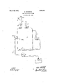
- This invention relates to a conditioning systen'i and it is especially useful in connection with pulverized coal burning installa tions, particularly those. of the 'direct fired Y type in which the coal is led from the pulverizer to the furnace.
- the conditioner comprises a vessel or tank 7 and a means for maintaining the fuel in suspen sion in air therein and in circulation.
- the pulverized fuel is led directly to the tank from the pulverizer (not shown) with practically only carrying air through the branch pipe 8 and the pipe 9, which latter is provided with a feeder 10 of any preferred design such as the star wheel type shown; or from a storage tank through the damper controlled branch 8.
- This feeder is preferably operated at speeds such as will replace fuel as fast as drawn form the conditioningtank to the furnace- Leading form the tank, preferably the up per part thereof, is a pipe 11 which enters another part, preferably-the bottom, and extends well within the tank where it'is provided with a plurality of upwardly directed nozzle or jet openings 12. Located in'this pipe is a suction fan 13. The operation of this fan, in starting, by way of illustration,-
- the fan drawsa mixture of coal and air from the top and discharges it into the bottom, keeping the fuel in suspension and in circulation.
- the fan may be small and uses little power as the operation is at atmospheric pressure, i. e. neither plus nor minus.
- a stream of the mixture may be drawn ofl at will through an outlet conduit or pipe 14, of which there may be one for each burner 15.
- This outlet preferably leads from an intermediate or middle portion of the tank,
- damper 18 is provided for control if needed.
- a fuel and air mixer including a conduit with fuel and air circulating means therein, one end of said conduit being connected into the chamber for the withdrawal of air and fuel therefrom, and the other end extending into the lower part of said chamber and having a plurality of upwardly directed discharge:
Landscapes
- Engineering & Computer Science (AREA)
- Chemical & Material Sciences (AREA)
- Combustion & Propulsion (AREA)
- Mechanical Engineering (AREA)
- General Engineering & Computer Science (AREA)
Description
March 20, 1928,
c SCHWARTZ FUEL counmomne SYSTEM Filed March 11. 1924 INVENTOR Q-MW A TTORNEYJ ill Patented Mar. 20, 1928.
' UNITED TENT "FFIc.
CARL SCHWARTZQOF 'Nnw RocI' ELLE, NEW YORK, ASSIGNOR To'INTEnNA IoNA i COMBUSTION ENGINEERING CORPORATION, A COBLPGRATION or DELAWARE.
- FUiEL-CQNDITIONING SYSTEM,
Applicationfiled March 1-1, 1924. Serial No. 698,411.
This invention relates to a conditioning systen'i and it is especially useful in connection with pulverized coal burning installa tions, particularly those. of the 'direct fired Y type in which the coal is led from the pulverizer to the furnace.
In such direct fired arrangements the coal mixed with air is conveyed to the burners from the pulverizerand'the operation of thepulverizer is impaired by virtue of the relatively large volume of air which is passed therethrough and, in addition, the passage of this air through the pulverizer represents work more or less uselessly performed, in; volving increased power costs and larger and more. expensive motors and apparatus. The mixture, also, is not uniform, which is an item of considerable importance. Deficiencies in mixture cannot be wholly and effectively compensated for by air admission at the furnace.
I aim to overcome these difficulties and to make direct firing-more practical and effective. I contemplate the proper conditioning of the fuel intermediate the pulverizer or other source of supply and the point of use, so that on the one hand, I may decrease power costs and the size of the pulverizer equipment and increase the effectiveness of the pulverizer and on the other hand burn the fuel more effectively and with less complication as to air supply and regulation.
More specifically, it is an object of my in- ;yention to provide a simple, effective conditioning apparatus, inexpensive to operate and maintain.
How the foregoing, together with such other objects as may hereinafter appear, or are incident to my invention, are obtained, I have disclosed in the following description and illustrated in preferred form in the drawing which is a diagrammatic illustration of my invention.
lVith reference to the drawing, the conditioner comprises a vessel or tank 7 and a means for maintaining the fuel in suspen sion in air therein and in circulation. The pulverized fuel is led directly to the tank from the pulverizer (not shown) with practically only carrying air through the branch pipe 8 and the pipe 9, which latter is provided with a feeder 10 of any preferred design such as the star wheel type shown; or from a storage tank through the damper controlled branch 8. This feeder is preferably operated at speeds such as will replace fuel as fast as drawn form the conditioningtank to the furnace- Leading form the tank, preferably the up per part thereof, is a pipe 11 which enters another part, preferably-the bottom, and extends well within the tank where it'is provided with a plurality of upwardly directed nozzle or jet openings 12. Located in'this pipe is a suction fan 13. The operation of this fan, in starting, by way of illustration,-
is to'draw air from the upper part of the tank and discharge it upwardly in the bottom of thetank, putting the pulverized coal in suspension in air. As the operation continues, the fan drawsa mixture of coal and air from the top and discharges it into the bottom, keeping the fuel in suspension and in circulation. The fan may be small and uses little power as the operation is at atmospheric pressure, i. e. neither plus nor minus.
A stream of the mixture may be drawn ofl at will through an outlet conduit or pipe 14, of which there may be one for each burner 15. This outlet preferably leads from an intermediate or middle portion of the tank,
the intake end 14L being turned downwardly to more effectively carry off the mixture. Any preferred arrangement may be employed to induce a flow through the pipe 14 and, in this instance, I have shown a fan 16, although other means may be well substituted.
As the stream is being drawn off, make up air is admitted through the inlet 17, which may well be merely open to the atmosphere, as the action will be substantially automatic for the reason that the feeder supplies fuel at the rate that the fuel is drawn out; and hence air enters 17 at the rate that it is drawn out. Stated another way the feeder and pipe 17 together supply coal and air at the rate coal and air are drawn off. A
damper 18 is provided for control if needed.
sign of the parts. With a uniform mixture and a uniform feed, which also results, the burning of the fuel may be more effectively accomplished, and the regulation of additional air admitted to the furnace for combustion simplified.
In shutting down, the damper 19 is closed and the damper 20 opened, whereby air is admitted to the pipe 14 and all feel drawn out therewith, leaving the pipe clean for starting up.
I claim: 1. In a pulverized fuel conditioning system, the combination of a source of fuel supply, a point of use, an interposed conditioning vessel having a fuel and air circulator adapted to maintain a mixture of the fuel with the air in the vessel, and a separate air inlet leading from the atmosphere to the conditioning vessel independent of the circulator. V
2. In a pulverized fuel conditioning system, the combination of a source of fuel supply, a point of use, an interposed conditioning apparatus with connections from the supply means and to the point of use, and
means whereby one of the connections may be exhausted of its contents.
3. In a pulverized fuel conditioning system, a source of supply, a point of use, and
in an upper region thereof; a fuel and air mixerincluding a conduit with fuel and air circulating means therein, one end of said conduit being connected into the chamber for the withdrawal of air and fuel therefrom, and the other end extending into the lower part of said chamber and having a plurality of upwardly directed discharge:
openings; and an outlet from the chamber for the mixed fuel and air.
In testimony whereof, I have hereunto signed my name.
CARL: SCHWARTZ 1
Priority Applications (1)
| Application Number | Priority Date | Filing Date | Title |
|---|---|---|---|
| US698411A US1663220A (en) | 1924-03-11 | 1924-03-11 | Fuel-conditioning system |
Applications Claiming Priority (1)
| Application Number | Priority Date | Filing Date | Title |
|---|---|---|---|
| US698411A US1663220A (en) | 1924-03-11 | 1924-03-11 | Fuel-conditioning system |
Publications (1)
| Publication Number | Publication Date |
|---|---|
| US1663220A true US1663220A (en) | 1928-03-20 |
Family
ID=24805123
Family Applications (1)
| Application Number | Title | Priority Date | Filing Date |
|---|---|---|---|
| US698411A Expired - Lifetime US1663220A (en) | 1924-03-11 | 1924-03-11 | Fuel-conditioning system |
Country Status (1)
| Country | Link |
|---|---|
| US (1) | US1663220A (en) |
Cited By (1)
| Publication number | Priority date | Publication date | Assignee | Title |
|---|---|---|---|---|
| EP0044095A1 (en) * | 1980-07-14 | 1982-01-20 | Paul Wurth S.A. | Method and apparatus for the uniform pneumatic conveyance of finely divided solids and application to the injection of solid fuels into a shaft furnace |
-
1924
- 1924-03-11 US US698411A patent/US1663220A/en not_active Expired - Lifetime
Cited By (1)
| Publication number | Priority date | Publication date | Assignee | Title |
|---|---|---|---|---|
| EP0044095A1 (en) * | 1980-07-14 | 1982-01-20 | Paul Wurth S.A. | Method and apparatus for the uniform pneumatic conveyance of finely divided solids and application to the injection of solid fuels into a shaft furnace |
Similar Documents
| Publication | Publication Date | Title |
|---|---|---|
| US1729763A (en) | Apparatus and method of fuel burning | |
| US2532740A (en) | Fuel burner provided with combustion gas recirculating means | |
| US1663220A (en) | Fuel-conditioning system | |
| US1885067A (en) | Fuel burner | |
| US1736675A (en) | Method of and means for burning fuel in regenerative furnaces | |
| US2853284A (en) | High velocity heater | |
| US2025331A (en) | Fuel burner | |
| US1955255A (en) | Air heater for pulverizers | |
| US2216117A (en) | Furnace | |
| US1550873A (en) | Combustion-promoting device | |
| US1332684A (en) | Method of furnace-heating | |
| US1700592A (en) | loepsinger | |
| US1931478A (en) | Combined gas and oil burner | |
| US1958265A (en) | Combustion chamber | |
| US1369200A (en) | Process of oxidizing fuel | |
| GB309641A (en) | Improvements in or relating to burners particularly for furnaces fired with pulverised fuel | |
| US3260227A (en) | System for drying and burning wet coal | |
| US2148202A (en) | Oil burner | |
| US1532647A (en) | Method of and apparatus for preparing, feeding, and burning pulverized fuel | |
| US2395417A (en) | Aircraft heating apparatus | |
| US2211637A (en) | Furnace | |
| USRE21878E (en) | Method and apparatus fob | |
| US738132A (en) | Furnace. | |
| US4455968A (en) | Boilers | |
| SU93532A1 (en) | Charcoal burner for locomotives |