US1663216A - Locomotive fire box - Google Patents
Locomotive fire box Download PDFInfo
- Publication number
- US1663216A US1663216A US633371A US63337123A US1663216A US 1663216 A US1663216 A US 1663216A US 633371 A US633371 A US 633371A US 63337123 A US63337123 A US 63337123A US 1663216 A US1663216 A US 1663216A
- Authority
- US
- United States
- Prior art keywords
- corners
- box
- boxes
- outside
- radius
- Prior art date
- Legal status (The legal status is an assumption and is not a legal conclusion. Google has not performed a legal analysis and makes no representation as to the accuracy of the status listed.)
- Expired - Lifetime
Links
- 230000003137 locomotive effect Effects 0.000 title description 11
- XLYOFNOQVPJJNP-UHFFFAOYSA-N water Substances O XLYOFNOQVPJJNP-UHFFFAOYSA-N 0.000 description 10
- 238000010276 construction Methods 0.000 description 5
- 238000004519 manufacturing process Methods 0.000 description 4
- 230000003467 diminishing effect Effects 0.000 description 2
- 238000000034 method Methods 0.000 description 2
- 238000012423 maintenance Methods 0.000 description 1
- 238000005406 washing Methods 0.000 description 1
Images
Classifications
-
- F—MECHANICAL ENGINEERING; LIGHTING; HEATING; WEAPONS; BLASTING
- F22—STEAM GENERATION
- F22B—METHODS OF STEAM GENERATION; STEAM BOILERS
- F22B13/00—Steam boilers of fire-box type, i.e. boilers where both combustion chambers and subsequent flues or fire tubes are arranged within the boiler body
- F22B13/06—Locomobile, traction-engine, steam-roller, or locomotive boilers
- F22B13/08—Locomobile, traction-engine, steam-roller, or locomotive boilers without auxiliary water tubes inside the fire-box
Definitions
- This invention relates to locomotive fire boxes and it has for one of its primary objects, increasing the rapidity of circulation through the box, making it possible to evaporate more water in less time, which is of great importance in view of the rapid development of locomotive power requirements.
- Another of the objects of the invention is.
- a further object of the invention is to'provide a construction in which it is possible to obtain tight seams with much less difficulty than heretofore and in which the maintenance cost is reduced.
- Still another object of. the invention is the provision of a construction which is simple to manufacture and in which assemblage is expedited and the process of manufacture generally cheapened.
- Fig. 1 is a longitudinal section through a locomotive fire box embodying my improvements; Fig. 1 is a section on the line 1-1 of Fig. 1; Fig. 2 is a section taken on the line 22 of Fig. 1; Fig. 3 is a diagrammatic longitudinal section illustrating the manner in which the inside fire box is inserted in the outside box; and Fig. l is a section taken on the line 4-4 of ances available when inserting the inside box.
- the reference number 7 denotes the boiler shell, and the reference letter A the inside fire box, and the reference letter the outside box or casing.
- the inside box A comprises a ue and throat sheet 8, the side sheets 9, the crown 10, and the back sheet 11.
- side box comprises the side sheets 12, the roof sheet 13, the back sheet or head lat and the Fig. 3 indicating the clearthe advan- The out- I Serial No. 633,371..
- the roof and crown and side sheets are pereferably composed of a single sheet suitably formed.
- This arrangement provides the usual front and rear water legs a and b, respectively, and the side water legs 0, closed at the bottom by the mud ring 17. It will be ob served, however, that the corners of the fire box are rounded and that the width oft-he space at the corners is greater than the width of the adjacent water spaces, to whichend the corners of the inside box are formed substantially on approximately the same radius as the corners of the outside box, or on a greater radius, the radius being in all cases, as shown, not less than the distance between the side sheets.
- the radii at a corner diminish upwardly so that the full area of the water spaces is maintained and their 'efi'i- (See theshading in ciency not cut down. Fig.
- this construction makes it possible to effectively wash down the sides of the water legs throughout and i also to inspect the stay bolts which tie the sheets together.
- the washout plugs 16 are provided for this purpose and are located about midway of the radius. Furthermore, the corners are easier to form and the seams do not come so close to the corners. In ordinary construction the seams lie very close to the corners withthe resultthat difliculty is experienced in securing tight scams. 7
- a still further and important advantage is that it is possible, as in the arrangement shown, to assemble the boxes and insert the inside box within the outside box without having to resort afterward'to riveting the back head in placeby use of patch bolts or hand riveting, which is both unsatisfactory and costly.
- the method of manufacture is substantially as follows: The outside casing, the throat sheet, the shell of the (not shown) boiler and the back head are riveted together in a hydraulic riveting machine. The inside box is riveted together in a separate operation and is then inserted in the opening at the bottom Thedotted lines in Fig. 3 indicate the manner in which this is brought about. The mud ring is then placed in position between the boxes and the boxes riveted thereto.
- boxes having materially rounded corners but with the radii at each bottom corner being struck from the same center it has not been possible to assemble the boxes separately and insert the inside box from below, as described and shown. It will be readily understood by those skilled in the art that this simplifies manufacture greatly.
- the mud ring is constructed so as to conform, i. e., the inside and outside curves at the corners are struck from the same center as the corners for the inside and outside boxes.
- V l/Vhat I claim is: V l.
- a locomotive fire box comprising the usual inside and outside boxes, the corners of the boxes, however, being materially rounded and formed on radii diminishing upwardly, the radius of the outside corners at the botof the outside box;
- tom being approximately equal to the radius of the inside corners at the bottom and both bottom radii being not less'than the distance between side sheets.
- a locomotive fire box comprising the usual inside and outside boxes, the corners of the boxes, however, rounded and formed on radii diminishing upwardly, the radius of the outside corners at the bottom being not in excess of the radius of the inside corners at the bottom and both bottom radii being not less than the distance between side sheets.
- a locomotive firebox comprising the usual inside and outside boxes, the corners of the boxes, however, being materially rounded with the radius or" the outside corners being not in excess of the radius of the inside corners and both radii being not less than the distance between. side sheets.
- a locomotive fire box comprising the usual inside and outside boxes, but said boxes, however, having materially rounded corners with the radius of the outside corners at the bottom being not in excess of the radius of the inside corners at the bottom.
Landscapes
- Engineering & Computer Science (AREA)
- Chemical & Material Sciences (AREA)
- Combustion & Propulsion (AREA)
- Physics & Mathematics (AREA)
- Thermal Sciences (AREA)
- Mechanical Engineering (AREA)
- General Engineering & Computer Science (AREA)
- Cookers (AREA)
Description
March 20, 1928. 1,663,216
' w. L. REID LOCOMOTIVE FIRE BOX Filed April 20, 1923 2 Sheets-Sheet 1 ATTORNEYS MarchZO, 1928.
w. L. REID v LOCOMOTIVE FIRE BOX Filed April 20, 1923 2 Sheets-Sheet 2 4 Mfg A TTORNEKS Patented Mar. 20, 1928.
WILLIAM L. REID, F LIMA, OHIO.
LOCOMOTIVE FIR-E BOX.
Application filed. April 20, 1923.
This invention relates to locomotive fire boxes and it has for one of its primary objects, increasing the rapidity of circulation through the box, making it possible to evaporate more water in less time, which is of great importance in view of the rapid development of locomotive power requirements.
Another of the objects of the invention is.
to facilitate the washing down of the sides of the water spaces and the mud ring and to make it possible to see along both water legs from the corners, for examination of the stay bolts.
A further object of the invention is to'provide a construction in which it is possible to obtain tight seams with much less difficulty than heretofore and in which the maintenance cost is reduced.
Still another object of. the invention is the provision of a construction which is simple to manufacture and in which assemblage is expedited and the process of manufacture generally cheapened.
I accomplish the foregoing, together with such other objects as may hereinafter appear, or are incident to my invention, by means ofa construction which I have illustrated in preferred form in the accompanying drawings, wherein:
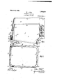
Fig. 1 is a longitudinal section through a locomotive fire box embodying my improvements; Fig. 1 is a section on the line 1-1 of Fig. 1; Fig. 2 is a section taken on the line 22 of Fig. 1; Fig. 3 is a diagrammatic longitudinal section illustrating the manner in which the inside fire box is inserted in the outside box; and Fig. l is a section taken on the line 4-4 of ances available when inserting the inside box.
This invention, generally considered, has to do with locomotive fire boxes of the round corner type. I am aware that such fire boxes have been manufactured heretofore, but, for reasons which will appear in connection with the description of the invention,
tages herein set forth were not present in such prior boxes. Referring now to Fig. 1, the reference number 7 denotes the boiler shell, and the reference letter A the inside fire box, and the reference letter the outside box or casing. The inside box A comprises a ue and throat sheet 8, the side sheets 9, the crown 10, and the back sheet 11. side box comprises the side sheets 12, the roof sheet 13, the back sheet or head lat and the Fig. 3 indicating the clearthe advan- The out- I Serial No. 633,371..
throat sheet 15.- The roof and crown and side sheets are pereferably composed of a single sheet suitably formed.
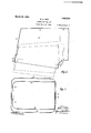
This arrangement provides the usual front and rear water legs a and b, respectively, and the side water legs 0, closed at the bottom by the mud ring 17. It will be ob served, however, that the corners of the fire box are rounded and that the width oft-he space at the corners is greater than the width of the adjacent water spaces, to whichend the corners of the inside box are formed substantially on approximately the same radius as the corners of the outside box, or on a greater radius, the radius being in all cases, as shown, not less than the distance between the side sheets. The radii at a corner diminish upwardly so that the full area of the water spaces is maintained and their 'efi'i- (See theshading in ciency not cut down. Fig. 1 and compare the radii of the rear corners in Figs l and 2.) Heretofore, in round-cornered fire boxes, the corners of the outside and inside boxes have been struck from substantially the same center or with an inner radius less than the outer radius and, therefore, have presented considerable resistance to flow or circulation of water. By my arrangment the resistance to flow from one water leg to the other is reduced to a minimum. I
In addition to t e advantage of obtaining more rapid circulation, this construction makes it possible to effectively wash down the sides of the water legs throughout and i also to inspect the stay bolts which tie the sheets together. The washout plugs 16 are provided for this purpose and are located about midway of the radius. Furthermore, the corners are easier to form and the seams do not come so close to the corners. In ordinary construction the seams lie very close to the corners withthe resultthat difliculty is experienced in securing tight scams. 7
A still further and important advantage is that it is possible, as in the arrangement shown, to assemble the boxes and insert the inside box within the outside box without having to resort afterward'to riveting the back head in placeby use of patch bolts or hand riveting, which is both unsatisfactory and costly.
In the box shown, the method of manufacture is substantially as follows: The outside casing, the throat sheet, the shell of the (not shown) boiler and the back head are riveted together in a hydraulic riveting machine. The inside box is riveted together in a separate operation and is then inserted in the opening at the bottom Thedotted lines in Fig. 3 indicate the manner in which this is brought about. The mud ring is then placed in position between the boxes and the boxes riveted thereto. Heretofore in boxes having materially rounded corners but with the radii at each bottom corner being struck from the same center, it has not been possible to assemble the boxes separately and insert the inside box from below, as described and shown. It will be readily understood by those skilled in the art that this simplifies manufacture greatly.
It will, of course, be understood that the mud ring is constructed so as to conform, i. e., the inside and outside curves at the corners are struck from the same center as the corners for the inside and outside boxes.
l/Vhat I claim is: V l. A locomotive fire box comprising the usual inside and outside boxes, the corners of the boxes, however, being materially rounded and formed on radii diminishing upwardly, the radius of the outside corners at the botof the outside box;
tom being approximately equal to the radius of the inside corners at the bottom and both bottom radii being not less'than the distance between side sheets.
2. A locomotive fire box comprising the usual inside and outside boxes, the corners of the boxes, however, rounded and formed on radii diminishing upwardly, the radius of the outside corners at the bottom being not in excess of the radius of the inside corners at the bottom and both bottom radii being not less than the distance between side sheets.
3. A locomotive firebox comprising the usual inside and outside boxes, the corners of the boxes, however, being materially rounded with the radius or" the outside corners being not in excess of the radius of the inside corners and both radii being not less than the distance between. side sheets.
4. A locomotive fire box comprising the usual inside and outside boxes, but said boxes, however, having materially rounded corners with the radius of the outside corners at the bottom being not in excess of the radius of the inside corners at the bottom.
' In testimony whereof, I. have hereunto signed my name. i
WILLIAM L. REID;
being materially
Priority Applications (1)
| Application Number | Priority Date | Filing Date | Title |
|---|---|---|---|
| US633371A US1663216A (en) | 1923-04-20 | 1923-04-20 | Locomotive fire box |
Applications Claiming Priority (1)
| Application Number | Priority Date | Filing Date | Title |
|---|---|---|---|
| US633371A US1663216A (en) | 1923-04-20 | 1923-04-20 | Locomotive fire box |
Publications (1)
| Publication Number | Publication Date |
|---|---|
| US1663216A true US1663216A (en) | 1928-03-20 |
Family
ID=24539372
Family Applications (1)
| Application Number | Title | Priority Date | Filing Date |
|---|---|---|---|
| US633371A Expired - Lifetime US1663216A (en) | 1923-04-20 | 1923-04-20 | Locomotive fire box |
Country Status (1)
| Country | Link |
|---|---|
| US (1) | US1663216A (en) |
-
1923
- 1923-04-20 US US633371A patent/US1663216A/en not_active Expired - Lifetime
Similar Documents
| Publication | Publication Date | Title |
|---|---|---|
| US1663216A (en) | Locomotive fire box | |
| US1774136A (en) | Combustion-chamber wall for steam boilers | |
| US2064123A (en) | Welded boiler construction | |
| US1822937A (en) | Locomotive boiler fire box | |
| US1712615A (en) | Locomotive boiler | |
| US1864601A (en) | Wall plate structure for furnaces | |
| US1636985A (en) | High-pressure steam boiler | |
| USRE17033E (en) | birchfield | |
| US1097830A (en) | Circulating-tube for steam-boilers. | |
| US2085089A (en) | Boiler | |
| US1712614A (en) | Locomotive boiler | |
| US1677427A (en) | Locomotive boiler | |
| US2058030A (en) | Retainer for fluids under pressure | |
| US1393741A (en) | Boiler | |
| US1708919A (en) | Locomotive boiler | |
| US1864600A (en) | Method of forming wall plate structures for furnaces | |
| US1814257A (en) | Locomotive boiler | |
| US1667112A (en) | Locomotive boiler | |
| US2289937A (en) | Locomotive firebox equipment | |
| US1704145A (en) | Method of repairing siphons | |
| US1408244A (en) | Boiler | |
| US1618829A (en) | Boiler | |
| US1159180A (en) | Steam-boiler. | |
| US2347004A (en) | Siphon | |
| US1728733A (en) | Fluid heater |