US1663207A - Engine ignition system - Google Patents
Engine ignition system Download PDFInfo
- Publication number
- US1663207A US1663207A US1663207DA US1663207A US 1663207 A US1663207 A US 1663207A US 1663207D A US1663207D A US 1663207DA US 1663207 A US1663207 A US 1663207A
- Authority
- US
- United States
- Prior art keywords
- circuit
- closers
- engine
- cam
- primary
- Prior art date
- Legal status (The legal status is an assumption and is not a legal conclusion. Google has not performed a legal analysis and makes no representation as to the accuracy of the status listed.)
- Expired - Lifetime
Links
Images
Classifications
-
- F—MECHANICAL ENGINEERING; LIGHTING; HEATING; WEAPONS; BLASTING
- F02—COMBUSTION ENGINES; HOT-GAS OR COMBUSTION-PRODUCT ENGINE PLANTS
- F02P—IGNITION, OTHER THAN COMPRESSION IGNITION, FOR INTERNAL-COMBUSTION ENGINES; TESTING OF IGNITION TIMING IN COMPRESSION-IGNITION ENGINES
- F02P5/00—Advancing or retarding ignition; Control therefor
- F02P5/04—Advancing or retarding ignition; Control therefor automatically, as a function of the working conditions of the engine or vehicle or of the atmospheric conditions
- F02P5/05—Advancing or retarding ignition; Control therefor automatically, as a function of the working conditions of the engine or vehicle or of the atmospheric conditions using mechanical means
- F02P5/06—Advancing or retarding ignition; Control therefor automatically, as a function of the working conditions of the engine or vehicle or of the atmospheric conditions using mechanical means dependent on engine speed
- F02P5/07—Centrifugal timing mechanisms
Definitions
- My invention has for its object to provide an ignition system-for internal combustion engines to produce high tension sparks at the spark plugs of the engine at high and low speeds of the engine.
- induction coils have characteristic time constants in which the maximum number of lines 0f force are produced by the primary coil in conjunction with a given currentintensity, and if the'circuit breaker of the ignition system opens the primary circuit to produce thespark'a't the spark plugs before the expiration of the time required for complete building up of the lines of force there is a corresponding reduction of the secondary current. .As a result no sparks may be produced when the primary circuit is broken .or if produced the sparks have no heat value and may not ignite the gaseous fuel in the cylinders of the engine.
- a pair of circuit closers are located in the systems involving the use of my invention which may be used to vary or to extend the period of closure of the primary circuit when the speed ofthe engine has increased sufliciently to make such increase desirable.
- the period of closure may be adj ustably extended. It may be automatically extending according to the speed of the engine or it may be extended by manual operation when the indicated speed reaches a certain point.
- the invention may be used in conjunction with ignition systems of different forms and in circuits having different self inductance.
- I have shown a system and a timer for controlling the period in which the primary circuit is closed.
- the system and the timer selected-for purposes of illustration are shown in the accompanying drawings and are described hereinafter.
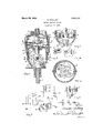
- Fig. 1 illustrates a vertical section of a timer that may be used in the application of my invention and which operates to close the circuit of one of the circuit closers.
- Fig. 2 is a view of a section taken on the plane of the line 2 2 indicated in Fig. 1.
- Fig. 3 illustrates a position of the governor means when the circuit of the circuit closer which it controls is closed.
- Fig. 4 is a side view of a contact that is closed by the governor of the timer.
- Fig. 5 is a view of a section taken on the plane of the line 5-5 indicated in Fig. 4.
- Fig. 6 illustrates the manner ⁇ in which the governor of the circuit closer shown'in Fig. 1 is counter-balanced, and the means whereby it is supported.
- Fig. 7 isa view of an ignition system for internal combustion engines wherein the parts are indicated diagrammatically.
- Fig. 8 indicates diagrammatically the closure periods as measured in the degrees of rotation .of the cam shaft of the engine.
- one circuit closer is operated by one cam point while the other is operated by another of the cam points'.
- the cam engaging oints on the circuit closers may be locate substantially in ,anyof the.
- circuit closersz is lirst opened a desired length of tiine as measured in the degrees of rotation of thelcam shaft after the othercircuit closer is opened and before said other is closed, whereby the closed period that the primarycircuit in which the circuit closers are connected in parallel relation to each other, is .extended provided the circuits of both circuit. closers are completed.
- the opening of the circuit closer 51 is in advance of the openinibot the circuit closer 50.
- the closing ot the circuit closer 51 is in advance ot the closing ot the circuit closer 50. 'lhis is indicated in Fig. 8, where the period of closure is indicated'by the cross hatched parts 53 and 511 that correspond to the closure times of the contact-s 53 and 54, which, however, is
- the con-trol of the primary circuit may be operated manually'by the operation. ot such a switch as shown dia- Urammatically in Fig. 7, or it may be perormed automatically when the speed of the engine increases to a predetermined point. rIfhe point of closure of the parallel circuit in whichthe'circuit closer 51 is located, may be adjusted, if desired. Also the times of closure relative to the axis of the spindle 7 may adjusted. If it is desired to advance or retard. thel periods relative to the rotation of the cam shift, it may be done by rotating the shelll.
- the shell 1 may be provided with an arln 4G that may be connected by a suitable wire to the instrument board of 'the automobile for manual operation.
- the circuit of the circuit closer 51 is closed by ,the governor ring 8 when, due tothe rotation of the shaft 7, it. is turned to a certainangular position relative to the axis of the shaft.
- a pair of contactsl 57 is adjustably secured, in their relative positions, to the wallof the section .2 of the shell l.
- Each contact 57 project into the shell so as to make contact with the ring 8 when it is tilted to a certainvpoint-,and consequently the circuit through the circuit closer 51 may be completed'and thus the closure period relative to the degree of rotation of the cam shaft will beincreased according to the advance indegree of the opening time of the circuit closer 51 relative to the cam 2G.
- Each contact 57 may be formed of an elastic sheet metal L-shaped'piece that may be secured in position by means ot' the bolts 58 which extend throughthe slots 59 that are 'lormed in the wall of the section 2 of the shell.
- contacts 57 are so formed as to extend arcuately in the shell with respect to the axis of rotation of the ring 8 and are bowed so as lto readily receive the edge of the ring 8 as it is tilted and at the same time rotated.
- the spark plugs 61 are Vconnected to the distributor 62 and the arm of the distributorv is connected to the secondary G3 of the induction coil and the secondary 63 is connected to the ground .through the battery 65.
- the primary circuit that leads from the battery 65 extends through a primary coil 66 of the induction coil and through the circuit closers 50 and 51 to the ground.
- the circuit closers 50 and 51 are connected in the prima-ry circuit and consequently the primary circuit may be closed through either branch of the circuitin Which one of the closers is located.
- the primary coil 66 is connected to the fixed contacts 53 and 54, the switch 55 being located in the circuit of the circuit closer 51.
- a pair of circuit closers a cam for operating the circuit closers, the circuit closers disposed with reference to each other and the cam that one of the circuit closers will close and open in advance of the other of the circuit closers and will open between the closing and opening of the other of the circuit closers, an induction coil having a primary and'secondary, the primary coil connected to both circuit closers and the circuit closers connected in parallel in the circuit of the primary coil, a secondary coil located in inductive relation to the primary coil.
- a pair of circuit closers In a timer for ignition systems of an internal combustion engine, a pair of circuit closers, a cam for operating the circuit closers, the circuit closers disposed with reference to each other and the cam that one of the circuit closers will close and open in advance of the other of the circuit closers and will open between the closing and opening of the other of the circuit closers, an induction coil having a primary and secondary, the primary coil connected to both circuit closers and the circuit closers connected in parallel in the circuit of the primary coil, a secondary coil locatedin inductive relation to the primary coil, and a switch located in one of the parallel circuits of the circuit closers for opening and closing the parallel circuit of one of the circuit closers.
- a pair of circuit closers In a timer for ignition systems of an internal combustion engine, a pair of circuit closers, a cam for operating the circuit closers, the circuit closers disposed with reference to each other and the cam that one of the circuit closers will close and open in advance of the other of the circuit closers and will open between the closing and opening of the other of the circuit closers, an induction coil having a primary and secondary, the primary coil connected to both circuit closers and the circuit closers connected in parallel in the circuit of the primary coil, a second ⁇ ary coil located in inductive relation to the primary coil, a switch located in one of the parallel circuits of the circuit closers for opening and closing the parallel circuit of one of the circuit closers, and a means for automatically opening and closing the said switch according to the Speed of the engine.
Landscapes
- Engineering & Computer Science (AREA)
- Chemical & Material Sciences (AREA)
- Combustion & Propulsion (AREA)
- Mechanical Engineering (AREA)
- General Engineering & Computer Science (AREA)
- Ignition Installations For Internal Combustion Engines (AREA)
Description
M. MALLORY ENGINE IGNITION SYSTEM March 20, 1928.
Filed Deo. 26. 1925 Patented Mar. 20,' 1928.
UNITED STATES MARION MALLORY, OF TOLEDO, OHIO.
ENGINE IGNITION SYSTEM.
Application led December 26, 1925. Serial No. 77,807.
My invention has for its object to provide an ignition system-for internal combustion engines to produce high tension sparks at the spark plugs of the engine at high and low speeds of the engine.
As is well known induction coils have characteristic time constants in which the maximum number of lines 0f force are produced by the primary coil in conjunction with a given currentintensity, and if the'circuit breaker of the ignition system opens the primary circuit to produce thespark'a't the spark plugs before the expiration of the time required for complete building up of the lines of force there is a corresponding reduction of the secondary current. .As a result no sparks may be produced when the primary circuit is broken .or if produced the sparks have no heat value and may not ignite the gaseous fuel in the cylinders of the engine. lVhen, therefore, the engine and, consequently, the timer of the ignition system is speeded up the periods of closing thc circuit is reduced which results in'no ignition or poor ignition. When, however, the coils are designed to produce short time constants, the battery losses are correspondingly large. Since the periods allowed for the primary current to rise to its full value in advance of each spark must necessarily come within the period of each cycle of the engine, economy of time for the functioning of ignition system is absolutely imperative. This is particularly true when eight or twelve cylinders are to be'ignited from current transformed from the battery current through a single induction coil. Where two coils are used there is invariably a want of synchronism in the ignition of the cylinders of the engine. Also there is a variation of the number of degrees of rotation of the engine shaft, in which a cam operated circuit closer is closed that is dependent on the speed of the engine. The higher the speed the shorter will be the length of the closure period as measured in degrees of rotation of the engine shaft and so that, upon operation of the engine at high speed, the circuit closer will barely strike its fixed contact, due to the bounding effect produced by the cam point striking'the circuit closer when running at high speed. This effect in an eight pointed cam used in an eight cylinder engine is double that of a four pointed cam in a four cylinder engine and so that when an eight cylinder engine is running at a oomparatively low speed the circuit closer will merely strike its lixed contact.
By my invention high ten-sion sparks of substantially a uniform heat value is produced when the engine is running at high and low speed, and at the same time battery losses are prevented when the engine is running at low speed. A pair of circuit closers are located in the systems involving the use of my invention which may be used to vary or to extend the period of closure of the primary circuit when the speed ofthe engine has increased sufliciently to make such increase desirable. The period of closure ma be adj ustably extended. It may be automatically extending according to the speed of the engine or it may be extended by manual operation when the indicated speed reaches a certain point.
The invention may be used in conjunction with ignition systems of different forms and in circuits having different self inductance. To illustrate a practical application of the invention I have shown a system and a timer for controlling the period in which the primary circuit is closed. The system and the timer selected-for purposes of illustration are shown in the accompanying drawings and are described hereinafter.
Fig. 1 illustrates a vertical section of a timer that may be used in the application of my invention and which operates to close the circuit of one of the circuit closers. Fig. 2 is a view of a section taken on the plane of the line 2 2 indicated in Fig. 1. Fig. 3 illustrates a position of the governor means when the circuit of the circuit closer which it controls is closed. Fig. 4 is a side view of a contact that is closed by the governor of the timer. Fig. 5 is a view of a section taken on the plane of the line 5-5 indicated in Fig. 4. Fig. 6 illustrates the manner` in which the governor of the circuit closer shown'in Fig. 1 is counter-balanced, and the means whereby it is supported. Fig. 7 isa view of an ignition system for internal combustion engines wherein the parts are indicated diagrammatically. Fig. 8 indicates diagrammatically the closure periods as measured in the degrees of rotation .of the cam shaft of the engine.
The periods of closure of the primary circuit in order to permit the primary current to reach its major or maximum intensity gine, and the second,l ma 'be manually operated ,when itis found esirable to increase the, length. of periodot closurep'f the 'primarycircuihin Iorder to. give, the .primary current opportunity to Lrise ,to -near its rinun- I'Dumgthqt, is, to produce Aefficient sparking coditons" .Y y t', A
.y In v,the .fo-rm, of construction shownthe ignifOntr er isprovidedlwitha shell 1 havinga, plurality of Sections f 2 3,= and. -that may, becurdi-tegther :br #Pr-ing CJIPSl .5 `Af.-spindlej( of the, pgirnrionlynsed `in suehtirner-s is p roviled withsuitablebearings and 'rotated bysuitable: mechanism through which it'is connected tolzthefcrank shaft ottheengine.Y It vhas a governor ring '8 whi hiis `rotatablysupported on 'pins 9 and'is elastically held normally ina plane that is located at a1racuteangle-with the axis of the shaft-,.7` .As tie'shagft 'increases in ,'speed, the plane olfftielring 8 approximates a position such thatit will be at right f angles to the axisfoftlie ,shaft- 7 notwithstanding 'tlie counter-balancing effect of the spring 10 .wliiclnhas'one endf connected to one of the pins and the other end. connected to the ring.v .The pins 9 .are connectedI toa suitable sleeve Il which is l'secured tothe shaft 7 and consequently `the ring is rotated about the :axis ofthe shaft7. Y
The circuit closerslare so located that one isl opened by a cam pointl in advance of the other, either by. the Asame cam point o r by another of the cam points. In the form shown, one circuit closer is operated by one cam point while the other is operated by another of the cam points'. The cam engaging oints on the circuit closersmay be locate substantially in ,anyof the. radii of the circle of rotation oftheocarn shaft that are at an angle to each other that is equal to 360 degrees divided by the number of cylinders orany multiple thereof, one circuit closer, however, being located a short distance-olf vof this angle so that one or the other of 'the .circuit closersz is lirst opened a desired length of tiine as measured in the degrees of rotation of thelcam shaft after the othercircuit closer is opened and before said other is closed, whereby the closed period that the primarycircuit in which the circuit closers are connected in parallel relation to each other, is .extended provided the circuits of both circuit. closers are completed. Thus the opening of the circuit closer 51 is in advance of the openinibot the circuit closer 50. Also the closing ot the circuit closer 51 is in advance ot the closing ot the circuit closer 50. 'lhis is indicated in Fig. 8, where the period of closure is indicated'by the cross hatched parts 53 and 511 that correspond to the closure times of the contact-s 53 and 54, which, however, is
slightly reduced on increase of speed due to the bounding effect produced by the cam oints striking the circuit closer-s with an increased force. The con-trol of the primary circuit. may be operated manually'by the operation. ot such a switch as shown dia- Urammatically in Fig. 7, or it may be perormed automatically when the speed of the engine increases to a predetermined point. rIfhe point of closure of the parallel circuit in whichthe'circuit closer 51 is located, may be adjusted, if desired. Also the times of closure relative to the axis of the spindle 7 may adjusted. If it is desired to advance or retard. thel periods relative to the rotation of the cam shift, it may be done by rotating the shelll. The shell 1 may be provided with an arln 4G that may be connected by a suitable wire to the instrument board of 'the automobile for manual operation. The circuit of the circuit closer 51 is closed by ,the governor ring 8 when, due tothe rotation of the shaft 7, it. is turned to a certainangular position relative to the axis of the shaft. A pair of contactsl 57 is adjustably secured, in their relative positions, to the wallof the section .2 of the shell l. The contacts4 57 project into the shell so as to make contact with the ring 8 when it is tilted to a certainvpoint-,and consequently the circuit through the circuit closer 51 may be completed'and thus the closure period relative to the degree of rotation of the cam shaft will beincreased according to the advance indegree of the opening time of the circuit closer 51 relative to the cam 2G. Each contact 57 may be formed of an elastic sheet metal L-shaped'piece that may be secured in position by means ot' the bolts 58 which extend throughthe slots 59 that are 'lormed in the wall of the section 2 of the shell. The
In the system shown diagrammatica'lly in Fig. 7the spark plugs 61 are Vconnected to the distributor 62 and the arm of the distributorv is connected to the secondary G3 of the induction coil and the secondary 63 is connected to the ground .through the battery 65. The primary circuit that leads from the battery 65, extends through a primary coil 66 of the induction coil and through the circuit closers 50 and 51 to the ground. The circuit closers 50 and 51 are connected in the prima-ry circuit and consequently the primary circuit may be closed through either branch of the circuitin Which one of the closers is located. The primary coil 66 is connected to the fixed contacts 53 and 54, the switch 55 being located in the circuit of the circuit closer 51.
I claim:
1. In a timer for ignition systems of an internal combustion engine, a pair of circuit closers, a cam for operating the circuit closers, the circuit closers disposed with reference to each other and the cam that one of the circuit closers will close and open in advance of the other of the circuit closers and will open between the closing and opening of the other of the circuit closers, an induction coil having a primary and'secondary, the primary coil connected to both circuit closers and the circuit closers connected in parallel in the circuit of the primary coil, a secondary coil located in inductive relation to the primary coil.
2. In a timer for ignition systems of an internal combustion engine, a pair of circuit closers, a cam for operating the circuit closers, the circuit closers disposed with reference to each other and the cam that one of the circuit closers will close and open in advance of the other of the circuit closers and will open between the closing and opening of the other of the circuit closers, an induction coil having a primary and secondary, the primary coil connected to both circuit closers and the circuit closers connected in parallel in the circuit of the primary coil, a secondary coil locatedin inductive relation to the primary coil, and a switch located in one of the parallel circuits of the circuit closers for opening and closing the parallel circuit of one of the circuit closers.
3. In a timer for ignition systems of an internal combustion engine, a pair of circuit closers, a cam for operating the circuit closers, the circuit closers disposed with reference to each other and the cam that one of the circuit closers will close and open in advance of the other of the circuit closers and will open between the closing and opening of the other of the circuit closers, an induction coil having a primary and secondary, the primary coil connected to both circuit closers and the circuit closers connected in parallel in the circuit of the primary coil, a second` ary coil located in inductive relation to the primary coil, a switch located in one of the parallel circuits of the circuit closers for opening and closing the parallel circuit of one of the circuit closers, and a means for automatically opening and closing the said switch according to the Speed of the engine.
In testimony whereof I have hereunto signed my name to this specification.
MARION MALLORY.
Publications (1)
| Publication Number | Publication Date |
|---|---|
| US1663207A true US1663207A (en) | 1928-03-20 |
Family
ID=3414726
Family Applications (1)
| Application Number | Title | Priority Date | Filing Date |
|---|---|---|---|
| US1663207D Expired - Lifetime US1663207A (en) | Engine ignition system |
Country Status (1)
| Country | Link |
|---|---|
| US (1) | US1663207A (en) |
Cited By (8)
| Publication number | Priority date | Publication date | Assignee | Title |
|---|---|---|---|---|
| US2739200A (en) * | 1954-09-20 | 1956-03-20 | Francis L Corbin | Brake control systems |
| US2863011A (en) * | 1957-08-28 | 1958-12-02 | Mallory Res Co | Dual point circuit breaker having simplified spark advance mechanism |
| US2884496A (en) * | 1957-04-18 | 1959-04-28 | Robertshaw Fulton Controls Co | Centrifugal governor switch |
| US3151223A (en) * | 1960-12-23 | 1964-09-29 | Glenroy M Haney | Voltage distributor for eliminating arcing in neon sign flasher |
| US3593693A (en) * | 1967-12-23 | 1971-07-20 | Volkswagenwerk Ag | Spark timing control for vehicle engines |
| US3702384A (en) * | 1971-05-16 | 1972-11-07 | Cesar M Garza | Distributor for six cylinder internal combustion engine including two cam operated contact breaker assemblies |
| US4011851A (en) * | 1975-08-25 | 1977-03-15 | Beutler Eden E | Distributor assembly for a vehicle |
| US4033315A (en) * | 1974-10-25 | 1977-07-05 | Robert Bosch Gmbh | Ignition distributor construction for internal combustion engines |
-
0
- US US1663207D patent/US1663207A/en not_active Expired - Lifetime
Cited By (8)
| Publication number | Priority date | Publication date | Assignee | Title |
|---|---|---|---|---|
| US2739200A (en) * | 1954-09-20 | 1956-03-20 | Francis L Corbin | Brake control systems |
| US2884496A (en) * | 1957-04-18 | 1959-04-28 | Robertshaw Fulton Controls Co | Centrifugal governor switch |
| US2863011A (en) * | 1957-08-28 | 1958-12-02 | Mallory Res Co | Dual point circuit breaker having simplified spark advance mechanism |
| US3151223A (en) * | 1960-12-23 | 1964-09-29 | Glenroy M Haney | Voltage distributor for eliminating arcing in neon sign flasher |
| US3593693A (en) * | 1967-12-23 | 1971-07-20 | Volkswagenwerk Ag | Spark timing control for vehicle engines |
| US3702384A (en) * | 1971-05-16 | 1972-11-07 | Cesar M Garza | Distributor for six cylinder internal combustion engine including two cam operated contact breaker assemblies |
| US4033315A (en) * | 1974-10-25 | 1977-07-05 | Robert Bosch Gmbh | Ignition distributor construction for internal combustion engines |
| US4011851A (en) * | 1975-08-25 | 1977-03-15 | Beutler Eden E | Distributor assembly for a vehicle |
Similar Documents
| Publication | Publication Date | Title |
|---|---|---|
| US1663207A (en) | Engine ignition system | |
| ES353704A1 (en) | Ignition arrangement for internal combustion engines | |
| ES376488A1 (en) | Ignition-timing apparatus | |
| GB1408399A (en) | Ignition system for internal combustion engines | |
| US3906917A (en) | Ignition adjustment device | |
| US4117820A (en) | Ignition circuit | |
| US3508116A (en) | Inductively triggered breakerless ignition system with variable magnetic shunt | |
| US3403666A (en) | Ignition systems with ignition coils for internal combustion engines | |
| US3087000A (en) | Ignition system for combustion engines | |
| USRE19937E (en) | Engine ignition system | |
| US1897704A (en) | Spark retarding device | |
| US800418A (en) | Circuit-controller for explosion-engines. | |
| US1584881A (en) | Engine ignition timer | |
| US1585402A (en) | X x x x x | |
| US1657638A (en) | Electrical gas-igniting device | |
| US804783A (en) | Circuit-controller for explosive-engines. | |
| US1539261A (en) | Chables m | |
| US1901846A (en) | Ignition device for aircraft engines | |
| US1227109A (en) | Ignition system for internal-combustion engines. | |
| US1041477A (en) | Electrical ignition apparatus for internal-combustion engines. | |
| US2749458A (en) | Buchmann | |
| US1393702A (en) | Ignition device for internal-combustion engines | |
| US1553829A (en) | Ignition system fob internal-combustion engines | |
| US1121025A (en) | Ignition system. | |
| US3397031A (en) | Burner ignition system |