US1663206A - Method of and means for making and delivering quantitative mixtures - Google Patents
Method of and means for making and delivering quantitative mixtures Download PDFInfo
- Publication number
- US1663206A US1663206A US647616A US64761623A US1663206A US 1663206 A US1663206 A US 1663206A US 647616 A US647616 A US 647616A US 64761623 A US64761623 A US 64761623A US 1663206 A US1663206 A US 1663206A
- Authority
- US
- United States
- Prior art keywords
- barrel
- cylinder
- shaft
- mixture
- dry
- Prior art date
- Legal status (The legal status is an assumption and is not a legal conclusion. Google has not performed a legal analysis and makes no representation as to the accuracy of the status listed.)
- Expired - Lifetime
Links
Images
Classifications
-
- B—PERFORMING OPERATIONS; TRANSPORTING
- B28—WORKING CEMENT, CLAY, OR STONE
- B28C—PREPARING CLAY; PRODUCING MIXTURES CONTAINING CLAY OR CEMENTITIOUS MATERIAL, e.g. PLASTER
- B28C7/00—Controlling the operation of apparatus for producing mixtures of clay or cement with other substances; Supplying or proportioning the ingredients for mixing clay or cement with other substances; Discharging the mixture
- B28C7/16—Discharge means, e.g. with intermediate storage of fresh concrete
- B28C7/162—Discharge means, e.g. with intermediate storage of fresh concrete by means of conveyors, other than those comprising skips or containers, e.g. endless belts, screws, air under pressure
- B28C7/163—Discharge means, e.g. with intermediate storage of fresh concrete by means of conveyors, other than those comprising skips or containers, e.g. endless belts, screws, air under pressure using a pump
- B28C7/165—Discharge means, e.g. with intermediate storage of fresh concrete by means of conveyors, other than those comprising skips or containers, e.g. endless belts, screws, air under pressure using a pump using a fluid, e.g. gas
- B28C7/166—Discharge means, e.g. with intermediate storage of fresh concrete by means of conveyors, other than those comprising skips or containers, e.g. endless belts, screws, air under pressure using a pump using a fluid, e.g. gas comprising a lock rotor with pockets for feeding determined quantities of material from a hopper into the driving fluid
-
- Y—GENERAL TAGGING OF NEW TECHNOLOGICAL DEVELOPMENTS; GENERAL TAGGING OF CROSS-SECTIONAL TECHNOLOGIES SPANNING OVER SEVERAL SECTIONS OF THE IPC; TECHNICAL SUBJECTS COVERED BY FORMER USPC CROSS-REFERENCE ART COLLECTIONS [XRACs] AND DIGESTS
- Y10—TECHNICAL SUBJECTS COVERED BY FORMER USPC
- Y10S—TECHNICAL SUBJECTS COVERED BY FORMER USPC CROSS-REFERENCE ART COLLECTIONS [XRACs] AND DIGESTS
- Y10S425/00—Plastic article or earthenware shaping or treating: apparatus
- Y10S425/121—Projection
Definitions
- This invention relates to the production of concrete structures and of articles of various compositions and I shall illustrate the same herein, as applied in the art of con-
- An object is to provide in the building art a method and means whereby a better concrete body can be produced, and time and labor saved by mixing the solid ingredients such as cement and sand, gravel, and the like at a central station while dry, and then conducting it by pneumatic pressure through a tube to the place where it is to be disposed, and then adding the necessary water as the dry mixture is delivered from the tube and at the moment of delivery, to thoroughly incorporate the requisite water with the solids.
- An object of this invention is to accomplish the proportioning, mixing and pouring of the material with a minimized amount of manual labor, and also to avoid filling the air with the dust common to such labor.
- I provide co-acting power actuated 3" apparatus that proportions, mixes and pours the composition of matter and have provided appliances constructed to confine the dust.
- An object of the invention is to provide means for producing a mixture of nearly exact proportions; and to that end, I provide automatic measuring means that successively carries charges of the several ingredients in right proportions to a common opening through which the ingredients are discharged by air pressure.
- An object of the invention is to provide a very simple method of compounding materials that is easily employed by unskilled labor; and to provide means in connection therewith, whereby the operation of constructing or repairing concrete walls, floors and other bodies, or of applying plastic or concrete coatings to walls and the like can be accomplished by unskilled labor.
- An object of the invention is to make provision whereby cheap, strong and durable structures can be'made at nominal cost of material and. la r.
- This novel method comprises the'mechanical measurement and isolation of charges of dry'material to be mixed, and a penumatic removal of such charges from the place of measurement in predetermined quantities to a common passage, where they are mixed. Pneumatic transportation of the mixed dry materials confined from the external air in a conduit as a pipe and hose and then discharging the mixed dry materials through an outlet with a final and coincident thorough agitating and mixing of the solids with the requisite water to form the concrete plastic mass as it is put in place in the body to be made.
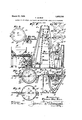
- Figure 1 is a broken sectional view of the appliance in operation constructed in accordance with this invention; many parts are shown diagrammatically on account of the reduced scale of the view.
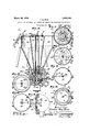
- Fig. 2 is an enlarged central section through the lower portion of the sand hopper on line m Figs. 8, 4 and 5.
- Fig. 3 is a plan view of a detached stationar slotted disk of one of the chargers.
- Fig. 4 is a cross section on line 00*, Figs. 1 and 2.
- Fig. 5 is a cross section on line m, Fig. 2.
- Fig. 6 is an enlarged central vertical section through the multiple hopper and associated parts.
- Fig. 7 is across section on line at, Fig. 6 showing a plan of the upper stationary s otted disk.
- Fig. 8 is a cross section on line 00 Fig. 6 showing a plan of the upper revolving charging disk.
- Fig. 9 is across section on line 02, Fig. 6 showing a top view ofthe stationary charge mixing disk.
- Fig. 10 is a cross section on line 04 Fig. 6 showing a plan of the lower slotted stationmy disk-
- Fig. 11 is a cross section on line Fig. 6 showing the lower revolving charge disk.
- Fig. 12 is a cross section on line w F1g. 6 showing a plan view of the lower statlonary discharging disk.
- Fig. 13 is an under side view of the mixing member shown in Fig. 9.
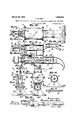
- Fi 20 is a sectional view of a nozzle on a re uced scale for use in filling a mold for a multiple wall.
- Fi 21 is a sectional view of a nozzle for formlng a double wall.
- Fig. 22 is a section on line Fig. 13.
- Figs. 23, 24 and 25 are diagrammatlc sectional details showing on a smaller scale the internal ways of the nozzle 49.
- the means for making and delivering .mixtures comprises a sizer apparatus 1 for first preparing the elements to be mixed and delivered and then discharging them under compressed air into separate compartments in a multiple receptacle hopper 2 that is provided with a charge measuring mixing and discharging mehcanism 3 that is connected to a final mixing and delivering appliance 4.
- the apparatus 1 which is adapted for treating the ingredients separately to reduce them to homogenous masses, comprises the separate sand, cement and color hoppers 5, 6,7, that are substantially alike in construction and operation and they are connected to the receptacle 2 by the delivery pipes 8 through which the material is delivered by compressed air from the hoppers to the compartments in the receptacle.
- the hoppers 5, 6, 7, have lids 9 that are provided with central gate valves 10 on the top of which are mounted the funnels that are adapted to receive the elements when in condition to be delivered to the mixer.
- a screen 12 mounted on a shaft 13 that is provided with a screw 14 in the bottom of the sand bin 15; and shaft 12 is driven by a motor 16, that is connected with a source of power not shown, but which is old and well understood.
- the sand from bin 15 is fed by the screw 14 onto the rotating screen 12 that permits the grains of desired size to fall into the funnel 11 and the residue is discharged outside the apparatus.
- valves 18 are closed and the valves 18 opened to permit compressed air to enter the chargers 19 and also conveyor pipes 8.
- Chargers 19 comprise cylindrical casings 20 secured to the bottoms of the hoppers 5, 6, 7, and these chargers are identical in con struction and operation except as to measuring the amount of material discharged; so
- a top stationary disk 21 that is provided with a concentric slot- 22 into which the sand of hopper 5 falls by gravity to fill the cylindrical charging receptacles 23 in the revolvable intermediate disk 24 that is supported under the disk 21 by a stationary bottom disk 25 that is threaded into the bottom of casing 20 and additionally secured therein by the set screws 26.
- the stationary disk 21 is provided with an air port 27 into which the discharge end of air pipe 28 is extended; and the air port 27 is in position to successively register with a discharge port 29 in the stationary disk 24 as the revolving disk 24 is rotated to bring its charging receptacles 23 into register with the ports 27 and 29. That is, as the disk 24 is revolved, its cylindrical charging receptacles 23 are successively moved under the air port 27 so that compressed air discharges from the pipe 28' out through the orifice or port 29, so that when the receptacles 23 are charged with sand, the material will be blown out through a pipe 30 that is fitted into the bottom end of port 29; and disk 24 is mounted on a shaft 56 driven by a motor 57.
- Pipe 30 has its lower end fitted into one arm of an inverted T pipe 31 that has its outer arms connected to the lower end of delivery pipe 8 and the other to the compressed air pipe 18 so that as the charges are blown from the receptacles 23 they are conveyed by compressed air through the delivery pipes 8 to the receptacle hopper 2.
- the air pressure for moving the mateials through the pipes 8 may be greater or less depending upon the force required to deliver them into the top of the multiple hop-
- the movable receptacle hopper may be provided with any number of hopper compartments; and as shown in Fig. 6 is provided with sand compartment 32, cement compartment 33, and color compartment 34, and the air pressure in these hopper compartments is regulated for each compartment, respectively, by pop valves 35 which .may be set to blow off at any desired pressure of air.
- the walls of these compartments are tapered inwardly and downwardly; and the lower ends of the walls are in air tight connection with a stationary slotted plate 36 that forms a floor for the compartments and which has concentric slots 37, 38, 39, registering with the bottoms of the respective hoppers 32, 33 and 34, so that material falls from said.
- hoppers by gravity and under whatever air pressure remains in said hoppers will fall through said slots and enter the charging chambers 39, 40 and 41 in a revolving charger plate 42 that is revolved by a shaft 43 driven by a motor 44.
- the chargers 39, 40 and 41 are of proportionate capacity corresponding to the proportions required of the different ingredients as sand, cement and color.
- the plate 42 rests upon the stationary plate 45 that is provided with holes 46, 47 and 48 corresponding in diameter with the several chargers 39, 40
- the centers of said holes 46, 47 48 are in a radial line from the center of the shaft 43 which revolves through the fixed plate 45 to revolve the plate 42.
- the orifices 46, 47, 48 in the plate 45 are connected to a mixing nozzle 49 by the passages 50, 51, 52; and compressed air is delivered through a passage 53 cut in the underside of plate 36 in position to discharge downward through orifices 39, 40, 41 in revolving 42 as they are successivelv moved into register with the holes 46, 47, 48 of plate 45 to discharge the material through the passages 50, 51, 52 that converge at the nozzle 49 and discharge therefrom into a slot in a plate 61.
- the sets of holes 39. 40, 41 in the charge plate 42 are arranged in radial alinement with each other, the larger holes forming an outside circle, the intermediate holes forming an intermediate circle and the smaller holes forming an inner circle.
- the slot 60 which is concentric to the shaft 43 and extends almost entirely around in said plate 61, and is adapted to deliver the mixed material from the nozzle 49 to revolving charger 62 having the charging holes 63 therethrough and resting upon the bottom piece 64 that closes the bottom of chamber 65 in which are mounted the plates 36, 42. 45, 61 and 64, and associated parts.
- Said bottom piece 64 supports the motor 44 and has a nipple 66 to which the hose 67 is attached to lead a dry mixture under air pressure from the charger holes 63 to the final mixing and delivering apparatus 4 shown in Figs. 1, 14, 15, 16, 17 and 18.
- This apparatus 4 comprises a small cylinder 69 to receive the dry material from the hose 67 and the same is provided internally with a shaft mounted revolving agitator 70 that is revolved by any suitable means as the sprocket Wheel 71, sprocket chain 72,.driven by sprocket Wheel 73 on the motor shaft 74.
- a shaft mounted revolving agitator 70 that is revolved by any suitable means as the sprocket Wheel 71, sprocket chain 72,.driven by sprocket Wheel 73 on the motor shaft 74.
- At the lower part of the cylinder 69 there is a longitudinal discharge slot 75 leading into a mixing conveyor barrel 76 in which the power shaft 74 revolves; the same being provided with the blades 77 and the discharging worm or screw 7 8. to discharge through the spider 79 to the nozzle 80.
- Said nozzle 80 may be of any desired form.
- the nozzle shown in Figs. 14 to 18 inclusive has a single rectangular opening arranged to discharge downward,
- the nozzle a in Fig. 20 is shown multiple as at b, c and 01. While in Fig. 21 the outlet 6 is annular.
- the apparatus 4 is portable as indicated by the handles 81 and its operation will be understood by the foregoing description.
- the motor driven parts will revolve at a predetermined speed, and the various dry ingredients and elements will be fed into the initial hoppers 5, 6, 7, there being a hopper for each of the ingredients and the material in comminuted condition as sand, powdered cement and powdered color will be delivered to the multiple hopper 2 and will pass therethrough to the charging apparatus at the bottom of said hopper; and under the pressure of the air through a r pipes 82 into the chargers 63, the hole 83 in the bottom 64 of the chamber 65.
- a Water pipe 84 is connected to a head 85 on the motor and of apparatus 4 from which is extended the parallel distributor pipes 86, 87 that are arranged between the cylinder 69 and 76 in position to discharge Water through orifices 88 downward and across the path of the mixture as it is discharged from cylinder 69 into the cylinder 76.
- the flow of water under pressure into the head 85 is regulated by a valve 89 in the pipe line 84. p
- the ways 50, 51, 52 in the mixing nozzle piece 49 converge toward each other and are proportionately reduced from rounded to elongated openings that converge in an enlarged single rectangular opening; and the ways are arranged to cross the path 0t one another as they discharge from nozzle 49 so as to thoroughly mix. 7
- the charger cavities 39, 40, 41 in the plate 42 may be of any desired. size and relative proportions and the proportions of the final mixture may be varied by substituting the plate 42 having cavities of one proportion for a plate having cavities of another proportion.
- the method set forth of producing and deliveringa quantitative mixture which consists of isolating predetermined charges of materials to be mixed, simultaneously spreading such materials under pressure through a common orifice, meanwhile spreading the charges to form parallel thin sheets and forcibly impacting said sheets against each other, thus thoroughly mixing the materials, separating the pro uce into charges and successively delivering such charges to a chamber, then adding water and mixing the product and discharging the mixture to the place Where it is to be used.
- the method set forth for making and delivering quantitative mixtures consisting of first treating the elements to reduce them to homogenous masses; then 'elevatingsaid elements to separate compartments in a container; then taking charges of each element of predetermined proportions and discharging them through ways or orifices that are inclined toward one another, so that in discharging, the elements will mix; then conveying the mixture to a container where it is subjected to additional mixing; then discharging the mass by gravity into a cylinder where it is moistened and kneaded into a semi-liquid mass; and then discl'iarging the semi-liquid mass from a nozzle.
- The. method of making and delivering quantitative mixtures consisting of first taking quantities of two or more dry ingrediants and treating them separately toreduce each to particles of homogenous sizes; then utilizing compressed air to deliver the sized ingredients to separate compartments in a receptacle; then utilizing compressed air and gravity to force the ingredients into charges of predetermined quantities; then utilizing compressed air to form a dry mixture of the ingredients by successively discharging the measured charges through a common orifice; then utilizing compressed air to deliver the dry mixture thus formed to a final mixer; then adding moisture to convert the dry into a wet mixture; and then forcingthe Wet mixture from the final mixer to a mold.
- the wet mixing and discharging appliance in combination with the means set forth for making and delivering quantitative mixtures comprising a barrel having an outlet thereto; a cylinder extending parallel with, and secured to, said barrel and adapted to receive a dry mixture, said cylinder having an elongated slot opening into said barrel through which the dry mixture falls ,by gravity; means for discharging water from opposite sides of the slot so that it will enter the mixture as it passes from said cylinder to said barrel; a shaft in said barrel; mixing blades on said shaft; a screw on said shaft adapted to force the wet mixture out of said barrel through the outlet thereof; and means for driving said shaft.
- the portable wet mixing and discharging appliance in combination with the means set forth for making and delivering quantitative mixtures comprising a barrel having an outlet thereto; a nozzle secured to the outlet of said barrel; a cylinder extend ing parallel with, and secured to, said barrel, said cylinder adapted to receive a dry mixture and having an elongated rectangular slot that opens from said cylinder into said barrel, through which the dry mixture falls by gravity; handles to said cylinder; an agitator in said cylinder; means for discharging water into the dry mixture as it passes from said cylinder into said barrel; a
- the wet mixing and discharging.appliance comprising a barrel; a cylinder adapted to receive a dry mixture, said cylinder having a discharge port opening into said barrel, pneumatic means for discharging the dry mixture from said cylinder into said barrel; an agitator in said cylinder; means for injecting water into the dry mixture as it discharges from said cylinder into said barrel; a power shaft in said barrel;- mixing blades on said shaft; and means for driving said shaft and agitator.
- the wet mixin ance comprising a arrel having an outlet and discharging applithereto; a cylinder extending parallel with, and secured to, said barrel and adapted to receive a dry mixture, said cylinder having an elongated slot opening into said barrel through which the .dry mixture falls by gravity; pneumatic means for discharging the dry material from said cylinder into said barrel; means for discharging water from opposite sides of the slot so that it will enter the mixture as it passes from said cylinder to said barrel; a shaft in said barrel; mixing blades on said shaft; a screw .on said shaft adapted to force the wet mixtureout of said barrel through the outlet thereof; and means for driving said shaft.
- the wet mixing and discharging appliance comprising a barrel having an outlet thereto; a nozzle secured to the outlet of said barrel; a cylinder extending parallel with,
- said barrel said cylinder adapted to receive a dry mixture and said cylinder having an elongated rectangular slot that opens therefrom into said barrel through whlch the dry mixture falls by grav-,
Landscapes
- Engineering & Computer Science (AREA)
- Mechanical Engineering (AREA)
- Chemical & Material Sciences (AREA)
- Dispersion Chemistry (AREA)
- Preparation Of Clay, And Manufacture Of Mixtures Containing Clay Or Cement (AREA)
Description
March 20, 1928.
T. M RAE METHOD OF AND MEANS FOR MAKING AND DELIVERING QUANTITATIVE MIXTURES I. 1 4/ 4 o ZMHJW 8 0w mw /n. a a S r. k Z 0 a3 w 46 I X ,t 0 m2 1% .6 w J, W n a 2 0 e F 4 W a e I r r 75$ I m .1 v 1m 9- .0 00 W 0 D W z n 1 M a ng d0 8 J 14v e (I C .m 7 4, z I a 0 m a ,rw y & y 0
March 20, 1928;
T. M RAE METHOD OF AND MEANS FOR MAKING AND DELIVERING QUANTITATIVE MIXTURES Filed June 25, 1923 Inventor. Thomas Mao Rae March 20, 1928.
'r. RAE
METHOD OF AND MEANS FQR MAKING AND DELIVERING QUANTITATIVE MIXTURES Filed Jun 25. 1923 g. If
c Rae. MW
3 Sheets-Sheet 3 Iuveni'oi'. Thomas Ma ,2 79
azfer 8] r fil'rfllre.
' b structing walls.
. Patented Mar. 20, 1928.
Parent ori ice.
THOMAS MACRAE, OF FLORENCE, ARIZONA.-
' METHOD OF AND MEANS FOR MAKING AND DELIVERING QUANTITATIVE MIXTURES.
Application filed June 25, 1923. Serial No. 647,616.
This invention relates to the production of concrete structures and of articles of various compositions and I shall illustrate the same herein, as applied in the art of con- An object is to provide in the building art a method and means whereby a better concrete body can be produced, and time and labor saved by mixing the solid ingredients such as cement and sand, gravel, and the like at a central station while dry, and then conducting it by pneumatic pressure through a tube to the place where it is to be disposed, and then adding the necessary water as the dry mixture is delivered from the tube and at the moment of delivery, to thoroughly incorporate the requisite water with the solids.
By this method it is possible to deliver an exactly proportioned plastic composition of the solids and the minimum amount of water thus avoiding any likelihood of making the mixture either too wet or too dry, or unevenly wet and dry.
An object of this invention is to accomplish the proportioning, mixing and pouring of the material with a minimized amount of manual labor, and also to avoid filling the air with the dust common to such labor. To that end I provide co-acting power actuated 3" apparatus that proportions, mixes and pours the composition of matter and have provided appliances constructed to confine the dust.
An object of the invention is to provide means for producing a mixture of nearly exact proportions; and to that end, I provide automatic measuring means that successively carries charges of the several ingredients in right proportions to a common opening through which the ingredients are discharged by air pressure.
A An object of the invention is to provide a very simple method of compounding materials that is easily employed by unskilled labor; and to provide means in connection therewith, whereby the operation of constructing or repairing concrete walls, floors and other bodies, or of applying plastic or concrete coatings to walls and the like can be accomplished by unskilled labor.
An object of the invention is to make provision whereby cheap, strong and durable structures can be'made at nominal cost of material and. la r.
Features of the invention are shown in the construction, combmation and arrangement of co-acting parts to secure the objects above referred to.
This novel method comprises the'mechanical measurement and isolation of charges of dry'material to be mixed, and a penumatic removal of such charges from the place of measurement in predetermined quantities to a common passage, where they are mixed. Pneumatic transportation of the mixed dry materials confined from the external air in a conduit as a pipe and hose and then discharging the mixed dry materials through an outlet with a final and coincident thorough agitating and mixing of the solids with the requisite water to form the concrete plastic mass as it is put in place in the body to be made.
Other objects, advantages and featuresof invention may appear from the accompanying drawings, the subjoined detail description and the appended claims.
The accompanying drawings illustrate the invention.
Figure 1 is a broken sectional view of the appliance in operation constructed in accordance with this invention; many parts are shown diagrammatically on account of the reduced scale of the view.
Fig. 2 is an enlarged central section through the lower portion of the sand hopper on line m Figs. 8, 4 and 5.
Fig. 3 is a plan view of a detached stationar slotted disk of one of the chargers.
Fig. 4 is a cross section on line 00*, Figs. 1 and 2.
Fig. 5 is a cross section on line m, Fig. 2.
Fig. 6 is an enlarged central vertical section through the multiple hopper and associated parts.
Fig. 7 is across section on line at, Fig. 6 showing a plan of the upper stationary s otted disk.
Fig. 8 is a cross section on line 00 Fig. 6 showing a plan of the upper revolving charging disk.
Fig. 9 is across section on line 02, Fig. 6 showing a top view ofthe stationary charge mixing disk.
Fig. 10 is a cross section on line 04 Fig. 6 showing a plan of the lower slotted stationmy disk- Fig. 11 is a cross section on line Fig. 6 showing the lower revolving charge disk. Fig. 12 is a cross section on line w F1g. 6 showing a plan view of the lower statlonary discharging disk.
' Fig. 13 is an under side view of the mixing member shown in Fig. 9.
, showing the rectangular discharge openlng of the nozzle for use in filling a mold for a single wall.
Fig. 22 is a section on line Fig. 13.
Figs. 23, 24 and 25 are diagrammatlc sectional details showing on a smaller scale the internal ways of the nozzle 49.
The means for making and delivering .mixtures comprises a sizer apparatus 1 for first preparing the elements to be mixed and delivered and then discharging them under compressed air into separate compartments in a multiple receptacle hopper 2 that is provided with a charge measuring mixing and discharging mehcanism 3 that is connected to a final mixing and delivering appliance 4.
The apparatus 1, which is adapted for treating the ingredients separately to reduce them to homogenous masses, comprises the separate sand, cement and color hoppers 5, 6,7, that are substantially alike in construction and operation and they are connected to the receptacle 2 by the delivery pipes 8 through which the material is delivered by compressed air from the hoppers to the compartments in the receptacle. The hoppers 5, 6, 7, have lids 9 that are provided with central gate valves 10 on the top of which are mounted the funnels that are adapted to receive the elements when in condition to be delivered to the mixer.
Mounted above the funnel 11 of said hopper 5 is a screen 12 mounted on a shaft 13 that is provided with a screw 14 in the bottom of the sand bin 15; and shaft 12 is driven by a motor 16, that is connected with a source of power not shown, but which is old and well understood.
The sand from bin 15 is fed by the screw 14 onto the rotating screen 12 that permits the grains of desired size to fall into the funnel 11 and the residue is discharged outside the apparatus.
are closed and the valves 18 opened to permit compressed air to enter the chargers 19 and also conveyor pipes 8.
Chargers 19 comprise cylindrical casings 20 secured to the bottoms of the hoppers 5, 6, 7, and these chargers are identical in con struction and operation except as to measuring the amount of material discharged; so
that a description of the sand charger will also disclose the construction and operation of the cement and coloring chargers.
In the casing 20, is secured a top stationary disk 21 that is provided with a concentric slot- 22 into which the sand of hopper 5 falls by gravity to fill the cylindrical charging receptacles 23 in the revolvable intermediate disk 24 that is supported under the disk 21 by a stationary bottom disk 25 that is threaded into the bottom of casing 20 and additionally secured therein by the set screws 26.
The stationary disk 21 is provided with an air port 27 into which the discharge end of air pipe 28 is extended; and the air port 27 is in position to successively register with a discharge port 29 in the stationary disk 24 as the revolving disk 24 is rotated to bring its charging receptacles 23 into register with the ports 27 and 29. That is, as the disk 24 is revolved, its cylindrical charging receptacles 23 are successively moved under the air port 27 so that compressed air discharges from the pipe 28' out through the orifice or port 29, so that when the receptacles 23 are charged with sand, the material will be blown out through a pipe 30 that is fitted into the bottom end of port 29; and disk 24 is mounted on a shaft 56 driven by a motor 57.
The air pressure for moving the mateials through the pipes 8 may be greater or less depending upon the force required to deliver them into the top of the multiple hop- The movable receptacle hopper may be provided with any number of hopper compartments; and as shown in Fig. 6 is provided with sand compartment 32, cement compartment 33, and color compartment 34, and the air pressure in these hopper compartments is regulated for each compartment, respectively, by pop valves 35 which .may be set to blow off at any desired pressure of air.
The walls of these compartments are tapered inwardly and downwardly; and the lower ends of the walls are in air tight connection with a stationary slotted plate 36 that forms a floor for the compartments and which has concentric slots 37, 38, 39, registering with the bottoms of the respective hoppers 32, 33 and 34, so that material falls from said. hoppers by gravity and under whatever air pressure remains in said hoppers will fall through said slots and enter the charging chambers 39, 40 and 41 in a revolving charger plate 42 that is revolved by a shaft 43 driven by a motor 44. The chargers 39, 40 and 41 are of proportionate capacity corresponding to the proportions required of the different ingredients as sand, cement and color. The plate 42 rests upon the stationary plate 45 that is provided with holes 46, 47 and 48 corresponding in diameter with the several chargers 39, 40
and 41.
The centers of said holes 46, 47 48 are in a radial line from the center of the shaft 43 which revolves through the fixed plate 45 to revolve the plate 42. The orifices 46, 47, 48 in the plate 45 are connected to a mixing nozzle 49 by the passages 50, 51, 52; and compressed air is delivered through a passage 53 cut in the underside of plate 36 in position to discharge downward through orifices 39, 40, 41 in revolving 42 as they are successivelv moved into register with the holes 46, 47, 48 of plate 45 to discharge the material through the passages 50, 51, 52 that converge at the nozzle 49 and discharge therefrom into a slot in a plate 61.
The sets of holes 39. 40, 41 in the charge plate 42 are arranged in radial alinement with each other, the larger holes forming an outside circle, the intermediate holes forming an intermediate circle and the smaller holes forming an inner circle.
The slot 60 which is concentric to the shaft 43 and extends almost entirely around in said plate 61, and is adapted to deliver the mixed material from the nozzle 49 to revolving charger 62 having the charging holes 63 therethrough and resting upon the bottom piece 64 that closes the bottom of chamber 65 in which are mounted the plates 36, 42. 45, 61 and 64, and associated parts.
Said bottom piece 64 supports the motor 44 and has a nipple 66 to which the hose 67 is attached to lead a dry mixture under air pressure from the charger holes 63 to the final mixing and delivering apparatus 4 shown in Figs. 1, 14, 15, 16, 17 and 18.
This apparatus 4 comprises a small cylinder 69 to receive the dry material from the hose 67 and the same is provided internally with a shaft mounted revolving agitator 70 that is revolved by any suitable means as the sprocket Wheel 71, sprocket chain 72,.driven by sprocket Wheel 73 on the motor shaft 74. At the lower part of the cylinder 69 there is a longitudinal discharge slot 75 leading into a mixing conveyor barrel 76 in which the power shaft 74 revolves; the same being provided with the blades 77 and the discharging worm or screw 7 8. to discharge through the spider 79 to the nozzle 80.
Said nozzle 80 may be of any desired form. The nozzle shown in Figs. 14 to 18 inclusive has a single rectangular opening arranged to discharge downward, The nozzle a in Fig. 20 is shown multiple as at b, c and 01. While in Fig. 21 the outlet 6 is annular.
The apparatus 4 is portable as indicated by the handles 81 and its operation will be understood by the foregoing description.
In practice the motor driven parts will revolve at a predetermined speed, and the various dry ingredients and elements will be fed into the initial hoppers 5, 6, 7, there being a hopper for each of the ingredients and the material in comminuted condition as sand, powdered cement and powdered color will be delivered to the multiple hopper 2 and will pass therethrough to the charging apparatus at the bottom of said hopper; and under the pressure of the air through a r pipes 82 into the chargers 63, the hole 83 in the bottom 64 of the chamber 65.
A Water pipe 84 is connected to a head 85 on the motor and of apparatus 4 from which is extended the parallel distributor pipes 86, 87 that are arranged between the cylinder 69 and 76 in position to discharge Water through orifices 88 downward and across the path of the mixture as it is discharged from cylinder 69 into the cylinder 76.
The flow of water under pressure into the head 85 is regulated by a valve 89 in the pipe line 84. p
The ways 50, 51, 52 in the mixing nozzle piece 49 converge toward each other and are proportionately reduced from rounded to elongated openings that converge in an enlarged single rectangular opening; and the ways are arranged to cross the path 0t one another as they discharge from nozzle 49 so as to thoroughly mix. 7
The charger cavities 39, 40, 41 in the plate 42 may be of any desired. size and relative proportions and the proportions of the final mixture may be varied by substituting the plate 42 having cavities of one proportion for a plate having cavities of another proportion.
I claim:
1. The method set forth of producing and deliveringa quantitative mixture which consists of isolating predetermined charges of materials to be mixed, simultaneously spreading such materials under pressure through a common orifice, meanwhile spreading the charges to form parallel thin sheets and forcibly impacting said sheets against each other, thus thoroughly mixing the materials, separating the pro uce into charges and successively delivering such charges to a chamber, then adding water and mixing the product and discharging the mixture to the place Where it is to be used.
2. The method set forth for making and delivering quantitative mixtures consisting of first treating the elements to reduce them to homogenous masses; then 'elevatingsaid elements to separate compartments in a container; then taking charges of each element of predetermined proportions and discharging them through ways or orifices that are inclined toward one another, so that in discharging, the elements will mix; then conveying the mixture to a container where it is subjected to additional mixing; then discharging the mass by gravity into a cylinder where it is moistened and kneaded into a semi-liquid mass; and then discl'iarging the semi-liquid mass from a nozzle.
3. The method of making and delivering quantitative mixtures consisting of first taking quantities of two or more dry substances and treating them separately to reduce each guantity to particles ofuniform sizes; then ividing each of the reduced substances into charges of predetermined quantities; then successively combining a charge of each substance with charges of the other substances to form a di -y mixture; then using air under pressure to deliver the dry mixture toa final mixture; and then adding moisture to convert the dry into a wet mixture.
4. The method of making and delivering quantitative mixtures consisting of first takmg quantities of two or more dry ingredients and treating them separately to reduce each to articles of uniform sizes; then divide eaci quantity into charges of predetermined sizes; then using air under pressure to successively mingle a charge of each substance with the other substances to form a dry mixture; then again using compressed air to deliver the dry mixture to a final mixer; and then adding a moisture to convert the dry into wet mixture.
5. The. method of making and delivering quantitative mixtures consisting of first taking quantities of two or more dry ingrediants and treating them separately toreduce each to particles of homogenous sizes; then utilizing compressed air to deliver the sized ingredients to separate compartments in a receptacle; then utilizing compressed air and gravity to force the ingredients into charges of predetermined quantities; then utilizing compressed air to form a dry mixture of the ingredients by successively discharging the measured charges through a common orifice; then utilizing compressed air to deliver the dry mixture thus formed to a final mixer; then adding moisture to convert the dry into a wet mixture; and then forcingthe Wet mixture from the final mixer to a mold.
6. The wet mixing and discharging appliance in combination with the means set forth for making and delivering quantitative mixtures comprising a barrel having an outlet thereto; a cylinder extending parallel with, and secured to, said barrel and adapted to receive a dry mixture, said cylinder having an elongated slot opening into said barrel through which the dry mixture falls ,by gravity; means for discharging water from opposite sides of the slot so that it will enter the mixture as it passes from said cylinder to said barrel; a shaft in said barrel; mixing blades on said shaft; a screw on said shaft adapted to force the wet mixture out of said barrel through the outlet thereof; and means for driving said shaft.
' 7. The portable wet mixing and discharging appliance in combination with the means set forth for making and delivering quantitative mixtures comprising a barrel having an outlet thereto; a nozzle secured to the outlet of said barrel; a cylinder extend ing parallel with, and secured to, said barrel, said cylinder adapted to receive a dry mixture and having an elongated rectangular slot that opens from said cylinder into said barrel, through which the dry mixture falls by gravity; handles to said cylinder; an agitator in said cylinder; means for discharging water into the dry mixture as it passes from said cylinder into said barrel; a
shaft in said barrel; mixing blades on said shaft; a screw on said shaft that is adapted to force the wet mixture from said barrel and through said nozzle; a driving connection between said shaft and agitator; and a motor for driving said shaft.
8.=The wet mixing and discharging.appliance comprising a barrel; a cylinder adapted to receive a dry mixture, said cylinder having a discharge port opening into said barrel, pneumatic means for discharging the dry mixture from said cylinder into said barrel; an agitator in said cylinder; means for injecting water into the dry mixture as it discharges from said cylinder into said barrel; a power shaft in said barrel;- mixing blades on said shaft; and means for driving said shaft and agitator.
9. The wet mixin ance comprising a arrel having an outlet and discharging applithereto; a cylinder extending parallel with, and secured to, said barrel and adapted to receive a dry mixture, said cylinder having an elongated slot opening into said barrel through which the .dry mixture falls by gravity; pneumatic means for discharging the dry material from said cylinder into said barrel; means for discharging water from opposite sides of the slot so that it will enter the mixture as it passes from said cylinder to said barrel; a shaft in said barrel; mixing blades on said shaft; a screw .on said shaft adapted to force the wet mixtureout of said barrel through the outlet thereof; and means for driving said shaft.
10. The wet mixing and discharging appliance comprising a barrel having an outlet thereto; a nozzle secured to the outlet of said barrel; a cylinder extending parallel with,
and secured to, said barrel, said cylinder adapted to receive a dry mixture and said cylinder having an elongated rectangular slot that opens therefrom into said barrel through whlch the dry mixture falls by grav-,
ity; pneumatic means for discharging the dry material from said cylinder into said barrel; an agitator in said cylinder; means for discharging water into the dry mixture as it passes from said cylinder into said barrel; a shaft in said barrel; mixing blades on said shaft; a screw on said shaft that is adapted to force the wet mixture from said barrel and through said nozzle; and a 'motor for driving said agitator and shaft.
In testimony whereof, I have hereunto set my hand at Los Angeles, California, this 5th day of May, 1923-..
' THOMAS MAGRAE.
Priority Applications (1)
| Application Number | Priority Date | Filing Date | Title |
|---|---|---|---|
| US647616A US1663206A (en) | 1923-06-25 | 1923-06-25 | Method of and means for making and delivering quantitative mixtures |
Applications Claiming Priority (1)
| Application Number | Priority Date | Filing Date | Title |
|---|---|---|---|
| US647616A US1663206A (en) | 1923-06-25 | 1923-06-25 | Method of and means for making and delivering quantitative mixtures |
Publications (1)
| Publication Number | Publication Date |
|---|---|
| US1663206A true US1663206A (en) | 1928-03-20 |
Family
ID=24597668
Family Applications (1)
| Application Number | Title | Priority Date | Filing Date |
|---|---|---|---|
| US647616A Expired - Lifetime US1663206A (en) | 1923-06-25 | 1923-06-25 | Method of and means for making and delivering quantitative mixtures |
Country Status (1)
| Country | Link |
|---|---|
| US (1) | US1663206A (en) |
Cited By (13)
| Publication number | Priority date | Publication date | Assignee | Title |
|---|---|---|---|---|
| US2615693A (en) * | 1947-04-15 | 1952-10-28 | Basic Refractories Inc | Apparatus for feeding ground materials |
| US3034732A (en) * | 1957-07-18 | 1962-05-15 | Archilithics Co | Monolithic wall forming apparatus |
| US3331098A (en) * | 1963-12-09 | 1967-07-18 | Sr John W Macpherson | Apparatus and method for manufacturing flowers and like articles from plastic material |
| US3339898A (en) * | 1965-02-17 | 1967-09-05 | Irl Daffin Associates | Mixing method and mixing trough construction |
| US3672646A (en) * | 1971-04-15 | 1972-06-27 | Detroit Tool & Eng Co | Pneumatic cement gun machine |
| US3705710A (en) * | 1971-06-07 | 1972-12-12 | Tetradyne Corp | Solids feeder system |
| US3779519A (en) * | 1971-06-07 | 1973-12-18 | Tetradyne Corp | Concrete placement |
| FR2369397A1 (en) * | 1976-10-28 | 1978-05-26 | Beton Spritz Masch Gmbh & Co | COMPRESSED AIR MACHINE FOR THROWING CONCRETE, MORTAR OR SIMILAR AGGLOMERATE |
| DE2931505A1 (en) * | 1978-08-03 | 1980-02-14 | Ebenseer Betonwerke Gmbh | Concrete delivery machine into shuttering - has device metering material affecting concrete quality near trough |
| DE3119811A1 (en) * | 1981-05-19 | 1982-12-16 | Georg Schöndorfer GmbH & Co KG, 8230 Bad Reichenhall | DEVICE FOR MIXING AND SPRAYING WET CONCRETE |
| FR2644491A1 (en) * | 1989-03-15 | 1990-09-21 | Regicentre Sarl | Method for preparing and beating up fine mortars and slurry for filling underground holes |
| EP0592793A1 (en) * | 1992-10-15 | 1994-04-20 | PFT Putz- und Fördertechnik GmbH & Co. KG | Method and apparatus for applying mortar or concrete through spraying |
| US5433519A (en) * | 1993-08-26 | 1995-07-18 | Pft Putz Und Fordertechnik Gmbh | Method and apparatus for the application of mortar or concrete by spraying |
-
1923
- 1923-06-25 US US647616A patent/US1663206A/en not_active Expired - Lifetime
Cited By (13)
| Publication number | Priority date | Publication date | Assignee | Title |
|---|---|---|---|---|
| US2615693A (en) * | 1947-04-15 | 1952-10-28 | Basic Refractories Inc | Apparatus for feeding ground materials |
| US3034732A (en) * | 1957-07-18 | 1962-05-15 | Archilithics Co | Monolithic wall forming apparatus |
| US3331098A (en) * | 1963-12-09 | 1967-07-18 | Sr John W Macpherson | Apparatus and method for manufacturing flowers and like articles from plastic material |
| US3339898A (en) * | 1965-02-17 | 1967-09-05 | Irl Daffin Associates | Mixing method and mixing trough construction |
| US3672646A (en) * | 1971-04-15 | 1972-06-27 | Detroit Tool & Eng Co | Pneumatic cement gun machine |
| US3705710A (en) * | 1971-06-07 | 1972-12-12 | Tetradyne Corp | Solids feeder system |
| US3779519A (en) * | 1971-06-07 | 1973-12-18 | Tetradyne Corp | Concrete placement |
| FR2369397A1 (en) * | 1976-10-28 | 1978-05-26 | Beton Spritz Masch Gmbh & Co | COMPRESSED AIR MACHINE FOR THROWING CONCRETE, MORTAR OR SIMILAR AGGLOMERATE |
| DE2931505A1 (en) * | 1978-08-03 | 1980-02-14 | Ebenseer Betonwerke Gmbh | Concrete delivery machine into shuttering - has device metering material affecting concrete quality near trough |
| DE3119811A1 (en) * | 1981-05-19 | 1982-12-16 | Georg Schöndorfer GmbH & Co KG, 8230 Bad Reichenhall | DEVICE FOR MIXING AND SPRAYING WET CONCRETE |
| FR2644491A1 (en) * | 1989-03-15 | 1990-09-21 | Regicentre Sarl | Method for preparing and beating up fine mortars and slurry for filling underground holes |
| EP0592793A1 (en) * | 1992-10-15 | 1994-04-20 | PFT Putz- und Fördertechnik GmbH & Co. KG | Method and apparatus for applying mortar or concrete through spraying |
| US5433519A (en) * | 1993-08-26 | 1995-07-18 | Pft Putz Und Fordertechnik Gmbh | Method and apparatus for the application of mortar or concrete by spraying |
Similar Documents
| Publication | Publication Date | Title |
|---|---|---|
| US1663206A (en) | Method of and means for making and delivering quantitative mixtures | |
| US1953091A (en) | Concrete conveying and mixing machine | |
| JP2509553B2 (en) | Granular compounding equipment | |
| US20050219941A1 (en) | Concrete batching facility and method | |
| US20150103614A1 (en) | Apparatus and method for a concrete plant | |
| CN109999713A (en) | A kind of automation charging device | |
| US4865457A (en) | Concrete batcher with segmented entry of mixing ingredients | |
| US2104191A (en) | Mixing apparatus | |
| US722782A (en) | Apparatus for making concrete. | |
| US2079565A (en) | Machine for mixing plastic material | |
| US1758200A (en) | Wet mixing method and apparatus | |
| US633313A (en) | Apparatus for making concrete. | |
| US3131911A (en) | Feed blender | |
| CN207174934U (en) | Mix conveying device | |
| USRE20440E (en) | Concrete conveying and mixing machine | |
| KR100875501B1 (en) | Material Mixing / Supply Unit | |
| CN108789854A (en) | A kind of full-automatic premixing dry-mixed mortar preparation mixing arrangement | |
| RU2031787C1 (en) | Installation for preparation of multicomponent mixture | |
| US3129779A (en) | Weighing and discharge apparatus | |
| US4133490A (en) | Machine for making cellulose insulation | |
| GB218026A (en) | Improvements in or relating to apparatus for mixing finely divided or powdered substances | |
| US1097084A (en) | Method of mixing concrete and the like. | |
| US533488A (en) | Machine for manufacturing artificial fuel | |
| CN218221928U (en) | Accurate batching structure of cement raw material homogenization storehouse | |
| CN214636044U (en) | Automatic refractory material batching system |