US1663198A - Posting tray - Google Patents
Posting tray Download PDFInfo
- Publication number
- US1663198A US1663198A US751722A US75172224A US1663198A US 1663198 A US1663198 A US 1663198A US 751722 A US751722 A US 751722A US 75172224 A US75172224 A US 75172224A US 1663198 A US1663198 A US 1663198A
- Authority
- US
- United States
- Prior art keywords
- plate
- sheets
- base
- tray
- posting
- Prior art date
- Legal status (The legal status is an assumption and is not a legal conclusion. Google has not performed a legal analysis and makes no representation as to the accuracy of the status listed.)
- Expired - Lifetime
Links
- 230000008093 supporting effect Effects 0.000 description 3
- 210000002105 tongue Anatomy 0.000 description 2
- CZRCFAOMWRAFIC-UHFFFAOYSA-N 5-(tetradecyloxy)-2-furoic acid Chemical compound CCCCCCCCCCCCCCOC1=CC=C(C(O)=O)O1 CZRCFAOMWRAFIC-UHFFFAOYSA-N 0.000 description 1
- 230000015572 biosynthetic process Effects 0.000 description 1
- 238000006073 displacement reaction Methods 0.000 description 1
- 230000000694 effects Effects 0.000 description 1
- 239000000463 material Substances 0.000 description 1
- 239000002184 metal Substances 0.000 description 1
- 230000000717 retained effect Effects 0.000 description 1
Images
Classifications
-
- B—PERFORMING OPERATIONS; TRANSPORTING
- B42—BOOKBINDING; ALBUMS; FILES; SPECIAL PRINTED MATTER
- B42F—SHEETS TEMPORARILY ATTACHED TOGETHER; FILING APPLIANCES; FILE CARDS; INDEXING
- B42F17/00—Card-filing arrangements, e.g. card indexes or catalogues or filing cabinets
- B42F17/02—Card-filing arrangements, e.g. card indexes or catalogues or filing cabinets in which the cards are stored substantially at right angles to the bottom of their containers
-
- Y—GENERAL TAGGING OF NEW TECHNOLOGICAL DEVELOPMENTS; GENERAL TAGGING OF CROSS-SECTIONAL TECHNOLOGIES SPANNING OVER SEVERAL SECTIONS OF THE IPC; TECHNICAL SUBJECTS COVERED BY FORMER USPC CROSS-REFERENCE ART COLLECTIONS [XRACs] AND DIGESTS
- Y10—TECHNICAL SUBJECTS COVERED BY FORMER USPC
- Y10T—TECHNICAL SUBJECTS COVERED BY FORMER US CLASSIFICATION
- Y10T29/00—Metal working
- Y10T29/53—Means to assemble or disassemble
- Y10T29/53674—Loose-leaf sheet binder
Definitions
- abaselB formedroffsheet metal on other suitable material and. includinga .bottom supported on legs 16 and. provided! with an rip-turnedflange 17 to which are:seeurechsidos 18; a front 19 and a top 20 having.- adepending portion. 21 constituting the back wall. of. the baseand which is. securedJtothe flange 17..
- the top.20 constiledger sheets are adapted to be supported; andthis top is. provided at its forward edge with an upstanding lip that co-operates with another lip formed on the front wall 19110 provide a stationary plate 22 which is in-' clined as shown.
- the top 20 is formed cen: trally with a longitudinally extending slot 20* in which a, standard 23 is inounted'toj slide longitudinally with respect to the floor 20.
- The'lower end of the standard 23 is formed with a sleeve 24 which is interiorly threaded to receive and engage a screw threaded shaft 25 arranged beneath the floor 20 and hav'ing'its rear end rotatablyand 5 detachably associated with 'asuitable' sup 7 port 26;
- the forward end of the screw shaft 25 is rotatably mounted in a bearing plate and this plate is formed with 'airopening which registers with an openingin the front 79 wall?
- Rivet'ed. or otherwise secured to the standard 23 is a plate 31, the standard and plate of the slot 20 in serving. to maintain the plate 31 in rigid upstandard 23 and'the right position. k
- the remainder of the sheet clamping device includes-a. stationary plate 22 and a" movable.plate34', the latter being formed at its lower edge withtongues'35 ( Figure'5) which are remov'ably fitted in transverse slots 361fOrmed in the floor 20 and at points adjacent.
- the stationary plate 22 in order that the latter may function to support the movable plate intheinclined position shown in Figure 1. Inthis position of the plate 24 it is disposed diverging relation with respect y to the plate 31.
- the back member including the plate 31 and the standard '23 can be adjusted longitudinally of the floor 20 by a rotation ofthe shaft 25, the sleeve 24 being thus actuated through the threads so as to be moved longitudinally of the shaft and to thereby effect a corresponding adjustment of the back member of-the clamping device.
- the stacked sheets illustrated can be readily separated to permit the withdrawal of the sheets for posting purposes. It will beunderstood that the entire stack of sheets is normally supported in inclined position by the back member of the clamping device he moved singly or in groups to the movable plate34 and retained in such position by virtue of the inclination of such plate. 2
- the back member can. be advanced by manipulation of the shaft to the position shown in Figure 1, wherein the stack of sheets is forced into clamping engagement with respect to the stationary plate 22, and the sheets thus held at their lower marginal edges to permit flexing. of the same as illustrated. It will be understood that in this use of the posting tray the movable plate 34 is removed from the When the ledger sheets are not in relation as illustrated in Figure 4 by interposing the movable plate 34 between the stationary plate 22 and the stack of sheets so that by advancing the back member in the direction of the stationary plate, the sheets will be firmly clamped between the plates 31 and 34.
- the Side walls 18 are formed with hand openings 37 which allow the gripping of the base, as will be understood. It is to be particularly noted that the side walls 18 are extended above the floor 20 so that they co-operate with the clamping device in preventing lateral dis: placement of the sheets from the stack.
- a posting tray comprising a' base, a
- V back plate in inclined position onthe base to support stacked sheets approximately verp a front platesupported on I tically thereon, and removable from the base, a stationary plate on the base, and means for moving the back plate on the base toward or away from the front and stationary plates.
- a posting tray comprising'a base, a back plate, a front stationary plate on the base, disposed in parallelism tothe back plate, and means for moving the "back plate toward or away from the front plate, whereby the back plate can be moved toward the front plateto'cause the two to cooperate in clamping sheets therebetween and in such manner that the sheets can 'be' bent outwardly for reference purposes;
- a posting tray “comprising aj base, a back member on the base a ainst' which stacked sheets are adapted to%) a front mem er including a stationary portion fixed to the base and a movable portion movable on the base to occupy one position in which it is supported in inclined position by the stationary portion and in divergent relation to'the back member and another position in which it is parallel to and between the back member and the stationary portion, and means for moving the back member on the base to cause the stacked sheets to be clam ed between-the back and front members w en the said movable portion is in the secondmentioned position, and to support the sheets in divergent relation when the movable portion is in the first-mentioned position.
- a posting tray comprising a base having a floor formed with longitudinal and transverse slots, a screw threaded shaft journaled in the base below the floor, a sleeve threaded on the shaft, a standard secured to the sleeve and projecting through the longitudinal slots of the floor, a sheet supporting member connected to the standard, a stationary element at one end of the floor, a movable member associated with the sheet sup porting member and being formed with tongues removably fitted in the transverse slots of the floor, and means comprising a crank detachably associated with the shaft for operating the same.
- a posting tray comprising a base, a back plate in inclined position on the base to supportistacked sheets approximately vertically thereon, a front plate supported on the base to occupy one position in whichit is parallel to the back plate and another position in which it is. divergent with respect to f the back plate, and means for moving the the first member on the base toward or away from the other members.
Landscapes
- Pile Receivers (AREA)
Description
C. B. HARRISON March 20, 1928.
POSTING TRAY Filed NOV. 24. 1924 2 Sheets-Sheet' 1 Qwueystoz (EC/L Balk/W50 35 i Z0 Z4 March 20, 1928. I 1,663,198
c. B. HARRISON I Pos'rme mu Filed Nov. 24. 1924 2 Sheets-Sheet z 65 04, 5. Haze/5w Patented Mar. 20, 1928., e
airs star's on cinrnlzrmnn HARRISON, or HOLLYWOO 'cALIFO NIA, assrenoai BY mnsnnies sIGNM-Entrs; To'BANKERS-EQUIPMENT COMPANY-,0}? nosanennns, cameos/MIA,
A CORPORATION or CALIFORNIA.
POSTING TRAY.
Application filed November24, 19245 Serial lfi'o. 751,722.
tieal-..position tofa cilitate reference. thereto and posting, thereon of records. ofrany description' Itis a purpose of my invention toprovide a.posting, tray of. the above described cliaraeter having ledger sheet supporting. memhere which are adjustable and separable one 'to;tlieother whereby the-sheets can be re moved[. for. posting,. separated. withoutre 1noVal-:for reference purposes, and. securely clamped together. when the tray is. not. in use; oh-1135 affording aprotectmg means and support for thesheets. I p
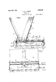
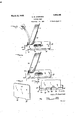
I; will describe 1 only one, form of. posting tray emhodying my;invention.1and.will then point .out the: novel features thereof in claims. v p j In the accoinpanyingdrawings- Figure lfis'oaview showing in vertical longitudinal section one form of posting tray embodying invention Figure.2..is avertical sectional view taken on. the line 2. 2 of Figure. 1;. v 1 igures3. andi 4' are views showing in side elevation andlpartly in section twoposit-ions and uses .oflthe sheet vclampingfmeans 30 "embodied in. the. posting tray shown in the preceding views Figureo is a fragmentary sectional View takenon the line 5-5 of Figure'l;
Figure 6.is*a detail. perspective View of the movable. portion. of one of the-sheet clamping;- members embodied. in the tray shownin the preceding. views. Y Similar.reference'characters refer to similar. partsin each of theseveral views of the drawing, 1
Referring specificallyto the drawings, andparticularlytoFigui-es 1 and 2, I have here shown abaselB formedroffsheet metal on other suitable material: and. includinga .bottom supported on legs 16 and. provided! with an rip-turnedflange 17 to which are:seeurechsidos 18; a front 19 and a top 20 having.- adepending portion. 21 constituting the back wall. of. the baseand which is. securedJtothe flange 17.. The top.20 constiledger sheets are adapted to be supported; andthis top is. provided at its forward edge with an upstanding lip that co-operates with another lip formed on the front wall 19110 provide a stationary plate 22 which is in-' clined as shown. The top 20 is formed cen: trally with a longitudinally extending slot 20* in which a, standard 23 is inounted'toj slide longitudinally with respect to the floor 20.. The'lower end of the standard 23 is formed with a sleeve 24 which is interiorly threaded to receive and engage a screw threaded shaft 25 arranged beneath the floor 20 and hav'ing'its rear end rotatablyand 5 detachably associated with 'asuitable' sup 7 port 26; The forward end of the screw shaft 25 is rotatably mounted in a bearing plate and this plate is formed with 'airopening which registers with an openingin the front 79 wall? 19 of the base so as to perinita socket 280f a'crank29 to be appliedto; the shaft toreceive a head'30 on the forward end of the shaftfwhereby the shaft can bemanually rotated by thecrank. The. crank.- can be detached from the shaft when'not in use.
Rivet'ed. or otherwise secured to the standard 23 is a plate 31, the standard and plate of the slot 20 in serving. to maintain the plate 31 in rigid upstandard 23 and'the right position. k
The remainder of the sheet clamping device includes-a. stationary plate 22 and a" movable.plate34', the latter being formed at its lower edge withtongues'35 (Figure'5) which are remov'ably fitted in transverse slots 361fOrmed in the floor 20 and at points adjacent. the stationary plate 22 in order that the latter may function to support the movable plate intheinclined position shown in Figure 1. Inthis position of the plate 24 it is disposed diverging relation with respect y to the plate 31. The plate 34 is also capable and that they may sheets'of the stack, and at tray; use, they may be firmly clamped in stacked =tray from place to place,
of occupying another position in which it is parallel to the plate 31,as clearly shown in Figure 4. In this position of the plate the tongues 35 are removed from the slots 36, and the plate lies contiguous to the stationary 7 plate 22 so that the two co-act with the back 7 plate 31 infirmly clamping the ledger sheets in stacked formation.
In operation, the back member including the plate 31 and the standard '23 can be adjusted longitudinally of the floor 20 by a rotation ofthe shaft 25, the sleeve 24 being thus actuated through the threads so as to be moved longitudinally of the shaft and to thereby effect a corresponding adjustment of the back member of-the clamping device. \Vith the back member in the position shown in Figure 1, and the movable plate 34 occupyinga diverging position with respectto the back member, it will be clear that the stacked sheets illustrated can be readily separated to permit the withdrawal of the sheets for posting purposes. It will beunderstood that the entire stack of sheets is normally supported in inclined position by the back member of the clamping device he moved singly or in groups to the movable plate34 and retained in such position by virtue of the inclination of such plate. 2
When it is desired to refer to any of the the same time to secure the sheets against removal or disarrangement, the back member can. be advanced by manipulation of the shaft to the position shown in Figure 1, wherein the stack of sheets is forced into clamping engagement with respect to the stationary plate 22, and the sheets thus held at their lower marginal edges to permit flexing. of the same as illustrated. It will be understood that in this use of the posting tray the movable plate 34 is removed from the When the ledger sheets are not in relation as illustrated in Figure 4 by interposing the movable plate 34 between the stationary plate 22 and the stack of sheets so that by advancing the back member in the direction of the stationary plate, the sheets will be firmly clamped between the plates 31 and 34. p
In order to facilitate movement of the the Side walls 18 are formed with hand openings 37 which allow the gripping of the base, as will be understood. It is to be particularly noted that the side walls 18 are extended above the floor 20 so that they co-operate with the clamping device in preventing lateral dis: placement of the sheets from the stack.
Although I haveherein shown and described only one form of posting tray embodying my invention, it is to be understood 1. A posting tray comprising a' base, a
spirit and V back plate in inclined position onthe base to support stacked sheets approximately verp a front platesupported on I tically thereon, and removable from the base, a stationary plate on the base, and means for moving the back plate on the base toward or away from the front and stationary plates.
2. A posting tray as embodied in claim 1, wherein'the stationary plate is disposed in parallelism to the back plate and is adapted to maintain the front plate in a corresponding position when the back-plate is moved forwardly to cause the stacked sheets to engage the front plate.
3. A posting tray comprising'a base, a back plate, a front stationary plate on the base, disposed in parallelism tothe back plate, and means for moving the "back plate toward or away from the front plate, whereby the back plate can be moved toward the front plateto'cause the two to cooperate in clamping sheets therebetween and in such manner that the sheets can 'be' bent outwardly for reference purposes;
Y 4. A posting tray "comprising aj base, a back member on the base a ainst' which stacked sheets are adapted to%) a front mem er including a stationary portion fixed to the base and a movable portion movable on the base to occupy one position in which it is supported in inclined position by the stationary portion and in divergent relation to'the back member and another position in which it is parallel to and between the back member and the stationary portion, and means for moving the back member on the base to cause the stacked sheets to be clam ed between-the back and front members w en the said movable portion is in the secondmentioned position, and to support the sheets in divergent relation when the movable portion is in the first-mentioned position.
5. A posting tray as embodied in claim .4, wherein the movable portion is removable from the base to allow the stationary portion to co-operate with the back member in clamping the stacked sheets so thatthey can the standard, a stationary plate at one end of the floor, side walls projecting above the floor, a movable front plate removably associatedwith the floor, and means by which the shaft can be rotated for the purpose described.
7. A posting tray as embodied in claim 6, wherein the base is formed with hand receiving openings.
8. A posting tray comprisinga base having a floor formed with longitudinal and transverse slots, a screw threaded shaft journaled in the base below the floor, a sleeve threaded on the shaft, a standard secured to the sleeve and projecting through the longitudinal slots of the floor, a sheet supporting member connected to the standard, a stationary element at one end of the floor, a movable member associated with the sheet sup porting member and being formed with tongues removably fitted in the transverse slots of the floor, and means comprising a crank detachably associated with the shaft for operating the same.
9. A posting tray comprising a base, a back plate in inclined position on the base to supportistacked sheets approximately vertically thereon, a front plate supported on the base to occupy one position in whichit is parallel to the back plate and another position in which it is. divergent with respect to f the back plate, and means for moving the the first member on the base toward or away from the other members. I
11. A posting tray as embodied in claim 10, wherein the base is provided with means for confining the sheets between the members against edgewise displacement from the base.
I CECIL BERNARD HARRISON.
Priority Applications (1)
| Application Number | Priority Date | Filing Date | Title |
|---|---|---|---|
| US751722A US1663198A (en) | 1924-11-24 | 1924-11-24 | Posting tray |
Applications Claiming Priority (1)
| Application Number | Priority Date | Filing Date | Title |
|---|---|---|---|
| US751722A US1663198A (en) | 1924-11-24 | 1924-11-24 | Posting tray |
Publications (1)
| Publication Number | Publication Date |
|---|---|
| US1663198A true US1663198A (en) | 1928-03-20 |
Family
ID=25023198
Family Applications (1)
| Application Number | Title | Priority Date | Filing Date |
|---|---|---|---|
| US751722A Expired - Lifetime US1663198A (en) | 1924-11-24 | 1924-11-24 | Posting tray |
Country Status (1)
| Country | Link |
|---|---|
| US (1) | US1663198A (en) |
-
1924
- 1924-11-24 US US751722A patent/US1663198A/en not_active Expired - Lifetime
Similar Documents
| Publication | Publication Date | Title |
|---|---|---|
| US2345450A (en) | Trimming board | |
| US2161943A (en) | Ink fountain | |
| US1663198A (en) | Posting tray | |
| US1027701A (en) | Documentary distributing device. | |
| US1727011A (en) | Device for aligning sheets | |
| US2725228A (en) | Means for and methods of folding sheet material | |
| US1542495A (en) | Adjustable rack | |
| US2238857A (en) | Card trimmer | |
| US1395897A (en) | Feed-table for printing-presses | |
| US3991993A (en) | Decollator for continuous forms | |
| US2273476A (en) | Stacking frame for printed sheets | |
| US2314243A (en) | Sheet magazine and feeding device for typewriting machines | |
| US2470017A (en) | Check feeding machine | |
| US1809000A (en) | Paper folding machine | |
| US1559074A (en) | Underscoring device for printing forms | |
| US2633058A (en) | Photographic easel | |
| US1656683A (en) | Stationery holder | |
| US1398023A (en) | Attachment for desk-drawers and the like | |
| US2397685A (en) | Device for distribution of accounts | |
| US1660929A (en) | Punch-gauging means | |
| US2392031A (en) | Sheet assembly device | |
| US2277667A (en) | Pattern marker | |
| US2615714A (en) | Sheet receiver for duplicating machines | |
| US1555069A (en) | Printer's plate hook | |
| US2060331A (en) | Transfer board for vertical presses |