US1663189A - Cable cutter - Google Patents
Cable cutter Download PDFInfo
- Publication number
- US1663189A US1663189A US160891A US16089127A US1663189A US 1663189 A US1663189 A US 1663189A US 160891 A US160891 A US 160891A US 16089127 A US16089127 A US 16089127A US 1663189 A US1663189 A US 1663189A
- Authority
- US
- United States
- Prior art keywords
- cutter
- chisel
- cable
- ratchet
- hammer
- Prior art date
- Legal status (The legal status is an assumption and is not a legal conclusion. Google has not performed a legal analysis and makes no representation as to the accuracy of the status listed.)
- Expired - Lifetime
Links
- 210000000078 claw Anatomy 0.000 description 4
- 210000003414 extremity Anatomy 0.000 description 4
- 210000005069 ears Anatomy 0.000 description 3
- 230000000694 effects Effects 0.000 description 3
- 238000010008 shearing Methods 0.000 description 2
- 229910000831 Steel Inorganic materials 0.000 description 1
- 230000004888 barrier function Effects 0.000 description 1
- 230000009021 linear effect Effects 0.000 description 1
- NJPPVKZQTLUDBO-UHFFFAOYSA-N novaluron Chemical compound C1=C(Cl)C(OC(F)(F)C(OC(F)(F)F)F)=CC=C1NC(=O)NC(=O)C1=C(F)C=CC=C1F NJPPVKZQTLUDBO-UHFFFAOYSA-N 0.000 description 1
- 239000010959 steel Substances 0.000 description 1
Images
Classifications
-
- B—PERFORMING OPERATIONS; TRANSPORTING
- B21—MECHANICAL METAL-WORKING WITHOUT ESSENTIALLY REMOVING MATERIAL; PUNCHING METAL
- B21F—WORKING OR PROCESSING OF METAL WIRE
- B21F11/00—Cutting wire
-
- B—PERFORMING OPERATIONS; TRANSPORTING
- B23—MACHINE TOOLS; METAL-WORKING NOT OTHERWISE PROVIDED FOR
- B23D—PLANING; SLOTTING; SHEARING; BROACHING; SAWING; FILING; SCRAPING; LIKE OPERATIONS FOR WORKING METAL BY REMOVING MATERIAL, NOT OTHERWISE PROVIDED FOR
- B23D29/00—Hand-held metal-shearing or metal-cutting devices
- B23D29/02—Hand-operated metal-shearing devices
- B23D29/023—Hand-operated metal-shearing devices for cutting wires
-
- Y—GENERAL TAGGING OF NEW TECHNOLOGICAL DEVELOPMENTS; GENERAL TAGGING OF CROSS-SECTIONAL TECHNOLOGIES SPANNING OVER SEVERAL SECTIONS OF THE IPC; TECHNICAL SUBJECTS COVERED BY FORMER USPC CROSS-REFERENCE ART COLLECTIONS [XRACs] AND DIGESTS
- Y10—TECHNICAL SUBJECTS COVERED BY FORMER USPC
- Y10T—TECHNICAL SUBJECTS COVERED BY FORMER US CLASSIFICATION
- Y10T83/00—Cutting
- Y10T83/869—Means to drive or to guide tool
- Y10T83/8821—With simple rectilinear reciprocating motion only
Definitions
- This, invention relates to aportable cable cutting device and has for its object the provision of a tool of this character which is simple in form, easily used and transported and cannot readily be injured by the rough usage to which such tools are invariably subopposing concavely curved steel cutters slidmg in a guide against each other in the same plane, thus producing a perfect shearing stress on the cable, the stress being effected by hammer blows which are followed up by a simple ratchet device to retain their successive effect and prevent any rebound of the cutters.
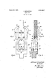
- Fig. 1 is a front elevation of the movable cutter member (or chisel member).
- Fig. 2 is a longitudinal section of the same on its centre line.
- Fig. 3 is a front elevation of the stationary member containing the internal guide for the chisel member
- Fig. 4 is a longitudinal section of Figure 3 on its centre line.
- the movable or chisel-member is indicated by 5, its curved and angular cutting edge by 6, this being preferably on a separate and removable member 7
- the body of the member 5 terminates in the hammer-faced projections 8 and has on each side extensions or ears 9 which carry the fulcrum pins 10 of the two levers 11.
- These levers each have at their free ext-remities a claw-like projection 12 which acts as a ratchet catch to secure the linear effect of the hammer blow delivered upon the face 8.
- the levers 11 are held in engagement with the ratchet rack by the helical extension spring 13 which engages both levers at 14.
- the body of the U-shaped member is indicated at 15. i
- This member also has a projection 16 on its outer end which acts as a convenient pedestal or foot.
- the interior of the U-shaped member has a slide and guide 17 suitable to receive the cutter end of the chisel-member 5, and has also a corresponding concavely curved angular cutting edge 18 also removably attached to the body member.
- the two cutters come into slidable contact with each other on a flat face 19 and thus effect a perfect shearing action on the cable inserted between them.
- a ratchet rack '20 On each side of the member 15 is formed a ratchet rack '20.
- the angularity of these teeth are such that their apices point downwards towards the foot 16 and thus serve to retain the claw ended levers when the chisel member is struck for the purpose of severmg a cable.
- the said means comprisingclaw-like arms in pivotal connection with the said hammer driven cutter engaging corresponding ratchet-racks on the other said cutter.
- a device for cutting cables comprising, a U-shaped member having a foot projecting from its closed end, parallel guides opposite each other on the inner sides of the said U-shaped member, a concavely curved angular edged cutter at the inner end of said guides, a ratchet-like rack formed on the outer sides of the said V- shaped member, a chisel member having a concavely curved angular-edged cutter at one extremity and a hammer-faced projection at the other extremity, the said chisel member being adapted to slidably contact the said U-shaped member and to movably fit within the said guide, ears extending from the sides of the said chisel member, the said ears carrying pivotal pins, a pivotal claw-like arm of the character of an elongated C on eaehside of'said chisel'member fulcrumed on said pins, the claw-like e2:- tremities of the
Landscapes
- Engineering & Computer Science (AREA)
- Mechanical Engineering (AREA)
- Shearing Machines (AREA)
Description
March 20, 1928 A. BERGSTROM CABLE CUTTER Filed Jan. 13. 1927 J5 [free (1 fiazys'izbm Patented Mar. '20, 1928.
airs.
ALFRED BEB-GSTBOM, or vancouvnn, Barrier: COL MBIA, cAnAnn.
CABLE CUTTER.
Application filed January 13, 1927. Serial No. 160,891.
This, invention relates to aportable cable cutting device and has for its object the provision of a tool of this character which is simple in form, easily used and transported and cannot readily be injured by the rough usage to which such tools are invariably subopposing concavely curved steel cutters slidmg in a guide against each other in the same plane, thus producing a perfect shearing stress on the cable, the stress being effected by hammer blows which are followed up by a simple ratchet device to retain their successive effect and prevent any rebound of the cutters. I
The invention is fully described in the specification following together with the drawings herewith which form part of this application and in which:
Fig. 1 is a front elevation of the movable cutter member (or chisel member).
Fig. 2 is a longitudinal section of the same on its centre line.
' Fig. 3 is a front elevation of the stationary member containing the internal guide for the chisel member, and
Fig. 4 is a longitudinal section of Figure 3 on its centre line.
Taking the drawings in detail and noting that similar numerals in the different views indicate identical parts, the movable or chisel-member is indicated by 5, its curved and angular cutting edge by 6, this being preferably on a separate and removable member 7 The body of the member 5 terminates in the hammer-faced projections 8 and has on each side extensions or ears 9 which carry the fulcrum pins 10 of the two levers 11. These levers each have at their free ext-remities a claw-like projection 12 which acts as a ratchet catch to secure the linear effect of the hammer blow delivered upon the face 8. The levers 11 are held in engagement with the ratchet rack by the helical extension spring 13 which engages both levers at 14.
The body of the U-shaped member is indicated at 15. i This member also has a projection 16 on its outer end which acts as a convenient pedestal or foot. The interior of the U-shaped member has a slide and guide 17 suitable to receive the cutter end of the chisel-member 5, and has also a corresponding concavely curved angular cutting edge 18 also removably attached to the body member.
The two cutters come into slidable contact with each other on a flat face 19 and thus effect a perfect shearing action on the cable inserted between them.
On each side of the member 15 is formed a ratchet rack '20. The angularity of these teeth are such that their apices point downwards towards the foot 16 and thus serve to retain the claw ended levers when the chisel member is struck for the purpose of severmg a cable. In this connection it may be,
noted that in practical usethe claws do not wear the ratchet points so much as they deepen the tooth and increase the holding effect.
Having now particularly described my invention, what I claim and desire to be protected in by Letters Patent, is:
, 1. In a device for cutting cables the combination comprising, a pair of concavely.
curved angular edged cutters sliding one against the other, one of said cutters being adapted to slide past the other by hammer blows delivered upon a projection on it, and
means for intercepting the reaction of the said blows upon the cutter so that the latter may be in effective contact with a cable during successive blows, the said means comprisingclaw-like arms in pivotal connection with the said hammer driven cutter engaging corresponding ratchet-racks on the other said cutter.
2. In a device for cutting cables the combination comprising, a U-shaped member having a foot projecting from its closed end, parallel guides opposite each other on the inner sides of the said U-shaped member, a concavely curved angular edged cutter at the inner end of said guides, a ratchet-like rack formed on the outer sides of the said V- shaped member, a chisel member having a concavely curved angular-edged cutter at one extremity and a hammer-faced projection at the other extremity, the said chisel member being adapted to slidably contact the said U-shaped member and to movably fit within the said guide, ears extending from the sides of the said chisel member, the said ears carrying pivotal pins, a pivotal claw-like arm of the character of an elongated C on eaehside of'said chisel'member fulcrumed on said pins, the claw-like e2:- tremities of the said arms being adapted to each engage the ratchet-like rack on each corresponding side of the said U-shaped member, the engagement of the said claws and the said'rack being adapted to prevent any appreciable backward movement of the said chisel member When the latter is driven into the said guide by hammer blows, a helical spring uniting the two said members at points intermediate thesaid pivot pins and said claw-like extremities, said spring being adapted to cause the engagement of the said claws With the said racks.
In testimony wherebf I afiix my signature.
ALFRED BERGSTROM.
Priority Applications (1)
| Application Number | Priority Date | Filing Date | Title |
|---|---|---|---|
| US160891A US1663189A (en) | 1927-01-13 | 1927-01-13 | Cable cutter |
Applications Claiming Priority (1)
| Application Number | Priority Date | Filing Date | Title |
|---|---|---|---|
| US160891A US1663189A (en) | 1927-01-13 | 1927-01-13 | Cable cutter |
Publications (1)
| Publication Number | Publication Date |
|---|---|
| US1663189A true US1663189A (en) | 1928-03-20 |
Family
ID=22578902
Family Applications (1)
| Application Number | Title | Priority Date | Filing Date |
|---|---|---|---|
| US160891A Expired - Lifetime US1663189A (en) | 1927-01-13 | 1927-01-13 | Cable cutter |
Country Status (1)
| Country | Link |
|---|---|
| US (1) | US1663189A (en) |
Cited By (7)
| Publication number | Priority date | Publication date | Assignee | Title |
|---|---|---|---|---|
| US2934860A (en) * | 1955-03-01 | 1960-05-03 | Rca Corp | Tip-off apparatus for electron tubes |
| US3474533A (en) * | 1967-05-17 | 1969-10-28 | Etco Inc | Explosive cutter for cables and the like |
| US4285126A (en) * | 1979-09-04 | 1981-08-25 | Lawrence Irwin F | Hydraulically actuated apparatus |
| US5775158A (en) * | 1996-07-23 | 1998-07-07 | Greenlee Textron Inc. | Cutting dies |
| US20130305896A1 (en) * | 2012-03-23 | 2013-11-21 | The National Telephone Supply Company | Cutter dies |
| US20140182441A1 (en) * | 2012-03-23 | 2014-07-03 | Philip J Pisczak | Cutter dies |
| US20150283629A1 (en) * | 2012-08-07 | 2015-10-08 | Wobben Properties Gmbh | Pre-stressing tendon separation device |
-
1927
- 1927-01-13 US US160891A patent/US1663189A/en not_active Expired - Lifetime
Cited By (8)
| Publication number | Priority date | Publication date | Assignee | Title |
|---|---|---|---|---|
| US2934860A (en) * | 1955-03-01 | 1960-05-03 | Rca Corp | Tip-off apparatus for electron tubes |
| US3474533A (en) * | 1967-05-17 | 1969-10-28 | Etco Inc | Explosive cutter for cables and the like |
| US4285126A (en) * | 1979-09-04 | 1981-08-25 | Lawrence Irwin F | Hydraulically actuated apparatus |
| US5775158A (en) * | 1996-07-23 | 1998-07-07 | Greenlee Textron Inc. | Cutting dies |
| US20130305896A1 (en) * | 2012-03-23 | 2013-11-21 | The National Telephone Supply Company | Cutter dies |
| US20140182441A1 (en) * | 2012-03-23 | 2014-07-03 | Philip J Pisczak | Cutter dies |
| US20150283629A1 (en) * | 2012-08-07 | 2015-10-08 | Wobben Properties Gmbh | Pre-stressing tendon separation device |
| US9962776B2 (en) * | 2012-08-07 | 2018-05-08 | Wobben Properties Gmbh | Pre-stressing tendon separation device |
Similar Documents
| Publication | Publication Date | Title |
|---|---|---|
| US1663189A (en) | Cable cutter | |
| US2295385A (en) | Pruning shears | |
| US1741109A (en) | Latch for pivoted handles | |
| US2389648A (en) | Container-opening tool | |
| US2053707A (en) | Tool guard | |
| US2452148A (en) | Adjustable keyhole saw | |
| US2441475A (en) | Hand combat weapon | |
| US1216889A (en) | Envelop-opener. | |
| US1672458A (en) | Tool for removing and inserting saw teeth | |
| US2105960A (en) | Razor blade scraper | |
| GB249289A (en) | Improvements in or relating to nippers, pliers, or the like | |
| US2715769A (en) | Wire cutting and retaining nipper | |
| US2372534A (en) | Chain saw | |
| US1535661A (en) | Saw guide and square | |
| US888606A (en) | Pliers. | |
| US2850923A (en) | Chain saw cutter file holder | |
| US1664529A (en) | Tool | |
| US1896912A (en) | Cable cutter | |
| US2093900A (en) | Rope binding means | |
| US2432121A (en) | Cable serving device | |
| US2211525A (en) | Mine machinery cutting bit and mounting therefor | |
| US1887220A (en) | Gauge | |
| US1941221A (en) | Glass cutter | |
| US1743811A (en) | Concrete-form-binding tool | |
| US1297565A (en) | Saw setting and filing tool. |