US1663187A - Multiple timer - Google Patents
Multiple timer Download PDFInfo
- Publication number
- US1663187A US1663187A US31575A US3157525A US1663187A US 1663187 A US1663187 A US 1663187A US 31575 A US31575 A US 31575A US 3157525 A US3157525 A US 3157525A US 1663187 A US1663187 A US 1663187A
- Authority
- US
- United States
- Prior art keywords
- hand
- dial
- contacts
- clock
- indicated
- Prior art date
- Legal status (The legal status is an assumption and is not a legal conclusion. Google has not performed a legal analysis and makes no representation as to the accuracy of the status listed.)
- Expired - Lifetime
Links
- 238000011282 treatment Methods 0.000 description 8
- 230000000875 corresponding effect Effects 0.000 description 3
- RNAMYOYQYRYFQY-UHFFFAOYSA-N 2-(4,4-difluoropiperidin-1-yl)-6-methoxy-n-(1-propan-2-ylpiperidin-4-yl)-7-(3-pyrrolidin-1-ylpropoxy)quinazolin-4-amine Chemical compound N1=C(N2CCC(F)(F)CC2)N=C2C=C(OCCCN3CCCC3)C(OC)=CC2=C1NC1CCN(C(C)C)CC1 RNAMYOYQYRYFQY-UHFFFAOYSA-N 0.000 description 1
- 238000003780 insertion Methods 0.000 description 1
- 230000037431 insertion Effects 0.000 description 1
- 238000009413 insulation Methods 0.000 description 1
- 239000012780 transparent material Substances 0.000 description 1
Images
Classifications
-
- G—PHYSICS
- G04—HOROLOGY
- G04C—ELECTROMECHANICAL CLOCKS OR WATCHES
- G04C23/00—Clocks with attached or built-in means operating any device at preselected times or after preselected time-intervals
- G04C23/14—Mechanisms continuously running to relate the operation(s) to the time of day
- G04C23/18—Mechanisms continuously running to relate the operation(s) to the time of day for operating one device at a number of different times
- G04C23/20—Mechanisms continuously running to relate the operation(s) to the time of day for operating one device at a number of different times with contacts operated, or formed by clock hands or elements of similar form
Definitions
- One ofthe objects of this invention is toprovide a time-piece by which the treatment of a patient can be easily and properly timed from any,- given moment or from the beginning of the treatment.
- Another object isto provide a device by which a patients treatment can be conveniently checked.
- Another object is to provide a device by i which the treatments of any number of patients can be timed over various periods.
- Another object is to provide a device by which the period of a patients treatment can be indicated audibly.
- Another object is to provide a device by which various'periods may be audibly indicated.
- Another object is to provide a device em bodying a time-piece and a dial for indicating various periods, having signals arranged in certain relation to the indicated periods.
- Another object is to provide a device embodying. a time-piece and signals, by which any desired period may be visibly and audibly indicated. a
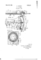
- Wliich Fig. 1 is a fra on line-1l1.of ig. 2, illust-rating a portion of a clockwork with a hand in operative connection with electric contacts.
- Fig. 2 is a fragmentary front elevation ofa dial and time-indicating handv with computing dial in operative relation to contactsockets.
- Fig. 3 is a somewhat diagrammatical rearside elevation of the inner apparatus of the device as disposed ina cabinet, the cabinet being illustrated in vertical section.
- a clock-work 4 serves as the actuator of the indicator as illustrated in the drawing.
- the indicating hand 5 is in operative connection with the clockworke
- the clockwork may, of course,-be of any desired make, to indicate: anything suitable forthe purpose for which the Whole device may be applied.
- the hand may be made toindicate the time by hour or minute or any other desirable period. 7
- the indicated time may be divided into any desirable fraction.
- Fig.- 2 a portion of a common dial. of a clock is illustrated,,showing the main figures II, III and H11, and fivev positions or. spaces between the different figures, being the equivalents of minutes in a common clock.
- It the illustrated hand 5 is. considered the common-clock hour-hand, a movement of the hand from one indicated: position to the next position would be the equivalent of twelve minutes, while the minute-hand of a common clock would move in one minute from one position to the next.
- the hand 5 moves as from II to III and from III to IIII in fiverninutes, and. the hand moves a full turn back to the starting point in sixty minutes.
- Contacts 6 are provided in the dial of the clock in the path over which the hand moves in its regular manner, the contacts being disposed so that the hand contacts with the top surfaces of the contacts 6.
- sixty contacts have been provided so that the hand 5 may come into operative engagement with one of the contacts every minute as the hand moves over the face or dial of the clock. More or less contacts may of course be provided, to allow a contact-making for any desired periods.
- Each of the contacts 6 is provided with a circuit-break, which may be closed by a plug, so that the contact-making may made effective at a certain minute of the full rotating movement of the hand. Any numher of plugs may be used, so that several contacts may be in a closed circuit as the hand moves over such contacts during its regular movement.
- Sockets 7 are provided in a number cor responding to the number of contacts 6, and a connection 8 is provided between each pair of contacts 6 and sockets 7
- a contact-ring 9 is mounted on the insulation ring 10 in a position that the circuit may be closed between any of the connections 8 and the ring 9 by a plug 11 disposed in any of the socket-s 7, as illustrated in Fig. 1.
- a circuit may then be formed and closed between the lead 12, the clock-work 1, the hand 5, the contact 6, the connection 8, the plug 11, the contact-ring 9, and the lead 13 back to the lead 12, considering that a battery and other instruments may be inserted between the leads 12 and 13 as illustrated inFig. 1 even though no such insertions are indicated in that illustration.
- FIG. 3 a diagrammatic illustration of instruments and leads shows more clearly a simple form of forming a proper circuit in connection with the above described parts of the apparatus described so far.
- An electric socket 1 1, of any well known make, is indicated in the side wall of the cabinet 15.
- the leads 16 and 17 connect the socket 14 with the transformer 18.
- a buzzer 1.9 is connected to the transformer 18 by the lead 20 on one side, and has the lead 13 as a second connection.
- the buzzer may in such case be-a low current instrument, and the transformer may be selected to take care of any current to be supplied to the socket 14.
- the computing dial may be of transparent material or may even be ofmetal as long as the hand alone is allowed to make contact.
- the zero-figure is preferably in alignment with the hand 5, so as to simplify and facilitate a computing of time from the moment to extend over any period of time.
- any desired or required period to begin at III may be directly read off on the computing dial, and a plug may be inserted into the socket of the series 7, to assure a closing of the circuit as soon as the hand comes to a point over the corresponding contact of the series v6.
- the computing dial 523 and the hand 5 are for this purpose preferably firmly or frictionally interconnected, so that the computing'dial will always be with its zero-mark inalignment with the position of the hand 5.
- the whole ap- 'paratus' may be arranged to co-act' with the hour-hand of a clock-work, so that several hours and including certain minutes may be plugged off to indicate the termination of a certain period, and several different periods of time may be indicated beginning at vari-- ous times of the day.
- the plugs 11 preferably carry numbers to correspond with the numbers of the rooms of a hotel, or to correspond with the nuinbers of the treatment rooms of clients.
- a multiple timer in combination with a clockwork including dial and indicating hand carried by a central shaft of the clockwork, the central shaft and therewith the hand being in continuous operative connection with one terminal, indicating members having head pieces disposed on the outside of said dial to contact with the, free end of said indicating hand at desired points throughout the circle of the dialand terminating on the rear-side of the dial carrying a contact member in operative connection with a second terminal normally insulated from the first-named terminal, a second contact member having its free end'disposed spaced from the free end of the firstnamed contact member thereby normally forming a gap in a circuit while in direct connection with the said indicating member the said gap on the rear-side of said dial and thereby with the said first-named termifor closing the circuit and at a point adj anal when the said hand is disposed over the cent to each of said indicating members.
Landscapes
- Physics & Mathematics (AREA)
- General Physics & Mathematics (AREA)
- Electric Clocks (AREA)
Description
March 20', 1928. 1,663,187
T. J. BARRETT MULTIPLE TIMER Filed May 20, 1925 a a 4 /4 l J41 8 A UK u T'uorms =1. Banner-r,
Patented Mar. 20, 1928.
THOMASJ'. BARRETT, OF LOS ANGELES,
IU'LTIPLE TIMER.
Application filed Kay 20, 1825. Serial No. 31,575.
One ofthe objects of this invention is toprovide a time-piece by which the treatment of a patient can be easily and properly timed from any,- given moment or from the beginning of the treatment.
Another object isto provide a device by which a patients treatment can be conveniently checked.
Another object is to provide a device by i which the treatments of any number of patients can be timed over various periods.
1 Another object is to provide a device by which the period of a patients treatment can be indicated audibly.
Another objectis to provide a device by which various'periods may be audibly indicated.
Another objectis to providea device em bodying a time-piece and a dial for indicating various periods, having signals arranged in certain relation to the indicated periods. I
Another object is to provide a device embodying. a time-piece and signals, by which any desired period may be visibly and audibly indicated. a
Other objectswill appear from the following description and appended claim as well as from the accompanying drawing, in Wliich Fig. 1 is a fra on line-1l1.of ig. 2, illust-rating a portion of a clockwork with a hand in operative connection with electric contacts.
Fig. 2 is a fragmentary front elevation ofa dial and time-indicating handv with computing dial in operative relation to contactsockets.
Fig. 3 is a somewhat diagrammatical rearside elevation of the inner apparatus of the device as disposed ina cabinet, the cabinet being illustrated in vertical section.
Patients are frequently put under treatment for certain periods, and at places where a number of patients are treated for various periods at different times it is not an easy entary horizontal section task to time the: treatments. of. the variousto patients conveniently or properly.
In hotels and at other places where: certain periods or times are desired tobe indicated'with a certain degreev of correctness and punctuality it is also of greatimportance to have mechanically operated. indicators.
Though a certain arrangement with certain parts are illustrated in thedrawing, it must be understood that the illustrations'in' the drawing are merely to-serve to facilitate a description ofthe invention, and that the different parts may bevaried to quite an extent within the scope oi the accompanying claims.
A clock-work 4 serves as the actuator of the indicator as illustrated in the drawing. The indicating hand 5 is in operative connection with the clockworke The clockwork may, of course,-be of any desired make, to indicate: anything suitable forthe purpose for which the Whole device may be applied.
Taking a common clockwork, the hand may be made toindicate the time by hour or minute or any other desirable period. 7
The indicated time may be divided into any desirable fraction.
11 Fig.- 2, a portion of a common dial. of a clock is illustrated,,showing the main figures II, III and H11, and fivev positions or. spaces between the different figures, being the equivalents of minutes in a common clock. It the illustrated hand 5 is. considered the common-clock hour-hand, a movement of the hand from one indicated: position to the next position would be the equivalent of twelve minutes, while the minute-hand of a common clock would move in one minute from one position to the next.
For the sake of simplicity, the invention willbe described with reference to the movements of a common clockwork, and with ref.- erence to the movement of the minute-hand or larger hand of a common clock.
Under these conditions, the hand 5 moves as from II to III and from III to IIII in fiverninutes, and. the hand moves a full turn back to the starting point in sixty minutes.
Contacts 6 are provided in the dial of the clock in the path over which the hand moves in its regular manner, the contacts being disposed so that the hand contacts with the top surfaces of the contacts 6.
As illustrated, sixty contacts have been provided so that the hand 5 may come into operative engagement with one of the contacts every minute as the hand moves over the face or dial of the clock. More or less contacts may of course be provided, to allow a contact-making for any desired periods.
Each of the contacts 6 is provided with a circuit-break, which may be closed by a plug, so that the contact-making may made effective at a certain minute of the full rotating movement of the hand. Any numher of plugs may be used, so that several contacts may be in a closed circuit as the hand moves over such contacts during its regular movement.
A circuit may then be formed and closed between the lead 12, the clock-work 1, the hand 5, the contact 6, the connection 8, the plug 11, the contact-ring 9, and the lead 13 back to the lead 12, considering that a battery and other instruments may be inserted between the leads 12 and 13 as illustrated inFig. 1 even though no such insertions are indicated in that illustration.
In Fig. 3, a diagrammatic illustration of instruments and leads shows more clearly a simple form of forming a proper circuit in connection with the above described parts of the apparatus described so far. An electric socket 1 1, of any well known make, is indicated in the side wall of the cabinet 15. The leads 16 and 17 connect the socket 14 with the transformer 18. A buzzer 1.9 is connected to the transformer 18 by the lead 20 on one side, and has the lead 13 as a second connection.
Considering that the parts described above with reference to Fig. 1 are inserted between the leads 12 and 13 in one direction, the circuit between the leads 12 and 13 is in this form closed by the transformer, the lead 20, the buzzer 19, and the return to lead 13.
The buzzer may in such case be-a low current instrument, and the transformer may be selected to take care of any current to be supplied to the socket 14.
Considering that the hand 5 points to III of the main dial of the clock, and, since this description has been made with reference to the minute-hand of a common clock, assum-.
ing that four minutes are to be timed by this apparatus without having to pay attention to any other time-piece, a plug is merely inserted into the socket at 21. The circuit described above will be closed as soon as the hand 5 comes to a point over the corresponding contact, that is in the illustration of Fig. 2 shown below the indication next to the small numeral 4-, indicated at 22, in the computing dial 23.
The computing dial may be of transparent material or may even be ofmetal as long as the hand alone is allowed to make contact. Providing a number of computing figures on the computing dial 28, the zero-figure is preferably in alignment with the hand 5, so as to simplify and facilitate a computing of time from the moment to extend over any period of time. Inasmuch as the hand 5 points toward III, and considering that the hand is in alignment with zero of the computing dial 23, any desired or required period to begin at III may be directly read off on the computing dial, and a plug may be inserted into the socket of the series 7, to assure a closing of the circuit as soon as the hand comes to a point over the corresponding contact of the series v6. The computing dial 523 and the hand 5 are for this purpose preferably firmly or frictionally interconnected, so that the computing'dial will always be with its zero-mark inalignment with the position of the hand 5.
Of course, as stated above, the whole ap- 'paratus'may be arranged to co-act' with the hour-hand of a clock-work, so that several hours and including certain minutes may be plugged off to indicate the termination of a certain period, and several different periods of time may be indicated beginning at vari-- ous times of the day.
The plugs 11 preferably carry numbers to correspond with the numbers of the rooms of a hotel, or to correspond with the nuinbers of the treatment rooms of clients.
Having thus described my invention, I claim:
In a multiple timer, in combination with a clockwork including dial and indicating hand carried by a central shaft of the clockwork, the central shaft and therewith the hand being in continuous operative connection with one terminal, indicating members having head pieces disposed on the outside of said dial to contact with the, free end of said indicating hand at desired points throughout the circle of the dialand terminating on the rear-side of the dial carrying a contact member in operative connection with a second terminal normally insulated from the first-named terminal, a second contact member having its free end'disposed spaced from the free end of the firstnamed contact member thereby normally forming a gap in a circuit while in direct connection with the said indicating member the said gap on the rear-side of said dial and thereby with the said first-named termifor closing the circuit and at a point adj anal when the said hand is disposed over the cent to each of said indicating members. 10 head piece of said indicating member, and In testimony that I claim the foregoing 5 a plug receiving means disposed at a point as my invention I have signed my name.
to brin an inserted plug between the two free en s of said contact members to bridge THOMAS J. BARRETT.
Priority Applications (1)
| Application Number | Priority Date | Filing Date | Title |
|---|---|---|---|
| US31575A US1663187A (en) | 1925-05-20 | 1925-05-20 | Multiple timer |
Applications Claiming Priority (1)
| Application Number | Priority Date | Filing Date | Title |
|---|---|---|---|
| US31575A US1663187A (en) | 1925-05-20 | 1925-05-20 | Multiple timer |
Publications (1)
| Publication Number | Publication Date |
|---|---|
| US1663187A true US1663187A (en) | 1928-03-20 |
Family
ID=21860218
Family Applications (1)
| Application Number | Title | Priority Date | Filing Date |
|---|---|---|---|
| US31575A Expired - Lifetime US1663187A (en) | 1925-05-20 | 1925-05-20 | Multiple timer |
Country Status (1)
| Country | Link |
|---|---|
| US (1) | US1663187A (en) |
-
1925
- 1925-05-20 US US31575A patent/US1663187A/en not_active Expired - Lifetime
Similar Documents
| Publication | Publication Date | Title |
|---|---|---|
| CH622926B (en) | ELECTRONIC WATCH LIKELY TO SIMULATE A GAME OF CHANCE. | |
| US1663187A (en) | Multiple timer | |
| US1989584A (en) | Timepiece | |
| GB191517281A (en) | Apparatus for Teaching Children and others to Ascertain the Time from Clocks. | |
| GB918612A (en) | Improvements in simulated swinging pendulum clock | |
| FR2312813A1 (en) | WATCH WITH ELECTRONIC STOP | |
| US2363763A (en) | Clock | |
| US1393569A (en) | Dial | |
| US2098965A (en) | Clock | |
| US2477857A (en) | Annunciator | |
| US2124490A (en) | Electric call board for hotels | |
| US2514948A (en) | Wind velocity indicator | |
| US1369146A (en) | Signaling system | |
| US1506337A (en) | Signal for time locks | |
| FR2438863A1 (en) | SEQUENTIAL DISPLAY FOR DIGITAL CHRONOGRAPH | |
| JPS5337074A (en) | Digital display chronograph watch | |
| US556428A (en) | Electric program-clock | |
| US3133405A (en) | Time registering device | |
| SU58595A1 (en) | Aneorumbometer | |
| US1706410A (en) | Time switch | |
| US459917A (en) | Contact for electric programme-clocks | |
| US2417368A (en) | Mechanism for controlling electric circuits | |
| GB214364A (en) | Apparatus for audibly signalling periods of time | |
| US1336318A (en) | Electric clock and signal system | |
| SU832523A1 (en) | Electronic time-piece |