US1663148A - Grinding machine - Google Patents
Grinding machine Download PDFInfo
- Publication number
- US1663148A US1663148A US424898A US42489820A US1663148A US 1663148 A US1663148 A US 1663148A US 424898 A US424898 A US 424898A US 42489820 A US42489820 A US 42489820A US 1663148 A US1663148 A US 1663148A
- Authority
- US
- United States
- Prior art keywords
- carriage
- lever
- shaft
- sleeve
- guard
- Prior art date
- Legal status (The legal status is an assumption and is not a legal conclusion. Google has not performed a legal analysis and makes no representation as to the accuracy of the status listed.)
- Expired - Lifetime
Links
- 241000282472 Canis lupus familiaris Species 0.000 description 18
- 230000002441 reversible effect Effects 0.000 description 6
- 230000007935 neutral effect Effects 0.000 description 5
- XLYOFNOQVPJJNP-UHFFFAOYSA-N water Substances O XLYOFNOQVPJJNP-UHFFFAOYSA-N 0.000 description 3
- 238000013459 approach Methods 0.000 description 2
- 241000283690 Bos taurus Species 0.000 description 1
- 230000006978 adaptation Effects 0.000 description 1
- 238000010276 construction Methods 0.000 description 1
- 238000005520 cutting process Methods 0.000 description 1
- 230000003247 decreasing effect Effects 0.000 description 1
- 210000005069 ears Anatomy 0.000 description 1
- 239000011435 rock Substances 0.000 description 1
Images


Classifications
-
- B—PERFORMING OPERATIONS; TRANSPORTING
- B24—GRINDING; POLISHING
- B24B—MACHINES, DEVICES, OR PROCESSES FOR GRINDING OR POLISHING; DRESSING OR CONDITIONING OF ABRADING SURFACES; FEEDING OF GRINDING, POLISHING, OR LAPPING AGENTS
- B24B5/00—Machines or devices designed for grinding surfaces of revolution on work, including those which also grind adjacent plane surfaces; Accessories therefor
- B24B5/02—Machines or devices designed for grinding surfaces of revolution on work, including those which also grind adjacent plane surfaces; Accessories therefor involving centres or chucks for holding work
- B24B5/06—Machines or devices designed for grinding surfaces of revolution on work, including those which also grind adjacent plane surfaces; Accessories therefor involving centres or chucks for holding work for grinding cylindrical surfaces internally
Definitions
- My said invention relates to grinding machines intended primarily for internal grinding as for smoothingl the inside of the hub of a wheel or pulley aving an internal hearing surface, and my main object is to provide a machine that is automatic in its operation, and that requires a minimum of attention into operation.
- Another object is to provide a construction in which the work stops when the grinding wheel is withdrawn from it.
- Another object is to provide means for adjusting the length. and position of the stroke.
- Another object is to provide a work holder capable of being turned a few degrees so as to rind a tapered surface.
- Still another object is to provide shields for both the work and the grinding wheel to protect the workman.
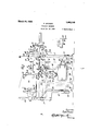
- Figure 1 is a front elevation of the complete machine, with the carriage stationary and out of working position.
- Figure 3 a vertical section on line 3-3, Figure 2, the parts being in working position.
- Figure 6 a'detail of parts of a guard shown in Figure 1.
- reference character A indicates the fixed frame of a grinding machine, said frame being a closed casing aving the usual doors, bearings, etc. and also having superposed thereon a work holder B and a reciprocating carriage C for a inding wheel w.
- a belt connected with a source of power drives a pulley 11 fast to main This shaft has fast thereon two stepped pulleys 13 and 14.
- a sleeve 15 is splined to shaft .12 and has a cone clutch member at each end adapted mo. Serial 80. 424,808.
- Sleeves 16 and 17 have gear teeth 18 and 19 inte ral therewith respectively and both sets 0 teeth are in constant enga ement with a gear 20 on a shaft 21.
- T is shaft is mounted in a bearing 22 carried by lugs 23 and 24 on the frame of the machine.
- the hearing has a slot at one side through which a worm 25 engages with a worm wheel 26 on a vertical sha t 27 which drives wheel carriage C (Fig. 3) by means of a pinion 28 on the shaft in engagement with a rack 29 on the carriage.
- the clutch sleeve 15 is shifted from side to side by means here inafter described the wheel carriage is moved back and forth on its track.
- the fast pulleys 13 and 14 abut against the ends of sleeves 16 and 17 to hold them in place.
- a fast pulley 30 at the far end of the shaft drives a pump to rovide for the circulation of water, this being no part of mympresent invention.
- a t 31 driven by pulley 13 passes over a step ed pulley 32 loose on a counter-shaft 33 an has integral therewith, or fixed thereto, a small pulley 34 which by means of belt 35 and ulley 36 drives shaft 37.
- This shaft has a c utch sleeve 38 splined thereto, said sleeve having oppositely projeetin teeth.
- Sleeves 39 and 40 loose on shaft 3 carry teeth adapted to engage alternately with those of the sleeve 38 and the also carry gear teeth 41 and 42 respective y which are in constant engagement with a gear 43, on shaft 21.
- This hand wheel is intended for operatin the machine when the power is off.
- the ot er sleeve 39 is held in place by a collar 47 fixed to shaft 37 by a set-screw and having a flan e 48 engaging a groove in the collar. It wi l he noted that the belt caring provides for driving shaft 37 at a ow speed, and this is again decreased by gears 41, 42, and 43 to slow down shaft 21.
- the carriage C may thus be driv on either by hand or power at a low normal speed, or it may be driven at a high speed to move it out of and away from the work, high speed being attained when shaft 21 is driven by gear from gear 18 or 19.
- Pulley 14 drives a stepped pulley by means of a belt 49, this pulley being loosely held on shaft 33 between two collars 51 and 52.
- the pulley has a tapered surface forming a clutch member 53 to engage with a clutch member 53' on a sleeve 54.
- a conical member 55 At the opposite end of the sleeve is a conical member 55 adapted to engage a braking surface 56 on a cylindrical member 57 located in an opening of the fixed frame and carrying a bearing for shaft 33.
- a spring 58 normally forces the clutch members into en agement.
- he sleeve 54 has a shifter 59 on a shaft 60 actuated by a train of mechanism comprising a rock-arm 61, an elastic tension device 62, a link 63, and a lever 64 pivoted at 65 and having a roller at its free end for engagement by a cam 64 on the wheel carriage.
- Sleeve 54 is splined to shaft 33 and when clutch members 53, 53 are in engagement shaft 33 will be driven, thus drlving pulley 66, belt 67, pulley 68 and work-holder 69 in the form of a rotary spindle, which might be embodied in various forms and might have movements other than simple rotatlon, within the limits of my invention, which carries pulley 68 substantially in line with the axis on Wl'llCh the support is rotarily adjustable so as to maintain proper alignment of belt 68 and its pulleys. Contrariwise, cone 55 acts as a brake for the workholder and the train of gearing leading thereto.
- a clutch shifter 70 (Figs. 1 and 3) having a handle portion 71 is pivoted at 72 for movement toward and from the machine and is also movable laterally thereof on shaft 73 as a pivot, the enlargement at 72 sliding in a slot of the machine frame.
- a hood 74 formed on the handle 71 covers the slot to revent access of water and grit.
- Shaft 73 has a sleeve 73 concentric therewith for moving a clutch-fork 38 which controls reversing sleeve 38 and the lever 70 has a clutch sleeve 75 pivotally connected thereto at 76 in a fork at its lower end and slidable on shaft 73.
- a forked extension 70 of sleeve 75 carries a roller 76 cooperating with a yieldable detent 77 set in a casing A on the machine frame to hold the lever 70 in front or rear position.
- the spring 78 of the detent is introduced through an opening normally closed by a screw-plug 79.
- the casing A also has a door A for access to the lower end of lever 70 and adjacent parts.
- lever 70 With lever 70 in the position shown in Fi 3 the teeth of sleeve 75 engage sleeve 73 to operate reversing sleeve 38 as in the normal working of the machine with the wheel carriage reciprocating slowly. If the portion 71 of lever 70 is now forced the machine sleeve 75 will be unclutched from sleeve 73' and engaged with a clutch member 80 on shaft 73. Lateral movement of lever 70 will now rock shaft 73, clutch fork 81 and reversing sleeve 15. As lever 70 moves sleeve 75 out of en agement with sleeve 73', the extension 70 ra s a bar 82 with it.
- This bar slides in a gui e on the machine frame and is fixed at one end to extension 70 to move therewith and also extends through an opening of a downward extension 83 on sleeve 73'.
- This opening is preferably tapered to correspond to a tapered ortion of the bar and the sleeve is moved a central position and locked therein, thus locking the reversing sleeve 38 in central inactive position.
- Cluteh-fork 81 is similarly moved toward central position from one side by a yieldable abutment 81' on the frame, the shaft 73 and its clutch member 80 being moved to neutral position by dog 91) to stop the carriage and further movement being opposed by abutment 81.
- he carriage C which is here shown as bearing the grinding wheel 10, but which may carry the work operated on, or an abrading device of different character, or other object, if desired, consists mainly of two parts, viz, a base C slidable lengthwise of the machine frame A, and a support C here shown as carrying the wheel and its driving devices, said support being adjustable transverse] of the base.
- the wheel w and its spind e 84 are driven at high speed in a direction opposite to that in which the work rotates, by a pulley on the spindle driven by a belt 85.
- a belt 86 connected to a source of power (not shown) drives pulley 87 which 1s on the same shaft with pulley 88 that drives belt 85.
- a dog ng device for lever 70 moves back and fort in time with the carriage being preferably rigidly fastened thereto, and comprises a rod 89 having rack teeth 89' on its under side and carrying a fixed abutment or dog 90 at one end. Dogs 91 and 92 are adjustable on the rod. each one having a worm 93 on a journal pivoted at one end to the dog and spring pressed toward the rack. By swinging the worm away from the rack a rough and quick adjustment may be made and thereafter an accurate adj ustment by turnin the worm.
- dogs 91 and 92 strike against a spring-supported engaging lug 94 on lever 70 and move it to and fro to reverse whichever clutch-revers ing sleeve may be operative at the time.
- the dog 91 has a downward incline 95 to force the lug 94 back against the pressure of its spring as hereinafter described and is also cut away at the other side to form an inclined face 94'.
- a guard or shield 96 is provided to keep the operator from touching wheel w and to handle toward ed as at 113 and provide protect him from flying cuttings, water and the like. -This guard is sup orted on a rod 97 slidable with respect to t e carriage C.
- Rod 97 has a sleeve 98 slidable thereon at one end and the sleeve has spring fingers 99 for engagement with opposite sides of a stationary rod 100.
- Rod 100 is supported on a bracket 101 fixed on the frame at 102.
- An abutment C is adapted to engage the opposite end of sleeve 98.
- a second guard 103 is provided for the workholder 69 and this guard is pivoted at 104 for movement as b a handle 105'into the dash line sition an back to the full line sltlon w ere it completely covers the work.
- This stub shaft has a depending bracket 108 to receive a rod 109 clamped in place by screw 110 which su rts a device, e. g., for train the wheel.
- e stub shaft 107 isclamp d in position in the bore which is split for this purpose, by a screw 111 having a nut 112 and a handle 113 for operating the nut.
- the base of the work-sup ort is calibratd with a hand wheel 114 for operating means such as worm-gearingl for turning the support a few degrees so t at the machine may operate on ta ering work and particularly on work that is internally tapered.
- the machine as a whole is started and stopped by means (not shown) operative to out off power from bolts 10 and 86, and which are not a part of m invention.
- the belt 86 is driving the pulleys 87 and 88, spindle 84 and grindmg wheel 10 which is surrounded by shield 96.
- Belt 10 is driving shaft shaft 37 a through the train of parts 11 12 1:3,a1,32, s4, 35, and as.
- Sleeve 54 is held in position to disengage the clutch and opcrate the brake by the engagement of cam 64' with lever 64, and reversing sleeves 15 and 38 are in idle sition, the lever being ina position at t e limit of its movement (opposite of Figure 3) whereby bar 82 centers and locks the clutch shifter 74 and lever 70 is in its central position to which it has been moved by dog 90, its further movement being resiliently opposed by yieldin abutment 81.
- the guard 96 remains stationary until the spindle housing strikes against it, and then moves therewith, remaining in contact with the housing until the carriage moves so far toward inactive ositio'n that the fingers 99 contact with ro 100, and this in turn holds the guard stationary while the wheel approaches the guard 96.
- abutment C strikes sleeve 98, the spring lingers .99 are forced into gripping relation with rod 100 while the wheel comes to position under the guard.
- Dogs 91 and 92 are spaced so that as dog 91 passes lever 70 the wheel enga es the work and when the inner faces of dogs 92 and 91 in turn en age lug 94 they reverse lever 70 as the wheel reaches the ends of the work, thus moving sleeve 38 to engage sleeves 39 and 40 in alternation.
- guard 96 is carried along by the friction of the carriage'on rod 97 until fingers 99 strike rod 100 when the guard stands still until C strikes sleeve 98 forcing the fingers past rod 100 on opposite sides thereof and into holding engagement therewith, when the cvcle of movement is completed.
- a carriage gearin to reciprocate thesame, a control lever or said gearing, a yieldable plug extending upward from said lever, dogs on the carriage adapted to engage the plug and swing the leverfroiii side to side, said lever being also swingable toward and from the carriage, and said dog having a beveledface adapted to ride over the plug in one position of the lever without moving the lever, substantially as set forth.
- a reciprocatory carriage having an abrading device movable therewith, a rotary work-holder, means for giving the carriage an excessive movement in one direction, and means on the carriage operating on such excessive movement to stop the work-holder, substantially as set forth.
- a reciprocatory carriage having an abrading device movable therewith, a rotary WOIk-lI0ld8l, fl reversing lever for the carriage, means on the carriage to move said lever to neutral position to stop the carriage, means for driving the ⁇ vorlcholder comprising a clutch, and a cam on the carriage for throwing out the clutch as the carriage comes to a stop, substantially as set forth.
- a carriage, and reversing gearing for driving the carriage to and fro including a driven shaft, gears on said shaft, a pair of driving shafts, a pair of gearson each driving shaft engaging different gears on the driven shaft, meansfor clutching either one of each pair of gears to its shaft and selective means to render one pair of such gears inoperative, substantially as set forth.
- a work-holder and means for driving the same comprising a power shaft, :1 fast pulley thereon. a counter-shaft connected to the workholder, a loose pulley on the countershaft, a belt connecting said loose pulley to said fast pulmeans and means thereon for transmitting power from the driving to the driven shaft, substantially as set forth.
- a carriage and means for driving the same a lever for changing the speed and direction of motion of the carriage, dogging means on the carriage adapted to move the lever for reversing the movement of the carriage comprisin a dog adapted to pass the lever in one direction in its low-speed position, and in the opposite direction in its high-speed position, substantially as set forth.
- a reciproeatory device a lever to control the speed and direction of said device, means for reversing the lever and for placing it in neutral position to stop the reeipi'ocatory device, such means comprising a dog having the forward and rearward parts of one face oppositely beveled to permit the lever to pass it in opposite directions in its front and rear positions, substantially as set fort 9.
- a reciprocatory carriage a lever movable parallel thereto and also transversely thereof, a yieldable abutment on said lever, and a dog movable 115 with the carriage and having a beveled face to depress said abutment, during a movement in one direction and another beveled face to depress the abutment during a movement in the contrary direction, substantially at set forth.
- a reciprocating carriage for an abrading device said carlltl riage adapted to be withdrawn from the work
- a guard for the abrading device adapt ed for movement with and with relation to the carriage, and means to bring the guard into operative relation as the carriage is withdrawn from the work, and to remove the guard from the abrading deviceas the moans latter approaches working position, substantially as set forth.
- a reciprocating carriage for an a rading device said carriage being adapted to be withdrawn from the work, a guard movable with the carriage, and means to hold the guard stationary durin a part of the withdrawing movement, substantially as set forth.
- a carriage for an abrading device adapted to be moved into and out of working position and a guard for the abrading device having a lost motion connection with the carriage, substantially as set forth.
- a movable carriage a rotar shaft thereon, a device rotating with the s raft, a guard for said rotary device, and means for producing relative movement between the carriage and the guard whereby the guard is operative only in certain positions of the device, substantially as set forth.
- a work-holder In a grinding machine, a work-holder, a base therefor, means for adjusting the base about its center, a pulley mounted on the work-holder substantially at the center of rotation of said base, and a guard on the base between the work and the operator,
- an abrading device In a grinding machine, an abrading device, a uard for the device when in active position, said device movable to idle position outside of said guard, and truing means for the abrading device carried by said guard and located adjacent to such idle position, substantially as set forth.
- a work-holder a rotarily adjustabIe base therefor, an abgadin device, a uard carried by said base and shielding sai abrading device when in active position, said device movable to idle position beyond said guard, a truing device carried by said guard adjacent an idle position of the abrading device, and adjustable on the uard to compensate for the adjustment of the base, substantially as set forth.
- a work-holder and an abrading device having a relative rotary adjustment to position them for grinding surfaces at varyin angles, and a truing device adjacent sai abrading device, said truing device being adjustably mounted to compensate for said rotary adjustment, substantially as set forth.
- a workholder In a grindin machine, a workholder, a. pivotally adjusta le base therefor, a wheel truing device carried by said workholder and adjustable about an axis at an angle to that of the base, substantially as set forth. 20. In a grindin machine, a workholder, a pivotally adjustable base therefor, a wheel truing device carried by said workholder and adjustable about an axis lying in a plane perpendicular to that of the base, substantial y as set forth.
- a workholder adjustable about a vertical axis, a guard for the work mounted on said workholder and swinging on a horizontal axis into and out of operative position, and a wheel truing device carried by said guard and adjustable about a third axis at ri ht angles to each of said other axes, su stantially as set forth.
- a. workholder In a grinding machine, a. workholder, a rotarily adjustable base therefor, an abruding device, a truing device for the abrading device pivoted on said base, and clamping means to fix the truing device in adjusted position, substantially as set forth.
- an abrading device movable from idle to active position and vice versa, a guard for said de vice in active position, and an inde ndent guard therefor in idle position, su stantially as set forth.
- an abrading device movable from idle to active position and vice versa, a guard for said device in active position, an independent guard therefor in idle position spaced from the first, and a truing device located between said "l1al4.ls and adapted to act on the abrading device in an idle position thereof, substantially as set forth.
- a workholder In a grinding machine, a workholder, a grinding wheel adapted to move into and out of operative. relation to the work, a guard for the wheel in operative position and an independent guard therefor in idle position, the latter guard having a lost motion connection to said grinding wheel, substantially as set forth.
- a workholder and means for driving the same comprising a power shaft, a fast pulley thereon, a countershaft connected to the workholder, a loose pulley on the counter-shaft, a belt connecting said loose pulley to said fast pulley, a clutch member splined to said shaft and adapted to engage and be driven by said loose pulley, a shifter for said clutch, a reciprocating carriage for an abrading device, and means on the carriage to operate said shipper to disengage said clutch, substantially as set forth.
- a carriage and means to reciprocate the same comprising means to move the carriage at working speed in working position, automatic means to move it at higher speed away from the change-speed gearing to said lever 10 from working position and means to stop for changing the speed of the carriage by it. in working position, substantially as set movement 0 the lever in a plane singularly forth. related to the first, substantially as set forth.
Landscapes
- Engineering & Computer Science (AREA)
- Mechanical Engineering (AREA)
- Constituent Portions Of Griding Lathes, Driving, Sensing And Control (AREA)
Description
1,663,148 P. STONER GRINDING MACHINE Filed NOV. 18. 1920 5 Sheets-Sheet 1 March 20, 1928.
Paul Sinner March 20, 1928. 1,663,148
P. STONER GRINDING MACHINE Filed Nov. 18. 1920 '5 Sheets-Sheet 2 N R Pz u 151mm March 20, 1928. 1,663,148
P. STONER GRINDING MACHINE Filed Nov. 18, 1920 5 Sheets-Sheet 4 5114 in ii 01 Pau l Stoner Q L TQ a \s R March 20, 1928.
P. STONER GRINDING MACHINE Filed Nov. 18. 1920 5 Sheets-Sheet 5 h1 ucufoz Pau lstoner W 7 after it has been put shaft 12.
Patented Mar. 20,1928.
UNITED STATES PAUL BTONEB,
PANY, F WAYNEBBOBO, PINHSYLVANIA,
PATENT OFFICE.
A OOBYOBLTION 0F PENNBYLVAIIA.
GRINDING nonnm.
Application nee November 18,
My said invention relates to grinding machines intended primarily for internal grinding as for smoothingl the inside of the hub of a wheel or pulley aving an internal hearing surface, and my main object is to provide a machine that is automatic in its operation, and that requires a minimum of attention into operation.
Another object is to provide a construction in which the work stops when the grinding wheel is withdrawn from it.
Another object is to provide means for adjusting the length. and position of the stroke.
Another object is to provide a work holder capable of being turned a few degrees so as to rind a tapered surface.
Still another object is to provide shields for both the work and the grinding wheel to protect the workman.
Referring to the accompanying drawings which are made a art hereof and on which similar reference characters indicate similar parts,
Figure 1 is a front elevation of the complete machine, with the carriage stationary and out of working position.
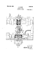
Figure 2, a horizontal section through the reversing gearing,
Figure 3, a vertical section on line 3-3, Figure 2, the parts being in working position.
Figure 4, a development of the main drivin shafts and associated parts,
Figure 5, an elevation o the work holder, and
Figure 6, a'detail of parts of a guard shown in Figure 1.
In the drawings reference character A indicates the fixed frame of a grinding machine, said frame being a closed casing aving the usual doors, bearings, etc. and also having superposed thereon a work holder B and a reciprocating carriage C for a inding wheel w.
A belt connected with a source of power (not shown) drives a pulley 11 fast to main This shaft has fast thereon two stepped pulleys 13 and 14.
A sleeve 15 is splined to shaft .12 and has a cone clutch member at each end adapted mo. Serial 80. 424,808.
to engage respectively with clutch members formed on sleeves 16 and 17 loose on shaft 12. Sleeves 16 and 17 have gear teeth 18 and 19 inte ral therewith respectively and both sets 0 teeth are in constant enga ement with a gear 20 on a shaft 21. T is shaft is mounted in a bearing 22 carried by lugs 23 and 24 on the frame of the machine. The hearing has a slot at one side through which a worm 25 engages with a worm wheel 26 on a vertical sha t 27 which drives wheel carriage C (Fig. 3) by means of a pinion 28 on the shaft in engagement with a rack 29 on the carriage. As the clutch sleeve 15 is shifted from side to side by means here inafter described the wheel carriage is moved back and forth on its track.
The fast pulleys 13 and 14 abut against the ends of sleeves 16 and 17 to hold them in place. A fast pulley 30 at the far end of the shaft drives a pump to rovide for the circulation of water, this being no part of mympresent invention.
A t 31 driven by pulley 13 passes over a step ed pulley 32 loose on a counter-shaft 33 an has integral therewith, or fixed thereto, a small pulley 34 which by means of belt 35 and ulley 36 drives shaft 37. This shaft has a c utch sleeve 38 splined thereto, said sleeve having oppositely projeetin teeth. Sleeves 39 and 40 loose on shaft 3 carry teeth adapted to engage alternately with those of the sleeve 38 and the also carry gear teeth 41 and 42 respective y which are in constant engagement with a gear 43, on shaft 21. A bushing 44 pinned to a bearing on the fixed frame ears at one end against gear 42 and at the other against a hand wheel 45 held in place by a ring-nut 46 threaded on sleeve 40. This hand wheel is intended for operatin the machine when the power is off. The ot er sleeve 39 is held in place by a collar 47 fixed to shaft 37 by a set-screw and having a flan e 48 engaging a groove in the collar. It wi l he noted that the belt caring provides for driving shaft 37 at a ow speed, and this is again decreased by gears 41, 42, and 43 to slow down shaft 21. The carriage C may thus be driv on either by hand or power at a low normal speed, or it may be driven at a high speed to move it out of and away from the work, high speed being attained when shaft 21 is driven by gear from gear 18 or 19.
Pulley 14 drives a stepped pulley by means of a belt 49, this pulley being loosely held on shaft 33 between two collars 51 and 52. At one end the pulley has a tapered surface forming a clutch member 53 to engage with a clutch member 53' on a sleeve 54. At the opposite end of the sleeve is a conical member 55 adapted to engage a braking surface 56 on a cylindrical member 57 located in an opening of the fixed frame and carrying a bearing for shaft 33. A spring 58 normally forces the clutch members into en agement.
he sleeve 54 has a shifter 59 on a shaft 60 actuated by a train of mechanism comprising a rock-arm 61, an elastic tension device 62, a link 63, and a lever 64 pivoted at 65 and having a roller at its free end for engagement by a cam 64 on the wheel carriage. Sleeve 54 is splined to shaft 33 and when clutch members 53, 53 are in engagement shaft 33 will be driven, thus drlving pulley 66, belt 67, pulley 68 and work-holder 69 in the form of a rotary spindle, which might be embodied in various forms and might have movements other than simple rotatlon, within the limits of my invention, which carries pulley 68 substantially in line with the axis on Wl'llCh the support is rotarily adjustable so as to maintain proper alignment of belt 68 and its pulleys. Contrariwise, cone 55 acts as a brake for the workholder and the train of gearing leading thereto.
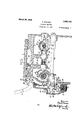
A clutch shifter 70 (Figs. 1 and 3) having a handle portion 71 is pivoted at 72 for movement toward and from the machine and is also movable laterally thereof on shaft 73 as a pivot, the enlargement at 72 sliding in a slot of the machine frame. A hood 74 formed on the handle 71 covers the slot to revent access of water and grit. Shaft 73 has a sleeve 73 concentric therewith for moving a clutch-fork 38 which controls reversing sleeve 38 and the lever 70 has a clutch sleeve 75 pivotally connected thereto at 76 in a fork at its lower end and slidable on shaft 73. A forked extension 70 of sleeve 75 carries a roller 76 cooperating with a yieldable detent 77 set in a casing A on the machine frame to hold the lever 70 in front or rear position. The spring 78 of the detent is introduced through an opening normally closed by a screw-plug 79. The casing A also has a door A for access to the lower end of lever 70 and adjacent parts.
With lever 70 in the position shown in Fi 3 the teeth of sleeve 75 engage sleeve 73 to operate reversing sleeve 38 as in the normal working of the machine with the wheel carriage reciprocating slowly. If the portion 71 of lever 70 is now forced the machine sleeve 75 will be unclutched from sleeve 73' and engaged with a clutch member 80 on shaft 73. Lateral movement of lever 70 will now rock shaft 73, clutch fork 81 and reversing sleeve 15. As lever 70 moves sleeve 75 out of en agement with sleeve 73', the extension 70 ra s a bar 82 with it. This bar slides in a gui e on the machine frame and is fixed at one end to extension 70 to move therewith and also extends through an opening of a downward extension 83 on sleeve 73'. This opening is preferably tapered to correspond to a tapered ortion of the bar and the sleeve is moved a central position and locked therein, thus locking the reversing sleeve 38 in central inactive position. Cluteh-fork 81 is similarly moved toward central position from one side by a yieldable abutment 81' on the frame, the shaft 73 and its clutch member 80 being moved to neutral position by dog 91) to stop the carriage and further movement being opposed by abutment 81.
he carriage C which is here shown as bearing the grinding wheel 10, but which may carry the work operated on, or an abrading device of different character, or other object, if desired, consists mainly of two parts, viz, a base C slidable lengthwise of the machine frame A, and a support C here shown as carrying the wheel and its driving devices, said support being adjustable transverse] of the base. The wheel w and its spind e 84 are driven at high speed in a direction opposite to that in which the work rotates, by a pulley on the spindle driven by a belt 85. A belt 86 connected to a source of power (not shown) drives pulley 87 which 1s on the same shaft with pulley 88 that drives belt 85. A dog ng device for lever 70 moves back and fort in time with the carriage being preferably rigidly fastened thereto, and comprises a rod 89 having rack teeth 89' on its under side and carrying a fixed abutment or dog 90 at one end. Dogs 91 and 92 are adjustable on the rod. each one having a worm 93 on a journal pivoted at one end to the dog and spring pressed toward the rack. By swinging the worm away from the rack a rough and quick adjustment may be made and thereafter an accurate adj ustment by turnin the worm. As the carriage reciprocates t e inner sides of dogs 91 and 92 strike against a spring-supported engaging lug 94 on lever 70 and move it to and fro to reverse whichever clutch-revers ing sleeve may be operative at the time. The dog 91 has a downward incline 95 to force the lug 94 back against the pressure of its spring as hereinafter described and is also cut away at the other side to form an inclined face 94'.
A guard or shield 96 is provided to keep the operator from touching wheel w and to handle toward ed as at 113 and provide protect him from flying cuttings, water and the like. -This guard is sup orted on a rod 97 slidable with respect to t e carriage C.
Rod 97 has a sleeve 98 slidable thereon at one end and the sleeve has spring fingers 99 for engagement with opposite sides of a stationary rod 100. Rod 100is supported on a bracket 101 fixed on the frame at 102. An abutment C is adapted to engage the opposite end of sleeve 98.
A second guard 103 is provided for the workholder 69 and this guard is pivoted at 104 for movement as b a handle 105'into the dash line sition an back to the full line sltlon w ere it completely covers the work. At its forward edge it has a boss having a bore 106 to hold a stub shaft 107. This stub shaft has a depending bracket 108 to receive a rod 109 clamped in place by screw 110 which su rts a device, e. g., for train the wheel. e stub shaft 107 isclamp d in position in the bore which is split for this purpose, by a screw 111 having a nut 112 and a handle 113 for operating the nut.
The base of the work-sup ort is calibratd with a hand wheel 114 for operating means such as worm-gearingl for turning the support a few degrees so t at the machine may operate on ta ering work and particularly on work that is internally tapered.
Operation.
The machine as a whole is started and stopped by means (not shown) operative to out off power from bolts 10 and 86, and which are not a part of m invention. As shown in the drawings, the belt 86 is driving the pulleys 87 and 88, spindle 84 and grindmg wheel 10 which is surrounded by shield 96. Belt 10 is driving shaft shaft 37 a through the train of parts 11 12 1:3,a1,32, s4, 35, and as. Sleeve 54 is held in position to disengage the clutch and opcrate the brake by the engagement of cam 64' with lever 64, and reversing sleeves 15 and 38 are in idle sition, the lever being ina position at t e limit of its movement (opposite of Figure 3) whereby bar 82 centers and locks the clutch shifter 74 and lever 70 is in its central position to which it has been moved by dog 90, its further movement being resiliently opposed by yieldin abutment 81.
Ano ject having been placed on the workholder e. g., a wheel with a tapering bearing to be internally ground, abutments 91 and 92 having been adjusted accordin to the length of the work, and the work-l iolder having been properly ad'usted on its pivot by operation of hand w eel 114, the shield 103 is placedin full-line position, and the operator moves lever 70 to the right (Fig. 1) to engage sleeve 15 with gear 19 and run the carriage up to the work at high speed.
12 and also P When abutment 95 engages the lever the operator moves it to its forward position (Fi 3) and the incline 94' en ages lug 94 to orce it down until the a utment has passed when the lug snaps back to position after which the abutments 91 and 92 strike the lug alternately at the end of each "rinding traverse to reverse the carriage during the low speed or feed drive.
As the cam 64' passes oil from lever 64, the clutch 53, 53' is thrown in and the work begins to revolve. Also the guard 96 is left in the position shown, being held b spring fingers 99 to rod 100, but abutment moves away from sleeve 98 with the carriage.
The guard 96 remains stationary until the spindle housing strikes against it, and then moves therewith, remaining in contact with the housing until the carriage moves so far toward inactive ositio'n that the fingers 99 contact with ro 100, and this in turn holds the guard stationary while the wheel approaches the guard 96. When abutment C strikes sleeve 98, the spring lingers .99 are forced into gripping relation with rod 100 while the wheel comes to position under the guard.
When the reciprocation of the carriage and the rotation of the work are to he stopped the operator swings lever 70 toward the machine, so clutching sleeve to shaft 7 3 and throwing the carriage on high speed for a quick traverse away from working osition.. i
The sleeve 38 being put in neutral position by bar 82 as lever 70 moves over, shaft 73 is at the same time moved so as to throw clutch-sleeve 15 to one side or the other, the teeth on sleeve 75 being so formed that they will engage those of the clutch member on shaft 7 3 and by a cam action move the shaft to cause engagement of one or the other friction clutch member by sleeve 15. The lever should always be operated for changing from low to high as the carriage moves to the right, but if it is moving to the left no harm will be done, as it will merely traverse rapidly to the left and then reverse and traverse rapidly to the right andaway from the work.
As the carriage travels to the right, the incline 95 will depress lug 94 and the travel will continue until the side of dog 90 strikes lug 94 when the lever 70 will be moved to its central position. At the same time cam 64 o crates lever 64 to actuate the clutch 53 and brake 55 to stop the work, and clutchshifter 81 comes to rest against stop 81'.
Hill
As the carriage C moves to inoperative position, guard 96 is carried along by the friction of the carriage'on rod 97 until fingers 99 strike rod 100 when the guard stands still until C strikes sleeve 98 forcing the fingers past rod 100 on opposite sides thereof and into holding engagement therewith, when the cvcle of movement is completed.
Various modified forms of my machine and its parts falling within the scope of my invention will occur to those skilled in the art, as well as adaptations of certain features for use in machines for other purposes. Therefore I do not limit myself to any particular embodiment 01' use of my machine or its component parts except; as indicated by the appended claims.
Having thus fully described my said invention, what I claim as new and desire to secure by Letters Patent, is:
1. In an abrading machine, a carriage, gearin to reciprocate thesame, a control lever or said gearing, a yieldable plug extending upward from said lever, dogs on the carriage adapted to engage the plug and swing the leverfroiii side to side, said lever being also swingable toward and from the carriage, and said dog having a beveledface adapted to ride over the plug in one position of the lever without moving the lever, substantially as set forth.
2. In a grinding machine, a reciprocatory carriage having an abrading device movable therewith, a rotary work-holder, means for giving the carriage an excessive movement in one direction, and means on the carriage operating on such excessive movement to stop the work-holder, substantially as set forth.
3. In a grinding machine, a reciprocatory carriage having an abrading device movable therewith, a rotary WOIk-lI0ld8l, fl reversing lever for the carriage, means on the carriage to move said lever to neutral position to stop the carriage, means for driving the \vorlcholder comprising a clutch, and a cam on the carriage for throwing out the clutch as the carriage comes to a stop, substantially as set forth.
4. In a grinding machine, a carriage, and reversing gearing for driving the carriage to and fro including a driven shaft, gears on said shaft, a pair of driving shafts, a pair of gearson each driving shaft engaging different gears on the driven shaft, meansfor clutching either one of each pair of gears to its shaft and selective means to render one pair of such gears inoperative, substantially as set forth.
5. In a grinding machinc, a work-holder and means for driving the same comprising a power shaft, :1 fast pulley thereon. a counter-shaft connected to the workholder, a loose pulley on the countershaft, a belt connecting said loose pulley to said fast pulmeans and means thereon for transmitting power from the driving to the driven shaft, substantially as set forth.
7. In a grinding machine, a carriage and means for driving the same, a lever for changing the speed and direction of motion of the carriage, dogging means on the carriage adapted to move the lever for reversing the movement of the carriage comprisin a dog adapted to pass the lever in one direction in its low-speed position, and in the opposite direction in its high-speed position, substantially as set forth.
8. In combination, a reciproeatory device, a lever to control the speed and direction of said device, means for reversing the lever and for placing it in neutral position to stop the reeipi'ocatory device, such means comprising a dog having the forward and rearward parts of one face oppositely beveled to permit the lever to pass it in opposite directions in its front and rear positions, substantially as set fort 9. In a grinding machine, a reciprocatory carriage, a, lever movable in one plane to change the direction of the carriage and i n another to alter its speed, dogging means to 10:; move it into reversing positions and also into neutral position to stop the carriage, said dogging means comprising a dog adapted to pass the lever in opposite directions in different positions of the lever, substantially no as set forth.
10. In a grinding machine, a reciprocatory carriage, a lever movable parallel thereto and also transversely thereof, a yieldable abutment on said lever, and a dog movable 115 with the carriage and having a beveled face to depress said abutment, during a movement in one direction and another beveled face to depress the abutment during a movement in the contrary direction, substantially at set forth.
11. In a grinding machine, a reciprocating carriage for an abrading device, said carlltl riage adapted to be withdrawn from the work, a guard for the abrading device adapt ed for movement with and with relation to the carriage, and means to bring the guard into operative relation as the carriage is withdrawn from the work, and to remove the guard from the abrading deviceas the moans latter approaches working position, substantially as set forth.
12. In a grindin machine, a reciprocating carriage for an a rading device, said carriage being adapted to be withdrawn from the work, a guard movable with the carriage, and means to hold the guard stationary durin a part of the withdrawing movement, substantially as set forth. 13. In a grinding machine, a carriage for an abrading device adapted to be moved into and out of working position and a guard for the abrading device having a lost motion connection with the carriage, substantially as set forth.
14. In combination, a movable carriage, a rotar shaft thereon, a device rotating with the s raft, a guard for said rotary device, and means for producing relative movement between the carriage and the guard whereby the guard is operative only in certain positions of the device, substantially as set forth.
15. In a grinding machine, a work-holder, a base therefor, means for adjusting the base about its center, a pulley mounted on the work-holder substantially at the center of rotation of said base, and a guard on the base between the work and the operator,
substantially as set forth.
16. In a grinding machine, an abrading device, a uard for the device when in active position, said device movable to idle position outside of said guard, and truing means for the abrading device carried by said guard and located adjacent to such idle position, substantially as set forth.
17. In a grindin machine, a work-holder, a rotarily adjustabIe base therefor, an abgadin device, a uard carried by said base and shielding sai abrading device when in active position, said device movable to idle position beyond said guard, a truing device carried by said guard adjacent an idle position of the abrading device, and adjustable on the uard to compensate for the adjustment of the base, substantially as set forth.
18. In a grinding machine, a work-holder and an abrading device having a relative rotary adjustment to position them for grinding surfaces at varyin angles, and a truing device adjacent sai abrading device, said truing device being adjustably mounted to compensate for said rotary adjustment, substantially as set forth.
19. In a grindin machine, a workholder, a. pivotally adjusta le base therefor, a wheel truing device carried by said workholder and adjustable about an axis at an angle to that of the base, substantially as set forth. 20. In a grindin machine, a workholder, a pivotally adjustable base therefor, a wheel truing device carried by said workholder and adjustable about an axis lying in a plane perpendicular to that of the base, substantial y as set forth.
21. In a grinding machine, a workholder adjustable about a vertical axis, a guard for the work mounted on said workholder and swinging on a horizontal axis into and out of operative position, and a wheel truing device carried by said guard and adjustable about a third axis at ri ht angles to each of said other axes, su stantially as set forth. a
22. In a grinding machine, a. workholder, a rotarily adjustable base therefor, an abruding device, a truing device for the abrading device pivoted on said base, and clamping means to fix the truing device in adjusted position, substantially as set forth.
In a grinding machine, an abrading device movable from idle to active position and vice versa, a guard for said de vice in active position, and an inde ndent guard therefor in idle position, su stantially as set forth.
24. In a grinding machine, an abrading device movable from idle to active position and vice versa, a guard for said device in active position, an independent guard therefor in idle position spaced from the first, and a truing device located between said "l1al4.ls and adapted to act on the abrading device in an idle position thereof, substantially as set forth.
2.). In a grinding machine, a workholder, a grinding wheel adapted to move into and out of operative. relation to the work, a guard for the wheel in operative position and an independent guard therefor in idle position, the latter guard having a lost motion connection to said grinding wheel, substantially as set forth.
'26. In a grinding machine, a workholder and means for driving the same comprising a power shaft, a fast pulley thereon, a countershaft connected to the workholder, a loose pulley on the counter-shaft, a belt connecting said loose pulley to said fast pulley, a clutch member splined to said shaft and adapted to engage and be driven by said loose pulley, a shifter for said clutch, a reciprocating carriage for an abrading device, and means on the carriage to operate said shipper to disengage said clutch, substantially as set forth.
27. In a grinding machine, a workholding device, an abrading device, a carriage for one of said devices adapted-to be moved into and out of operative relation, and a guard automatically movable to shield said device as the carriage moves outof such operative relation, substantially asset forth.
28. In an abrading machine, a carriage and means to reciprocate the same comprising means to move the carriage at working speed in working position, automatic means to move it at higher speed away from the change-speed gearing to said lever 10 from working position and means to stop for changing the speed of the carriage by it. in working position, substantially as set movement 0 the lever in a plane singularly forth. related to the first, substantially as set forth.
5 2.). In an abrnding machine, a carriage, In witness whereof, I have hereunto set means to more the carriage to-anrl-fro inmy hand at Washington, District of Co- 15 rlmlin; reversible gearing. a reversing lever lumbia this thirteenth (lay of November, A. lllvl'cfor oscillating in a plane, change-speed D. nineteen hundred and twenty.
gearing for the carriage, and connections PAUL STONER.
CERT] F I GATE 0F (10R REGTION.
Patent No. 1,663,148. March 20, 1928.
PAUL STONER.
It is hereby certified that error appears in the printed specification of the above numbered patent requiring correction as follows: Page 6, lines 2 and 3, claim 28, strike out the words "means to stop it in working position" and insert instead "manual controlling means for such automatic means"; and that the said Letters Patent should he read with this correction therein that the same may conform to the record of the case in the Patent Office.
Signed and sealed this 7th day of February, A. 1). I933.
M. J. .Vloore, (Seal) Acting Commissioner of Patents.
means to move it at higher speed away from the change-speed gearing to said lever 10 from working position and means to stop for changing the speed of the carriage by it. in working position, substantially as set movement 0 the lever in a plane singularly forth. related to the first, substantially as set forth.
5 2.). In an abrnding machine, a carriage, In witness whereof, I have hereunto set means to more the carriage to-anrl-fro inmy hand at Washington, District of Co- 15 rlmlin; reversible gearing. a reversing lever lumbia this thirteenth (lay of November, A. lllvl'cfor oscillating in a plane, change-speed D. nineteen hundred and twenty.
gearing for the carriage, and connections PAUL STONER.
CERT] F I GATE 0F (10R REGTION.
Patent No. 1,663,148. March 20, 1928.
PAUL STONER.
It is hereby certified that error appears in the printed specification of the above numbered patent requiring correction as follows: Page 6, lines 2 and 3, claim 28, strike out the words "means to stop it in working position" and insert instead "manual controlling means for such automatic means"; and that the said Letters Patent should he read with this correction therein that the same may conform to the record of the case in the Patent Office.
Signed and sealed this 7th day of February, A. 1). I933.
M. J. .Vloore, (Seal) Acting Commissioner of Patents.
Priority Applications (1)
| Application Number | Priority Date | Filing Date | Title |
|---|---|---|---|
| US424898A US1663148A (en) | 1920-11-18 | 1920-11-18 | Grinding machine |
Applications Claiming Priority (1)
| Application Number | Priority Date | Filing Date | Title |
|---|---|---|---|
| US424898A US1663148A (en) | 1920-11-18 | 1920-11-18 | Grinding machine |
Publications (1)
| Publication Number | Publication Date |
|---|---|
| US1663148A true US1663148A (en) | 1928-03-20 |
Family
ID=23684326
Family Applications (1)
| Application Number | Title | Priority Date | Filing Date |
|---|---|---|---|
| US424898A Expired - Lifetime US1663148A (en) | 1920-11-18 | 1920-11-18 | Grinding machine |
Country Status (1)
| Country | Link |
|---|---|
| US (1) | US1663148A (en) |
-
1920
- 1920-11-18 US US424898A patent/US1663148A/en not_active Expired - Lifetime
Similar Documents
| Publication | Publication Date | Title |
|---|---|---|
| US1379853A (en) | Method of eoemiwg cutting-tools | |
| US1663148A (en) | Grinding machine | |
| US3788170A (en) | Mechanism for radial adjustment of tools in rotary tubular tool holders of shaving machines or the like | |
| US1243241A (en) | Platen-grinding machine. | |
| US1584717A (en) | Grinding-wheel-spindle-reciprocating mechanism | |
| US1522465A (en) | Internal-grinding machine | |
| US2010361A (en) | Grinding machine | |
| US2025885A (en) | Grinding machine | |
| US2395910A (en) | Machine and method for grinding hobs and the like | |
| US1395391A (en) | Device for truing and dressing grinding-wheels | |
| US1924593A (en) | Grinding machine | |
| US1624868A (en) | Metal-working machine | |
| US483288A (en) | Grinding-machine | |
| US1861497A (en) | Hydraulic table feed mechanism | |
| US2058940A (en) | Metal cutting machine | |
| US1705749A (en) | Internal grinder | |
| US1982298A (en) | Grinding machine | |
| US2000216A (en) | Grinding machine | |
| US1036544A (en) | Grinding-machine. | |
| US2367593A (en) | Machine tool | |
| USRE16196E (en) | A cobpobation | |
| US1416054A (en) | Cross-feed mechanism for machine tools | |
| US1624211A (en) | Multispindle internal-combustion machine | |
| US1982297A (en) | Grinding machine | |
| US2263928A (en) | Milling machine |