US1663137A - Electric spot-welding machine - Google Patents
Electric spot-welding machine Download PDFInfo
- Publication number
- US1663137A US1663137A US10512A US1051225A US1663137A US 1663137 A US1663137 A US 1663137A US 10512 A US10512 A US 10512A US 1051225 A US1051225 A US 1051225A US 1663137 A US1663137 A US 1663137A
- Authority
- US
- United States
- Prior art keywords
- arm
- transformer
- cup
- cups
- machine
- Prior art date
- Legal status (The legal status is an assumption and is not a legal conclusion. Google has not performed a legal analysis and makes no representation as to the accuracy of the status listed.)
- Expired - Lifetime
Links
- 238000003466 welding Methods 0.000 title description 19
- 238000004804 winding Methods 0.000 description 22
- 238000003475 lamination Methods 0.000 description 8
- 238000010276 construction Methods 0.000 description 7
- 230000004048 modification Effects 0.000 description 4
- 238000012986 modification Methods 0.000 description 4
- 239000004020 conductor Substances 0.000 description 2
- NJPPVKZQTLUDBO-UHFFFAOYSA-N novaluron Chemical compound C1=C(Cl)C(OC(F)(F)C(OC(F)(F)F)F)=CC=C1NC(=O)NC(=O)C1=C(F)C=CC=C1F NJPPVKZQTLUDBO-UHFFFAOYSA-N 0.000 description 2
- 238000005266 casting Methods 0.000 description 1
- 230000008676 import Effects 0.000 description 1
- 238000007689 inspection Methods 0.000 description 1
- 238000004519 manufacturing process Methods 0.000 description 1
- 239000000463 material Substances 0.000 description 1
- 238000000034 method Methods 0.000 description 1
- 238000003825 pressing Methods 0.000 description 1
- 230000008569 process Effects 0.000 description 1
- 230000009467 reduction Effects 0.000 description 1
Images

Classifications
-
- B—PERFORMING OPERATIONS; TRANSPORTING
- B23—MACHINE TOOLS; METAL-WORKING NOT OTHERWISE PROVIDED FOR
- B23K—SOLDERING OR UNSOLDERING; WELDING; CLADDING OR PLATING BY SOLDERING OR WELDING; CUTTING BY APPLYING HEAT LOCALLY, e.g. FLAME CUTTING; WORKING BY LASER BEAM
- B23K11/00—Resistance welding; Severing by resistance heating
- B23K11/24—Electric supply or control circuits therefor
Definitions
- My invention relates to electric welding machines of the resistance type wherein the one electrode or pole of the secondary winding is movable for the purpose of pressing the blank, and more particularly to a machine of the spot-welding or blunt edge or end welding character.
- the main object of my invention is to provide a machine of the stated kind which will be of simple construction thereby saving material and reducing the cost of manufacture while at the same time the weight of the machine will be reduced and a more compact structure will be obtained.
- Another feature of my invention resides in constructing and arranging the secondary winding to form two half-casin s or cups adapted to be displaced relative y to one another and to enclose the primary winding and the laminated sheet pack of the transformer, the one half-casing bein provided with a bearing pin, the other hal casing being equipped with a corresponding sleeve so that by having the pin engaged in the sleeve the two half-casings will be assembled to constitute in their totality a casing comprisin two halves which can be displaced at wilI about the common axis or pin.
- Both the pin and the sleeve co-operating therewith may be made integral with their half-casings respectively.
- a still further feature of my invention lies in rigidly connecting or integrating certain outer conducting means, such as the electrode arms, with the two casings, the said electrode arms servin at the same time to import a pressure to t e work in order to bring the welding surface into suflicient- It will thus be seen Furthermore, in some cases I modify the construction of the machine by locating and arranging the movable welding arm carrying the one secondary electrode, in the middle of the machine, i. e. intermediate between the two half-casings or cups. In this modification the two half-casings or cups are adapted to receive each a part. transformer and may be stationary or immovable themselves. Also such a modification affords all and any of the advantages aforestated.
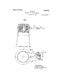
- Figure 1 shows diagrammatically in side elevation, a spotwelding machine constructed according to my invention
- Figure 2 is a horizontal section taken on the line 2-2 of Figure 1 showing that the machine comprises a single transformer only;
- Figure 3 is a similar sectional view of a like machine comprising two transformers
- Figure t is a vertical section of a machine according to my invention for bluntedge or end welding purposes and Figure 5 is a plan of the latter.
- the two cup-shaped casings a and b constitute, if assembled as shown, the casing of the'transformer and the secondary conductors.
- a pin 0 projects horizontally and a sleeve 0 projects horizontally from the bottom of the cup a said sleeve being adapted to snugly fit on the pin a when the parts are assembled as shown.
- the laminations d of the transformer are mounted to surround the sleeve 0.
- the primary winding of the transformer is indicated at e.
- the one cup or half-casing, sa a is duly supported by a pedestal a.
- T e free endof the pin 0 projects a little beyond the outer bottom face of the cup a to receive a washer and a nut j for securing the two cups a and b in assembled position while at the same time allowing the cup I) to be rotated or oscillated with relation to the sta tionary cup a.
- Each cup is firmly connected with an electrode arm ,7 or f respectively.
- the two arms f and f are formed integral with the respective cup by casting.
- the arm f and cup 6 has another arm or bracket 9 which likewise may be cast integral therewith.
- a lever 73 fulcrumed at a point a" of the pedestal a is connected with the arm or bracket 9 by means of a link it. -By pulling the free end of the lever i downwards, as indicated in Figure 1 by an arrow, the electrode arm f will be lowered to approach the stationary electrode arms f and the two electrodes 8 and .9 carried by the two arms will also approach each other until they come in contact with the work m, as shown in Figure 1.
- the transformer is divided to form two separate parts and the upper electrodes arm 7 is mounted midway between the two sets of laminations OZ.
- the lower arm f is rigidly connected or. integral with the divided casing k which is always at rest or, in other words, does not partake, neither totally nor partially, in the'movements of the arm 1.
- Two studs t and 23 project from'opposed inner walls of the casingand the inner free ends of the two studs are bored to form bearing seats for the journals or pins 0 of the arm f.
- the two studs 2), t are cast in one with the halves of the casing and penetrate into or project through the laminated sheet packs (1 of the parts of the transformer.
- the arm is duly iournalled in the two studs and a a ted to swing about the axis of the studs, w on the arm Z which is identical, as regards its function, with the arm 9 shown in Figures 1 and 2, is moved up or down, preferably with the aid'of means similar to those shown in Figure l'for the purpose.
- the casing serves as a secondary winding, while the primary windings are indicated at e in Figure 3.
- the two work pieces n and n to be welded together are firmly secured by clamping -or any other appropriate means in the free ends of the two electrode arms 7' and f respectively, as will be readily understood from an inspection of Figure 5 wherein the two arrows indicate the directions of the movement of the two arms 7*, 7" towards one another.
- the means for moving the arm 7 comprise a lateral bracket or arm 9 rigidly connected or integral with the arm 7, a hand lever 39 fulcrumed in the arm q and a link 1' pivotally attached to the lever p and to the stationary arm 7".
- the movable arm f has a transverse bore which is 'wide enough for the link to pass therethrough without touching the sides of said bore and consequently with no friction.
- the movable parts adopt the positions shown in Figure 5 in dotted lines, but when two work pieces 'n and n are properly inserted and fixed in the two arm, f and f in order to be united by the welding process, the hand lever p is to be moved by the operator into the position shown in full lines whereby the movable arm 7 is likewise moved ulcerotheposition shown in full lines and the work piece it is brought into blunt end contact with the other piece n.
- the contact of the work pieces .11, and n issufliciently intimate owing'to the pressure exer .cised by the operator on the hand lever a homogeneous weld between'the two bodies of the. work operated upon is produced and the two bodies become integrally one body.
- Electric welding machine comprising a transformer with a primary and a secondary winding, a stationary electrode arm, a movable electrode arm adapted to be moved toward and away from the stationary electrode arm, and a central member surrounded by the laminations of the said transformer, the said movable electrode arm in the least departing from the nature and bein pivotally supported by said central mem er.
- Electric welding machine comprising a transformer with a primary and a secondary winding, two cups movable relatively to each other and enclosing'the primary winding and the laminations of the said transformer, said cups forming the secondary winding of the transformer.
- Electric welding machine comprising a transformer witha primary and a secondary winding, two cups movable relatively to each other and enclosing the primary winding and the laminations of the said transformer, a bearing pin rigidly and conductively connected wit the one cup, and a bearing sleeve rigidly and conductively connected with the other cup and co-operating with the said pin, said cups with said pin and sleeve forming the secondary winding of the transformer, each cup being rigidly connected with one electrode arm.
- Electric welding machine comprising a transformer with a primary and a secondary winding, two cups rockable relatively to each other and enclosing the primary wind.- ing and the laminations of the said transformer, a bearing pin rigidly and conductively connected with the one of the said two cups, a bearing sleeve rigidly and conductively connected with the other cup and cooperating with the said fpin as a layer for the rocking movement 0 one of the two cups, a stationary electrode arm rigidly connected with the stationary cup and a movable electrode arm rigidly connected with the rockable cup, said cups with said pin and sleeve and electrode .arms forming the secondary winding.
- Electric welding machine comprising a transformer with a primary and a secondary winding, two cups rockable relatively to each other and enclosing the primar winding and the laminations of the sai transformer a bearing pin rigidly and conductively connected with the one of the said two cups, a bearing sleeve rigidly and conductively connected with the other cup and cooperating with the said pin a pivotal connection for the rocking movement of one of the two cups, a stationary electrode arm rigidly connected with the stationary cup and a .movable electrode arm rigidly connected with the rockable cup, said cups with said pin and sleeve and electrode arms forming the secondary winding and an arm fastened to the movable cup and operable by a suitable leverage.
- Electric welding machine comprising a transformer with a primary and a second ary winding, two cups rockable relatively to each other and enclosing the primary winding and the laminations of the said transformer a bearing pin rigidly and conductively connected with the one of the said two cups, a bearing sleeve rigidly and conductively connected with the other cup and cooperating with the said pin a pivotal connection for the rocking movement of one of the two cups, a stationary electrode arm rigidly connected with the stationary cup and a movable electrode arm rigidly connected with the rockable cup, said cups with said pin and sleeve and electrode arms forming the secondary Winding, the electrode arms being operatively connected with each other by a suitable leverage.
Landscapes
- Engineering & Computer Science (AREA)
- Mechanical Engineering (AREA)
- Resistance Welding (AREA)
Description
\ 2 Sheets-Sheet 1 R. MACK ELECTRIC SPOT WELDING MACHINE Filed Feb. 20, 1925 March 20, 1928.
I I u u u I Afforne 5 s March 20, 1928.
Filed Feb, 20, 1925 2 Sheets-Sheet 2 HQW o n 1 r m r Patented Mar. 20, UNITED STATES PATENT OFFICE.
RICHARD MACK, OF BERLIN-TEMPELHOF, GERMAN-Y.
ELECTRIC SPOT-WELDING MACHINE.
Application filed February 20, 1925, Serial No. 10,512, and in Germany February.28, 1924.
My invention relates to electric welding machines of the resistance type wherein the one electrode or pole of the secondary winding is movable for the purpose of pressing the blank, and more particularly to a machine of the spot-welding or blunt edge or end welding character.
The main object of my invention is to provide a machine of the stated kind which will be of simple construction thereby saving material and reducing the cost of manufacture while at the same time the weight of the machine will be reduced and a more compact structure will be obtained.'
,IVith this object in view I construct and arrange the portion of the secondary winding surrounded or enclosed by the pack of laminated sheets of the transformer, to con-- stitute a sliding or rocking bearing for the movable part of the secondary conductor which, as above stated, is utilized for pressin}; the blank. In this way I mount the bearing within the transformer Whereas in machines hitherto constructed or suggested the bearing is mounted on the top of the transformer casing. that owing to my improved construction the height or vertical extension of the machine is considerably reduced.
Another feature of my invention resides in constructing and arranging the secondary winding to form two half-casin s or cups adapted to be displaced relative y to one another and to enclose the primary winding and the laminated sheet pack of the transformer, the one half-casing bein provided with a bearing pin, the other hal casing being equipped with a corresponding sleeve so that by having the pin engaged in the sleeve the two half-casings will be assembled to constitute in their totality a casing comprisin two halves which can be displaced at wilI about the common axis or pin. In this way I ensure a further reduction of the size of the machine so as to obtain a small machine of highly compact construction Both the pin and the sleeve co-operating therewith may be made integral with their half-casings respectively. A still further feature of my invention lies in rigidly connecting or integrating certain outer conducting means, such as the electrode arms, with the two casings, the said electrode arms servin at the same time to import a pressure to t e work in order to bring the welding surface into suflicient- It will thus be seen Furthermore, in some cases I modify the construction of the machine by locating and arranging the movable welding arm carrying the one secondary electrode, in the middle of the machine, i. e. intermediate between the two half-casings or cups. In this modification the two half-casings or cups are adapted to receive each a part. transformer and may be stationary or immovable themselves. Also such a modification affords all and any of the advantages aforestated.
With the above recited objects or features in View the invention resides in the novel construction set forth in the following specification, particularly pointed out in the appended claims and illustrated in the accompanying drawings, it being understood that the right is reserved to embodiments other than those illustrated herein to the full extent indicated by the general meaning of the terms in which the claims are expressed.
In the. accompanying drawings forming a part of this specification Figure 1 shows diagrammatically in side elevation, a spotwelding machine constructed according to my invention;
Figure 2 is a horizontal section taken on the line 2-2 of Figure 1 showing that the machine comprises a single transformer only;
Figure 3 is a similar sectional view of a like machine comprising two transformers;
Figure t is a vertical section of a machine according to my invention for bluntedge or end welding purposes and Figure 5 is a plan of the latter.
Referring to the embodiment shown in Figures 1 and 2 the two cup-shaped casings a and b constitute, if assembled as shown, the casing of the'transformer and the secondary conductors. From the bottom of the cup 6 a pin 0 projects horizontally and a sleeve 0 projects horizontally from the bottom of the cup a said sleeve being adapted to snugly fit on the pin a when the parts are assembled as shown. The laminations d of the transformer are mounted to surround the sleeve 0. The primary winding of the transformer is indicated at e. The one cup or half-casing, sa a, is duly supported by a pedestal a. T e free endof the pin 0 projects a little beyond the outer bottom face of the cup a to receive a washer and a nut j for securing the two cups a and b in assembled position while at the same time allowing the cup I) to be rotated or oscillated with relation to the sta tionary cup a.
Each cup is firmly connected with an electrode arm ,7 or f respectively. In the embodiment shown in Figures 1 and 2 the two arms f and f are formed integral with the respective cup by casting. in opposite direction to the arm f and cup 6 has another arm or bracket 9 which likewise may be cast integral therewith. A lever 73 fulcrumed at a point a" of the pedestal a is connected with the arm or bracket 9 by means of a link it. -By pulling the free end of the lever i downwards, as indicated in Figure 1 by an arrow, the electrode arm f will be lowered to approach the stationary electrode arms f and the two electrodes 8 and .9 carried by the two arms will also approach each other until they come in contact with the work m, as shown in Figure 1. By thus pulling the lever 2' down the two electrodes are caused to exercise a powerful grip on the work at the welding spot, while at the same time the welding operation is edected. By raising the lever 2' in opposite direction to that indicated by the arrow the two arms f and f and the electrodes 8 and s are separated and recede from each other to receive a blank for a next welding operation.
In the embodiment illustrated in Figure 3 the transformer is divided to form two separate parts and the upper electrodes arm 7 is mounted midway between the two sets of laminations OZ. The lower arm f is rigidly connected or. integral with the divided casing k which is always at rest or, in other words, does not partake, neither totally nor partially, in the'movements of the arm 1. Two studs t and 23 project from'opposed inner walls of the casingand the inner free ends of the two studs are bored to form bearing seats for the journals or pins 0 of the arm f. The two studs 2), t are cast in one with the halves of the casing and penetrate into or project through the laminated sheet packs (1 of the parts of the transformer. In this manner the arm is duly iournalled in the two studs and a a ted to swing about the axis of the studs, w on the arm Z which is identical, as regards its function, with the arm 9 shown in Figures 1 and 2, is moved up or down, preferably with the aid'of means similar to those shown in Figure l'for the purpose. Also in the embodiinent illustrated in Figure 3 the casing serves as a secondary winding, while the primary windings are indicated at e in Figure 3.
In the modification, shown in Figures 4 and 5 the princi 1e of construction is the This arrangement renders the machine particularly fit for blunt edge or end-welding purposes.
In this modification the two work pieces n and n to be welded together are firmly secured by clamping -or any other appropriate means in the free ends of the two electrode arms 7' and f respectively, as will be readily understood from an inspection of Figure 5 wherein the two arrows indicate the directions of the movement of the two arms 7*, 7" towards one another. The means for moving the arm 7 comprise a lateral bracket or arm 9 rigidly connected or integral with the arm 7, a hand lever 39 fulcrumed in the arm q and a link 1' pivotally attached to the lever p and to the stationary arm 7". The movable arm f has a transverse bore which is 'wide enough for the link to pass therethrough without touching the sides of said bore and consequently with no friction. Normally the movable parts adopt the positions shown in Figure 5 in dotted lines, but when two work pieces 'n and n are properly inserted and fixed in the two arm, f and f in order to be united by the welding process, the hand lever p is to be moved by the operator into the position shown in full lines whereby the movable arm 7 is likewise moved iritotheposition shown in full lines and the work piece it is brought into blunt end contact with the other piece n. As soon as the contact of the work pieces .11, and n issufliciently intimate owing'to the pressure exer .cised by the operator on the hand lever a homogeneous weld between'the two bodies of the. work operated upon is produced and the two bodies become integrally one body.
I am aware that minor changes in the arrangement, construction, and combination of the several parts of my improved machine" or device can be made and substituted for those herein shown and described Without principle of my invention.
I What I claim is 1. Electric welding machine, comprising a transformer with a primary and a secondary winding, a stationary electrode arm, a movable electrode arm adapted to be moved toward and away from the stationary electrode arm, and a central member surrounded by the laminations of the said transformer, the said movable electrode arm in the least departing from the nature and bein pivotally supported by said central mem er.
2. Electric welding machine, comprising a transformer with a primary and a secondary winding, two cups movable relatively to each other and enclosing'the primary winding and the laminations of the said transformer, said cups forming the secondary winding of the transformer.
3. Electric welding machine, comprising a transformer witha primary and a secondary winding, two cups movable relatively to each other and enclosing the primary winding and the laminations of the said transformer, a bearing pin rigidly and conductively connected wit the one cup, and a bearing sleeve rigidly and conductively connected with the other cup and co-operating with the said pin, said cups with said pin and sleeve forming the secondary winding of the transformer, each cup being rigidly connected with one electrode arm.
4. Electric welding machine, comprising a transformer with a primary and a secondary winding, two cups rockable relatively to each other and enclosing the primary wind.- ing and the laminations of the said transformer, a bearing pin rigidly and conductively connected with the one of the said two cups, a bearing sleeve rigidly and conductively connected with the other cup and cooperating with the said fpin as a layer for the rocking movement 0 one of the two cups, a stationary electrode arm rigidly connected with the stationary cup and a movable electrode arm rigidly connected with the rockable cup, said cups with said pin and sleeve and electrode .arms forming the secondary winding.
5. Electric welding machine, comprising a transformer with a primary and a secondary winding, two cups rockable relatively to each other and enclosing the primar winding and the laminations of the sai transformer a bearing pin rigidly and conductively connected with the one of the said two cups, a bearing sleeve rigidly and conductively connected with the other cup and cooperating with the said pin a pivotal connection for the rocking movement of one of the two cups, a stationary electrode arm rigidly connected with the stationary cup and a .movable electrode arm rigidly connected with the rockable cup, said cups with said pin and sleeve and electrode arms forming the secondary winding and an arm fastened to the movable cup and operable by a suitable leverage.
6. Electric welding machine, comprising a transformer with a primary and a second ary winding, two cups rockable relatively to each other and enclosing the primary winding and the laminations of the said transformer a bearing pin rigidly and conductively connected with the one of the said two cups, a bearing sleeve rigidly and conductively connected with the other cup and cooperating with the said pin a pivotal connection for the rocking movement of one of the two cups, a stationary electrode arm rigidly connected with the stationary cup and a movable electrode arm rigidly connected with the rockable cup, said cups with said pin and sleeve and electrode arms forming the secondary Winding, the electrode arms being operatively connected with each other by a suitable leverage.
In testimony whereof I have signed my name to this specification.
RICHARD MACK.
Applications Claiming Priority (1)
| Application Number | Priority Date | Filing Date | Title |
|---|---|---|---|
| DE1663137X | 1924-02-28 |
Publications (1)
| Publication Number | Publication Date |
|---|---|
| US1663137A true US1663137A (en) | 1928-03-20 |
Family
ID=7738622
Family Applications (1)
| Application Number | Title | Priority Date | Filing Date |
|---|---|---|---|
| US10512A Expired - Lifetime US1663137A (en) | 1924-02-28 | 1925-02-20 | Electric spot-welding machine |
Country Status (1)
| Country | Link |
|---|---|
| US (1) | US1663137A (en) |
Cited By (2)
| Publication number | Priority date | Publication date | Assignee | Title |
|---|---|---|---|---|
| US2678367A (en) * | 1949-08-27 | 1954-05-11 | M & S Maschinen Und Stahl A G | Electric resistance welding machine for spot or seam welding |
| US4525618A (en) * | 1983-10-26 | 1985-06-25 | Beneteau Donald J | Resistance welding apparatus |
-
1925
- 1925-02-20 US US10512A patent/US1663137A/en not_active Expired - Lifetime
Cited By (2)
| Publication number | Priority date | Publication date | Assignee | Title |
|---|---|---|---|---|
| US2678367A (en) * | 1949-08-27 | 1954-05-11 | M & S Maschinen Und Stahl A G | Electric resistance welding machine for spot or seam welding |
| US4525618A (en) * | 1983-10-26 | 1985-06-25 | Beneteau Donald J | Resistance welding apparatus |
Similar Documents
| Publication | Publication Date | Title |
|---|---|---|
| US1663137A (en) | Electric spot-welding machine | |
| US1536838A (en) | Spot-welding machine | |
| US1986512A (en) | Miniature welding machine | |
| US1086041A (en) | Welding-machine. | |
| US2465879A (en) | Portable spot welder | |
| US2788403A (en) | Electrical isolating switches | |
| JPH049100Y2 (en) | ||
| JPH087979Y2 (en) | Welding machine uniform pressure device | |
| US3054887A (en) | Welding fixture | |
| CN221754951U (en) | A soldering machine with positioning function | |
| US1333722A (en) | Electric sadiron | |
| US2410691A (en) | Electrical connector | |
| GB230093A (en) | Improvements in or relating to electric welding machines | |
| DE619808C (en) | Multi-part electric double or multi-point welding machine with adjacent electrodes | |
| CN218676965U (en) | Magnetic conductive combined DC contactor | |
| US2033616A (en) | Welding machine | |
| US1890933A (en) | Foundry molding machine of roll-over type | |
| US2693519A (en) | Circuit interrupter | |
| US922795A (en) | Cutting-off apparatus. | |
| JPH0468334U (en) | ||
| US1852139A (en) | Electrically operated switch closing mechanism | |
| DE414863C (en) | Electric welding and heating machine | |
| US1318508A (en) | simon | |
| US1075209A (en) | Welding-machine. | |
| US1798309A (en) | Four-roll hammer |