US1663131A - Scaffold - Google Patents
Scaffold Download PDFInfo
- Publication number
- US1663131A US1663131A US170542A US17054227A US1663131A US 1663131 A US1663131 A US 1663131A US 170542 A US170542 A US 170542A US 17054227 A US17054227 A US 17054227A US 1663131 A US1663131 A US 1663131A
- Authority
- US
- United States
- Prior art keywords
- putlog
- scaffold
- platform
- support
- edge
- Prior art date
- Legal status (The legal status is an assumption and is not a legal conclusion. Google has not performed a legal analysis and makes no representation as to the accuracy of the status listed.)
- Expired - Lifetime
Links
- 238000010276 construction Methods 0.000 description 4
- 241000220284 Crassulaceae Species 0.000 description 1
Images
Classifications
-
- E—FIXED CONSTRUCTIONS
- E04—BUILDING
- E04G—SCAFFOLDING; FORMS; SHUTTERING; BUILDING IMPLEMENTS OR AIDS, OR THEIR USE; HANDLING BUILDING MATERIALS ON THE SITE; REPAIRING, BREAKING-UP OR OTHER WORK ON EXISTING BUILDINGS
- E04G3/00—Scaffolds essentially supported by building constructions, e.g. adjustable in height
- E04G3/28—Mobile scaffolds; Scaffolds with mobile platforms
- E04G3/30—Mobile scaffolds; Scaffolds with mobile platforms suspended by flexible supporting elements, e.g. cables
- E04G3/32—Hoisting devices; Safety devices
Definitions
- the present invention relates to scaffolds, and more particularly to means for manually raising and lowering the scaffold and securing the same in adjusted position.
- An object of the present invention is to provide a simple and easily attached mechanism capable of manual operation of raising and lowering the platform and for holding the platform in its adjusted position, so that the platform may be stepped up or down according to the desired adjustment.
- Another object of the invention is to pro vide a manually operable device of this character which may be easily handled and which may be used in multiple, such as one at each corner of the scaffold, so that the scaffold platform may be stepped up or adjusted at difierent points.
- Figure 1 is a perspective view of the scaffold suspended and supported according to the present invention.
- Figure 2 is a detail enlarged side elevation of one of the manually operable adjusting devices as applied to the scaffold and one of the supports therefor.
- Figure 3 is a fragmentary detail view of thelower portion of Figure 2, showing a modified construction of adjustable support for the putlog of the scaffold.
- Figure 4 is a fragmentary top plan view of the device as shown in Figure 2, and
- Figure 5 is a fragmentary enlarged side elevation of an automatic locking device between the putlog and the supporting memher for automatically locking the putlog in adjusted position.
- 10 designates a platform of a scaffold which may be 0011- structed in the usual manner of a plurality of boards arranged lengthwise and in edge contact with each other across putlogs 11 arranged at the ends of the platform.
- the putlogs 11 may be of any desired construction and may be made of spaced beams of the conventional size which are of suflicient length to extend beyond the inner and outer edges of the platform 10, and which are adapted to receive between their opposite ends the vertical straps or other supports 12. which are suspended from Outriggers 13 or the like which project outwardly from the upper edge of a wall 14.
- the straps or supports 12 are four in number according to the present illustration and are provided at suitably spaced intervals with transverse apertures 15 extending therethrough'and of sufi'icient size to receive each a removable pin 16 which engages the lower edge of the putlog'll to support it from sliding downwardly upon the strap 12, and to thus support the platform 10.
- Each putlog 11 is provided at its outer end with a link 17 which is mounted upon a pivot 18 permanently upon the putlog, if desired, so that the links 17 will always be in position to engage a hook 19 carried upon the lower end of a link 20 which in turn is pivotally connected by a bolt or rivet 21 to the end of an operating lever 22.
- the operating lever 22 may be of forked construction so as to straddle or engage about the strap 12, and the intermediate portion of the lever 22 is apertured to receive a quickly detachable bolt 23 adapted to pivot the lever 22 to the support 12 at different points by engagement of the bolt 23 injthe selected open-v ings 15.
- the lever 22 may have its inner or handle end socketed to detachably receive therein 9 the end of a handle 24.
- the handle 24 may be of suitable length so as to be grasped by the person operating the device and so that suflicient leverage may be obtained for drawing up the link 20 and lifting the adjacent end of the putlog 11.
- a stirrup 25 may be employed for engaging about and beneath the adjacent end of the putlog 11 and supported at its upper end by a removable bolt orpin 26 which is engaged in the selected openings 15 of the support.
- the adjustable pin ,26 is in a position of more easy access than are inclined inwardly and downwardly from the edge of the support 12.
- the putlog 11 carries a link or loop 28 pivoted to the putlog at 29 and urged at its outer end by a spring 30 against the edge of the support 12 so that the loop 28 swings into the notches .27 when the putlog 11 is raised sufliciently to bring the free end of the link into register with the notches.
- the act of lifting the putlog 11 first releases the loop 28 from its notch and the edge of the support 12 holds the loop 28 from interlocked position until the next higher notch 27 is reached.
Landscapes
- Engineering & Computer Science (AREA)
- Architecture (AREA)
- Mechanical Engineering (AREA)
- Civil Engineering (AREA)
- Structural Engineering (AREA)
- Apparatus Associated With Microorganisms And Enzymes (AREA)
Description
March 20, 1928. I 1,663,131 I F. B. JOHNSTON v SCAFFOLD' Filed Feb. 24, 1927 22 EE 10 E Patented Mar. 26, 1228.
innran srarss SAFETY DEvlCiE'CoMPANY OF'NEW YQRK, N. Y.', A. CORPORATION NET/V YORK.
scAFroti);
Application-filed February a l, i927. Serial No. 170,542;
The present invention relates to scaffolds, and more particularly to means for manually raising and lowering the scaffold and securing the same in adjusted position.
An object of the present invention is to provide a simple and easily attached mechanism capable of manual operation of raising and lowering the platform and for holding the platform in its adjusted position, so that the platform may be stepped up or down according to the desired adjustment.
Another object of the invention is to pro vide a manually operable device of this character which may be easily handled and which may be used in multiple, such as one at each corner of the scaffold, so that the scaffold platform may be stepped up or adjusted at difierent points.
WVith the foregoing and other objects in view, the invention will be more fully described hereinafter, and will be more particularly pointed out in the claim appended hereto.
In the drawings, wherein like symbols refer to like or corresponding parts throughout the several views.
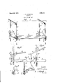
Figure 1 is a perspective view of the scaffold suspended and supported according to the present invention.
Figure 2 is a detail enlarged side elevation of one of the manually operable adjusting devices as applied to the scaffold and one of the supports therefor.
Figure 3 is a fragmentary detail view of thelower portion of Figure 2, showing a modified construction of adjustable support for the putlog of the scaffold.
Figure 4 is a fragmentary top plan view of the device as shown in Figure 2, and
Figure 5 is a fragmentary enlarged side elevation of an automatic locking device between the putlog and the supporting memher for automatically locking the putlog in adjusted position.
Referring to the drawing, 10 designates a platform of a scaffold which may be 0011- structed in the usual manner of a plurality of boards arranged lengthwise and in edge contact with each other across putlogs 11 arranged at the ends of the platform. The putlogs 11 may be of any desired construction and may be made of spaced beams of the conventional size which are of suflicient length to extend beyond the inner and outer edges of the platform 10, and which are adapted to receive between their opposite ends the vertical straps or other supports 12. which are suspended from Outriggers 13 or the like which project outwardly from the upper edge of a wall 14. The straps or supports 12 are four in number according to the present illustration and are provided at suitably spaced intervals with transverse apertures 15 extending therethrough'and of sufi'icient size to receive each a removable pin 16 which engages the lower edge of the putlog'll to support it from sliding downwardly upon the strap 12, and to thus support the platform 10. Each putlog 11 is provided at its outer end with a link 17 which is mounted upon a pivot 18 permanently upon the putlog, if desired, so that the links 17 will always be in position to engage a hook 19 carried upon the lower end of a link 20 which in turn is pivotally connected by a bolt or rivet 21 to the end of an operating lever 22. The operating lever 22 may be of forked construction so as to straddle or engage about the strap 12, and the intermediate portion of the lever 22 is apertured to receive a quickly detachable bolt 23 adapted to pivot the lever 22 to the support 12 at different points by engagement of the bolt 23 injthe selected open-v ings 15.
The lever 22 may have its inner or handle end socketed to detachably receive therein 9 the end of a handle 24. i The handle 24 may be of suitable length so as to be grasped by the person operating the device and so that suflicient leverage may be obtained for drawing up the link 20 and lifting the adjacent end of the putlog 11.
From Figure 3' it will be seen that instead of the pin 16 engaging through the strap 12 beneath the putlog 11, a stirrup 25 may be employed for engaging about and beneath the adjacent end of the putlog 11 and supported at its upper end by a removable bolt orpin 26 which is engaged in the selected openings 15 of the support. By this latter construction the adjustable pin ,26 is in a position of more easy access than are inclined inwardly and downwardly from the edge of the support 12. The putlog 11 carries a link or loop 28 pivoted to the putlog at 29 and urged at its outer end by a spring 30 against the edge of the support 12 so that the loop 28 swings into the notches .27 when the putlog 11 is raised sufliciently to bring the free end of the link into register with the notches. As the notches are inclined upwardly and out wardly, the act of lifting the putlog 11 first releases the loop 28 from its notch and the edge of the support 12 holds the loop 28 from interlocked position until the next higher notch 27 is reached.
I have illustrated and described a preferred and satisfactory embodiment of my invention, but it is obvious that changes may be made therein within the spirit and scope thereof as defined in the appended claim. What is claimed is In a scaffold, a platform having a putlog projectingfrom the edge thereof, a vertical 1 support having inwardly and downwardly inclined notches along one edge, a lever admoving the loop into a registering notch as the putlog is elevated by the lever.
Intestimony that I claim the foregoing as my invention, I have signed my name hereto.
FRANK B. J QHNSTO N.
Priority Applications (1)
| Application Number | Priority Date | Filing Date | Title |
|---|---|---|---|
| US170542A US1663131A (en) | 1927-02-24 | 1927-02-24 | Scaffold |
Applications Claiming Priority (1)
| Application Number | Priority Date | Filing Date | Title |
|---|---|---|---|
| US170542A US1663131A (en) | 1927-02-24 | 1927-02-24 | Scaffold |
Publications (1)
| Publication Number | Publication Date |
|---|---|
| US1663131A true US1663131A (en) | 1928-03-20 |
Family
ID=22620273
Family Applications (1)
| Application Number | Title | Priority Date | Filing Date |
|---|---|---|---|
| US170542A Expired - Lifetime US1663131A (en) | 1927-02-24 | 1927-02-24 | Scaffold |
Country Status (1)
| Country | Link |
|---|---|
| US (1) | US1663131A (en) |
Cited By (5)
| Publication number | Priority date | Publication date | Assignee | Title |
|---|---|---|---|---|
| US2924426A (en) * | 1953-09-08 | 1960-02-09 | Henry A Ellery | Mechanical jacking device |
| US3235956A (en) * | 1961-08-07 | 1966-02-22 | Union Tank Car Co | Method of constructing a tower structure |
| EP0332748A3 (en) * | 1988-03-17 | 1990-05-16 | Figgie International Inc. | Adjustable post and method of using the post to erect suspension scaffolding |
| WO2025251137A1 (en) * | 2024-06-07 | 2025-12-11 | 3L-Innogénie Inc. | Mobile work platform and associated method for providing access to an exterior of a multistory existing building |
| US12607025B2 (en) * | 2019-06-27 | 2026-04-21 | Quanyun SU | Falling prevention structure for attached lift scaffold |
-
1927
- 1927-02-24 US US170542A patent/US1663131A/en not_active Expired - Lifetime
Cited By (5)
| Publication number | Priority date | Publication date | Assignee | Title |
|---|---|---|---|---|
| US2924426A (en) * | 1953-09-08 | 1960-02-09 | Henry A Ellery | Mechanical jacking device |
| US3235956A (en) * | 1961-08-07 | 1966-02-22 | Union Tank Car Co | Method of constructing a tower structure |
| EP0332748A3 (en) * | 1988-03-17 | 1990-05-16 | Figgie International Inc. | Adjustable post and method of using the post to erect suspension scaffolding |
| US12607025B2 (en) * | 2019-06-27 | 2026-04-21 | Quanyun SU | Falling prevention structure for attached lift scaffold |
| WO2025251137A1 (en) * | 2024-06-07 | 2025-12-11 | 3L-Innogénie Inc. | Mobile work platform and associated method for providing access to an exterior of a multistory existing building |
Similar Documents
| Publication | Publication Date | Title |
|---|---|---|
| US1663131A (en) | Scaffold | |
| US2259789A (en) | Hook for bumper jacks or the like | |
| US1886726A (en) | Sleeve lock sling hook | |
| US2292353A (en) | Jack frame | |
| US3065987A (en) | Pallet lifting attachment | |
| US2210803A (en) | Extension ladder | |
| US1725609A (en) | Hoisting hook | |
| US2896830A (en) | Combined step and stairway and extension ladder | |
| US2310441A (en) | Extensible ladder rig | |
| US3348872A (en) | Automatic tongs | |
| US2936989A (en) | Ladder jack | |
| US2360366A (en) | Steel plate lifting tongs | |
| US2570741A (en) | Barrel lift | |
| USRE24282E (en) | R bair | |
| US4757975A (en) | Long travel beam jack | |
| US1904656A (en) | Mining drill post | |
| US2245223A (en) | Portable scaffold | |
| US1333424A (en) | Meat-hook | |
| US1577617A (en) | Scaffold hoist | |
| US2240682A (en) | Scaffold bracket | |
| US1511802A (en) | Jack | |
| US1458530A (en) | Lifting jack | |
| US2348661A (en) | Window jack | |
| US1501719A (en) | Emergency jack | |
| US965717A (en) | Portable scaffold. |