US1663118A - Baker's oven and means for controlling the heating thereof - Google Patents
Baker's oven and means for controlling the heating thereof Download PDFInfo
- Publication number
- US1663118A US1663118A US193538A US19353827A US1663118A US 1663118 A US1663118 A US 1663118A US 193538 A US193538 A US 193538A US 19353827 A US19353827 A US 19353827A US 1663118 A US1663118 A US 1663118A
- Authority
- US
- United States
- Prior art keywords
- oven
- burners
- sections
- gas
- valve
- Prior art date
- Legal status (The legal status is an assumption and is not a legal conclusion. Google has not performed a legal analysis and makes no representation as to the accuracy of the status listed.)
- Expired - Lifetime
Links
- 238000010438 heat treatment Methods 0.000 title description 11
- 239000002184 metal Substances 0.000 description 17
- 230000001276 controlling effect Effects 0.000 description 10
- 230000033001 locomotion Effects 0.000 description 7
- 230000001105 regulatory effect Effects 0.000 description 7
- 230000008933 bodily movement Effects 0.000 description 2
- 229920000136 polysorbate Polymers 0.000 description 2
- 239000002699 waste material Substances 0.000 description 2
- 102000007469 Actins Human genes 0.000 description 1
- 108010085238 Actins Proteins 0.000 description 1
- 102000015933 Rim-like Human genes 0.000 description 1
- 108050004199 Rim-like Proteins 0.000 description 1
- 238000002485 combustion reaction Methods 0.000 description 1
- 238000010276 construction Methods 0.000 description 1
- 230000003292 diminished effect Effects 0.000 description 1
- 238000009413 insulation Methods 0.000 description 1
- 239000012774 insulation material Substances 0.000 description 1
- 230000002452 interceptive effect Effects 0.000 description 1
- 238000011068 loading method Methods 0.000 description 1
Images
Classifications
-
- A—HUMAN NECESSITIES
- A21—BAKING; EDIBLE DOUGHS
- A21B—BAKERS' OVENS; MACHINES OR EQUIPMENT FOR BAKING
- A21B1/00—Bakers' ovens
- A21B1/40—Bakers' ovens characterised by the means for regulating the temperature
Definitions
- the present invehtion relates to improvements in bakers ovens particularly of that type which comprises a horizontally elongated bakingchamber having metal walls,
- the principal object of the invention is to provide an oven of the character referred to in which provision is made for compen- 1n sating for the difference in expansion of the inner and outer walls when the ovenis m use.
- Another object of the invention is to provide such an oven, the length of which-may l5 bereadily increased as desired:
- Another object of the invention is to provide means for accurately regulating or controlling the heating of the baking chamber whereby the flow of gas to the burners is 2 controlled by the temperature of the particular section of the chamber in which the burners are located, and by which the amount of gas supplied to the burners will be accurately regulated so that there will be 2 no loss or waste.
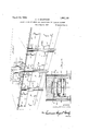
- Figure 1 1s a perspective view, of a portion of a bakers oven embodying the present improvements.
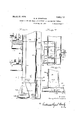
- Figure 2 is a transverse vertical, section- I throughthe oven.
- Figure 3 is a vertical sectional view of an enlarged scale through one of the side walls.
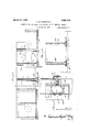
- Figure 4 is a horizontal section substantially on the line 44 of Figure 3.
- I Figure 5 is a detail elevation. partly in section on the line 55 of Figure 3.
- Figure 6 is an elevation of one side of between the inner and outer side 1927. Serial No. 193,538.
- each ovenfsection com prise suitable metal columns or uprights 3, preferably of channel. form in cross section, and inner and outer side walls 4 and 5, preferably formedby metal plates connected to the' columns or uprights as hereinafter more particularly described.
- each of the oven sections is' about five eet in length, and each of such sections includes at least one of the columns 3 at each side thereof.
- an oven of any, desired length may be initially constructed and, if desired, t eflength can be'increased or diminished'by adding or removing sections.
- the delivery end section of the oven i immovably secured in position on a suitable supporting base or floor, whereas theother sections are so supplortedthat they are permitted to move in t s5 c direction of the length I of the oven as thewalls thereof become;
- the base plate 12 can be secured to the foot of each column 3 by any suitable means, such as the angle brackets 17, 18.
- the inner side walls 4 are. formed by metal plates secured directly, to the inner facesof the columns 3 and the outer sidewalls 5 consist of plates which are supported from the channels 3 by means per mitting relative movement between said channels and plates so that the .inner walls and supporting columns, which will- ⁇ necessarily become more highly heated than the outer walls may move relative to said outer walls without distorting or otherwise aflecting the latter.
- a plurality of arms 22 are secured by rivets or similar fastening means 23 to one of the. side flanges of each channeled column 3 and extend outward from said columns.
- the outer ends of the arms 22 are bent to' lie close a ainst the inner faces of the plates forming t e outer oven wall 5, and bolts24 extend through said arms and slots 25 formed in the outer wall plates
- each arm 40 is provided atits outer endwith an abutment which contacts with the inner face of the outer oven wall and means are provided whereby said wall is clamped against said abutments.
- the abutment 41 includes member which is rigidly secured-to thearm for a clamping 40 and provides a bearing bolt 42, that extends outward between the edges of adjacent plates of theouter oven .wall 5.
- the outer terminal portion of the bolt 42 is exteriorly threaded and a nut 43 a secured thereon holds a closure member 44 in clamping relation to the oven wall.
- the pressure of the closure members 44 maintain the outer oven plates in the desired close relation tothe abutments 41,but these parts are not so rigidly connected that there cannot be a limited amount ofrelative movement between said parts to accommodate different degrees of expansion of the, inner and outer oven walls.
- the plates forming the top and bottom of the baking chamber are suitably, connected with the inner side walls 4 and the outer top is connected to the walls 5.
- the present embodiment of the invention contemplates the use of gas for this purpose, and among the objects of the invention are to control, or regulate the burners so'that the desired temperature may be maintained and waste of gas avoided when the oven is not operating.
- the upper burners are preferably separated 'from'the body of the baking chamber by the metal top or baflie 52, said burners being arranged in compartments ,whlch can be readily ventilatedyand by which the products of combustion from such burners are prevented from entering directly into the baking chamber.
- Each set of burners is divided into. a plurality of groups, each including one or more burners vand means are provided for effectively controlling the supply of gas to each of these ups. 1 1
- 60 designates a main gas supply pipe which extends substantially throughout the length of the oven.
- Each of the burners ofone of the groups of the upper'set 50 is connected to a header 61, which is connected to the "main 60 by a pipe 62.
- all of the burners of each group of the lower set 51 are connected to a header 65 through a branch pipe 66.
- each burner 1s as usual, provided with a manually operative valve or cut off 6?, and there is preferably associated with each of the upper series of burners a pilot light 70, which has a direct connection 71 with the main supply pipe 60.
- a manually operative valve 72 is provided for controlling ,the supply of gas to each pilot light.
- thermostatically controlled valve In the connection between the main supply pipe and each header 61, 65, there is arranged a thermostatically controlled valve by means of which the flow of gas 'to that header will be automatically varied in accordance with variations in the temperature in the section of the baking chamber within which the burners supplied by said header are located.
- the mechanism of such thermostatically controlled valve is illustrated merely diagrammatically in the accompanying drawing, in which 80 represents a solenoid that is connected tosaid valve controlling the upper header 61 of each group of burners and 80 the solenoid of the corresponding valve of the header 65 of the corresponding lower groupof burners, and 81 designates a portion of the circuits connecting the solenoids with suitable thermostats within the oven.
- This means includes a by-pass 90 which connects portions of the supply pipe (66 for example) at the opposite sides of the thermostatically controlled valve and an automatically acting valve in such by-pass;
- this automatic mechanism includes a diaphragm'actuated valve located in a casing 100 mounted on the by-pass 90 and the upper portion of which casing is connectedby a pipe 101 with the header supply pipe 66 beyond the valve controlled by the solenoid 80*. 1
- valve actuatin di'a hragm in the casing 100 will be expose to t e same pressure as that in the main 60, and header 65 so that said valve will be closed and the gas will flow to the header 65 and burners connected therewith through the conduit 66. If in the operation of the oven, the heat in the section thereof within which the burners connected to the header 65 are located exceeds a predetermined degree the solenoid 80 will be energized and the valve controlled thereby actuated to cut ofl the flow of gas from the main to the header 65.
- valve controlled by the diaphragm in the casing 100 will be actuated by a suitable spring to admit gas to the header through t e by-pass 90.
- the valve controlling means in the easing 100 can be such'that a uniform pressure less than that in the main 60 can be constantly maintained in the burners when the tween the burner header and main regardless of the number of burners which are in use.
- the mechanism in the casing the oven is more or less independent of the others and the temperature of every section can be readily varied as desired.
- the number of groups or zones of heating in an oven will depend upon the length thereof but the extent of each zone or group is not necessarily the same "as the length of the oven sections before referred to.
- the automatic diaphragm controlled valve referred to can be rendered inoperative by manipulating the manually operable valves in the by-pass pipe. 7
- a bakers oven comprising a horizontally elongated baking chamber formed by. a plurality of connected sections arranged end to end. and each having sheet metal inner and outer walls, one of the sections being immovably secured to the supporting base or floor, and aseries of rolls arranged beneath and supporting the other sections of the oven, substantially as and for the purpose described.
- a bakers oven comprising a horizontally elongated baking chamber formed by a plurality of connected sections arranged end to end and each having sheet metal inner and outer walls and columns or uprights between said walls, one of the sections being immovably secured to the supporting base or floor; and a series of rolls "each arranged beneath and supporting one of the columns or uprights of the other sections, whereby the last said sections may move bodily in the direction of the length of the oven relative to said immovable section.
- a bakers oven comprising a horizontally elongated baking chamber formed by a plurality of connected sections arranged end to end, and having sheet metal inner and outer walls, one of thesections being immovably secured to the supporting base or fioor,1neans supporting the other sections and permitting bodily -movement thereof relative to said immovable section in the direction of the length of the oven, and means connecting the inner and outer walls of the movable sections to permit relative longitudinal movement between said walls.
- a bakers oven comprising a horizontally elongated baking-chamber formed by a plurality of connected sections arranged end to end and each having sheet metal inner and outer walls and columns or uprights between said walls, one of the sections being immovably secured to the supporting base or floor, the columns intermediate the side walls of the other sections each having an enlarged base or foot, floor plates beneath said columns, and antifrictally elongated baking chamber formed by of connected sections arranged tlon rollers interposed between the floor plates and expanded bases of said columns.
- a bakers oven comprising a horizona plurality end to end and each including sheet metal inner and outer walls and intermediate c0l umns or uprights, the sides of the inner wall of the oven being secured directly to said uprights, one of the sections being immovably secured to the supporting base or floor, arms extending laterally from the uprights and means connecting the outer wall of the oven to said arms and permitting relative movement between them in the direction of the length of the oven, for the purpose described.
- tally elongated baking chamber formed by a plurality of, connected sections arranged end to end and each including sheet metal inner and outer walls and intermediate columns or uprights, the sides of the inner Wall tween the arms and outer oven wall for the purpose described.
- a bakers oven comprising a horizontally elongated baking chamber formed by a plurality of connected sections arranged end to end and each including sheet metal inner and outer walls and intermediate columns or uprights of channel form in cross section, the sides of the'inner wall being se cured directly to the uprights, arms secured to said; uprights and extending outward therefrom, and means connecting the outer wall of the oven to said arms and permitting relative movement between them for the purpjose described.
- a akers oven comprising a horizontally elongated baking chamber formed by a plurality of connected sections arranged end to end and each including sheet metal inner and outer walls and intermediate c011 umns or uprights, the sides of the inner wall of the oven being secured directly to said uprights, and one of the sections being immovably secured to the supporting base or floor, arms secured to the uprights and extending outward therefrom, abutments on said arms bearing against the inner face of the outer oven wall, and means for clamping the outer oven wall against said abutments.
- a bakers oven comprising a horizontally elongated baking chamber formed by a plurality of connected sections arranged end to end and each includin sheet metal inner llfIn a bakers oven, the combination with a baking chamber, of means for heat-ml ing the chambercomprising a plurality of burners, a gas supply pipe connected with all of the burners, a thermostaticall controlled valve in said supply pipe, wiiereby the flow of gas to the burners will be varied in accordance with varlatlons 1n the tem- 7.
- a bakers oven the combination with a baking chamber, of means for heating the chamber comprising a plurality of burners, a gas supply pipe connected with all of the burners, a thermostatically controlled valve in said supply pipe, whereby the flow of gas to the burners will be varied in accordance with variations in the temperature in the baking chamber, a by-pass connecting portions of the supply pipe at oppo site sides of the thermostatically controlled valve, an automatically acting valve for regulating flow through said by-pass when the thermostatically controlled valve is closed to maintain a uniform pressure of gas in all of the burners, and a manually operable valve in said by-pass between the supply pipe and said automatically actingvalve.
- a bakers oven the combination with .a baking chamber, of means for heating the chamber comprising a plurality of burners, a gas supply pipe connected with all of the burners, a thermostatically controlled valve in said supply pipe, whereby the flow of gas to the burners Wlll be varied in accordance with variations in the temperature in the baking chamber, a bypass connecting portions of the supply pipe at opposite sides of the thermostatically con-' trolled valve, an automatically acting valve for regulating flow through said by-pass when the thermostatically controlled valve is closed to maintain -a uniform pressure of gas in all of the burners, and a pilot light adjacent each burner and'independently connected to the supply pipe.
- a bakers oven the combination with a bakin chamber, of means for heating the cham er comprising a plurality of burners, a gas supply pipe connected with all of the burners, a thermostatically controlled valve in said supply pipe, whereby the flow of gas to the burners will be varied in accordance with variations in the temperature in the baking chamber, a by-pass connecting portions of the supply pipe at opposite sides of the thermostatically controlled valve, an automatically actin valve for regulating 'flow through said lay-pass when the thermostatically controlled valve is group, a gas.
Landscapes
- Life Sciences & Earth Sciences (AREA)
- Engineering & Computer Science (AREA)
- Food Science & Technology (AREA)
- Baking, Grill, Roasting (AREA)
Description
March 20,1928.
C. B. COMSTOCK BAKERS OVEN AND MEANS FOR CONTROLLING THE HEATING THEREOF Filed May 23. 1927 3 Sheets-Sheet!- C. B. COMSTOCK BAKERS OVEN AND MEANS FOR CONTROLLING THE HEATING THEREOF Filed y 25. 1927 3 Sheets-Sheet 2 arch 20, 1928.
COM STOCK BAKERS OVEN AND MEANS FOR CONTROLLING THE HEATING THEREOF Fil M y 23. 1927 5 Sheets-Sheet 3 Patented Mar. 20, 1928.
UNITED STATES PATENT OFFICE, j
COREY B. COMSTOCK, OF NEW YORK, N. Y., ASSIGNOR T COMSTOGK OVEN COMPANY,
INC., OF NEW YORK, N. Y., A CORPORATION OF NEW YOR K.
BAKERS OVEN AND MEANS FOR CONTROLLING 'JIHIil HEATING Application filed May 23,
The present invehtion relates to improvements in bakers ovens particularly of that type which comprises a horizontally elongated bakingchamber having metal walls,
and through which the articles to be baked are transported by an endless conveyor.
The principal object of the invention is to provide an oven of the character referred to in which provision is made for compen- 1n sating for the difference in expansion of the inner and outer walls when the ovenis m use.
Another object of the invention is to provide such an oven, the length of which-may l5 bereadily increased as desired:
Another object of the invention is to provide means for accurately regulating or controlling the heating of the baking chamber whereby the flow of gas to the burners is 2 controlled by the temperature of the particular section of the chamber in which the burners are located, and by which the amount of gas supplied to the burners will be accurately regulated so that there will be 2 no loss or waste.
' tion and arrangement of With the foregoing. and other objects in view, the invention consists in the construe arts that will be hereinafter more particu arly pointed out 0 and described, reference being had to the accompanying drawings in which:
Figure 1 1s a perspective view, of a portion of a bakers oven embodying the present improvements.
Figure 2 is a transverse vertical, section- I throughthe oven.
Figure 3 is a vertical sectional view of an enlarged scale through one of the side walls.-
of the oven. 1 I
Figure 4 is a horizontal section substantially on the line 44 of Figure 3. I Figure 5 is a detail elevation. partly in section on the line 55 of Figure 3.
. Figure 6 is an elevation of one side of between the inner and outer side 1927. Serial No. 193,538.
sections arranged endto end, each including double walls of sheet metal surrounding an elongated baking chamber 1, the space between said metal'wallsbeing filled with a suitable heat insulation 2. I I
The side walls of each ovenfsection com prise suitable metal columns or uprights 3, preferably of channel. form in cross section, and inner and outer side walls 4 and 5, preferably formedby metal plates connected to the' columns or uprights as hereinafter more particularly described.
Within the baking chamber 1,- is mounted I a suitable endless conveyor 6, sn ported to travel on tracks 7, 8 to convey .t 'e articles being baked longitudinally through the chamber. I v
Preferabl each of the oven sections is' about five eet in length, and each of such sections includes at least one of the columns 3 at each side thereof.
By this arrangement, an oven of any, desired length ma be initially constructed and, if desired, t eflength can be'increased or diminished'by adding or removing sections. The delivery end section of the oven i immovably secured in position on a suitable supporting base or floor, whereas theother sections are so supplortedthat they are permitted to move in t s5 c direction of the length I of the oven as thewalls thereof become;
heated.
To permit this relativemovement'between the immovabledelivery end section the other sections, in the embodiment of themventioii illustrated, each of the columns}; i
of the movable'sections is provided 'with an expanded base including a bottom plate'12 and between such baseplates and suitable rollers 14. These rollersl i support the 7 weight of the oven and permit the sections .95 floor-"plates 13, are arranged anti-friction As shown, the base plates 12 are surrounded by rim-like walls 12",.which rest on orare" flf secured to and rise from the floor, plates 13:} This .wall 12" provides a the rolls 14 may I I I and prevents the insulation material 2 from interfering with the movement ofthe oven"v sections hereinafter referredlto.
[If preferred, of
ace within whichf have a 'ted movement I similar to the walls 12 before referred to.
The base plate 12 can be secured to the foot of each column 3 by any suitable means, such as the angle brackets 17, 18.
The inner side walls 4 are. formed by metal plates secured directly, to the inner facesof the columns 3 and the outer sidewalls 5 consist of plates which are supported from the channels 3 by means per mitting relative movement between said channels and plates so that the .inner walls and supporting columns, which will-{necessarily become more highly heated than the outer walls may move relative to said outer walls without distorting or otherwise aflecting the latter. v
As shown, a plurality of arms 22 are secured by rivets or similar fastening means 23 to one of the. side flanges of each channeled column 3 and extend outward from said columns.
The outer ends of the arms 22 are bent to' lie close a ainst the inner faces of the plates forming t e outer oven wall 5, and bolts24 extend through said arms and slots 25 formed in the outer wall plates By this arrangement, while the plates of the outer wall 5 are held at fixed distances from the inner wall plates 4, the arms 22 and connecting bolts 24 may move in the slots 25 to accommodate the inner oven walls.
- In the embodiment of the invention illustrated in Figure 4,-angle plates 30, 31 are secured to the outer faces of adjacent plates of the wall 5, said angle plates abutting and mg connected by bolts or rivets 32. Suitable slots are formed in the members of the angle plates 31 which contact with the wall in alignment with the slots 25 and the securing bolts 24 extend therethrough- By this means while the plates of the outer oven wall are connected throughout the length of the oven so that all of the sections, except the immovable delivery endsection, may move together relative to said immovable section, it is ossible for the inner wall and uprights to have a limited movementrelatlve to the outer wall.
In Figures 7 and 8, there is illustrated a slightly modified construction or form of connection between the columns 3 and plates 75 of the outer side wall of the oven.
In this form, each arm 40 is provided atits outer endwith an abutment which contacts with the inner face of the outer oven wall and means are provided whereby said wall is clamped against said abutments. v
as by rivets 21,
greater expansion of the As shown, the abutment 41 includes member which is rigidly secured-to thearm for a clamping 40 and provides a bearing bolt 42, that extends outward between the edges of adjacent plates of theouter oven .wall 5. The outer terminal portion of the bolt 42 is exteriorly threaded and a nut 43 a secured thereon holds a closure member 44 in clamping relation to the oven wall. The pressure of the closure members 44 maintain the outer oven plates in the desired close relation tothe abutments 41,but these parts are not so rigidly connected that there cannot be a limited amount ofrelative movement between said parts to accommodate different degrees of expansion of the, inner and outer oven walls.
The plates forming the top and bottom of the baking chamber are suitably, connected with the inner side walls 4 and the outer top is connected to the walls 5.
While various means may be provided for heating an oven constructed as hereinbefore described, the present embodiment of the invention contemplates the use of gas for this purpose, and among the objects of the invention are to control, or regulate the burners so'that the desired temperature may be maintained and waste of gas avoided when the oven is not operating.
In the drawings, there are illustrated two sets of burners .50, 51, located respectively, above and below the upper, operative, run of the endless conveyor 6.
The upper burners are preferably separated 'from'the body of the baking chamber by the metal top or baflie 52, said burners being arranged in compartments ,whlch can be readily ventilatedyand by which the products of combustion from such burners are prevented from entering directly into the baking chamber.
Each set of burners is divided into. a plurality of groups, each including one or more burners vand means are provided for effectively controlling the supply of gas to each of these ups. 1 1
Referring particularly to Figure 1, 60 designates a main gas supply pipe which extends substantially throughout the length of the oven. Each of the burners ofone of the groups of the upper'set 50 is connected to a header 61, which is connected to the "main 60 by a pipe 62. Similarly, all of the burners of each group of the lower set 51 are connected to a header 65 through a branch pipe 66. As shown, each burner 1s, as usual, provided with a manually operative valve or cut off 6?, and there is preferably associated with each of the upper series of burners a pilot light 70, which has a direct connection 71 with the main supply pipe 60. A manually operative valve 72 is provided for controlling ,the supply of gas to each pilot light. f
P diagrammatically illustrated in Figure. 1,.
In the connection between the main supply pipe and each header 61, 65, there is arranged a thermostatically controlled valve by means of which the flow of gas 'to that header will be automatically varied in accordance with variations in the temperature in the section of the baking chamber within which the burners supplied by said header are located. The mechanism of such thermostatically controlled valve is illustrated merely diagrammatically in the accompanying drawing, in which 80 represents a solenoid that is connected tosaid valve controlling the upper header 61 of each group of burners and 80 the solenoid of the corresponding valve of the header 65 of the corresponding lower groupof burners, and 81 designates a portion of the circuits connecting the solenoids with suitable thermostats within the oven.
Means are also provided whereby when either of the thermostatically controlled valves has been actuated to cut off the supply gas to the header connected with its supply pipe, 66 for example, a uniform pressure will be maintained on all the burners of the group supplied by said header. This means includes a by-pass 90 which connects portions of the supply pipe (66 for example) at the opposite sides of the thermostatically controlled valve and an automatically acting valve in such by-pass; As
this automatic mechanism includes a diaphragm'actuated valve located in a casing 100 mounted on the by-pass 90 and the upper portion of which casing is connectedby a pipe 101 with the header supply pipe 66 beyond the valve controlled by the solenoid 80*. 1
Normally, the valve actuatin di'a hragm in the casing 100 will be expose to t e same pressure as that in the main 60, and header 65 so that said valve will be closed and the gas will flow to the header 65 and burners connected therewith through the conduit 66. If in the operation of the oven, the heat in the section thereof within which the burners connected to the header 65 are located exceeds a predetermined degree the solenoid 80 will be energized and the valve controlled thereby actuated to cut ofl the flow of gas from the main to the header 65.
As the pressure in the header falls the valve controlled by the diaphragm in the casing 100 will be actuated by a suitable spring to admit gas to the header through t e by-pass 90.
The valve controlling means in the easing 100 can be such'that a uniform pressure less than that in the main 60 can be constantly maintained in the burners when the tween the burner header and main regardless of the number of burners which are in use.
Preferably the mechanism in the casing the oven is more or less independent of the others and the temperature of every section can be readily varied as desired.
By closing the manually operable valves in the by-pass the supply of gas to the burners may be actively cut off when the thermostatically controlled valves are closed. In the drawing I have only illustrated means for controlling one group of burners.
The number of groups or zones of heating in an oven will depend upon the length thereof but the extent of each zone or group is not necessarily the same "as the length of the oven sections before referred to.
In operating an oven provided with the control means herein described, where there are a number of breaks in the baking period, that is considerable intervals of time between successive loadings of the conveyor, the automatic diaphragm controlled valve referred to can be rendered inoperative by manipulating the manually operable valves in the by-pass pipe. 7
It will be understood that the drawings herein referred to are largely diagrammatic and that there can be considerable change in the details shown without departing from the invention. Except where specifically referred to inthe appended claims, the invent-ion is not to be understood as limited ,to the exact details shown by the drawings which are to be considered illustrative rather end to end and each having sheet metal in ner and outer walls, one of the sections being immovably secured to the supporting base or floor, and means supporting the other sections and permitting bodily movement thereof relative to said immovable section in the direction of the length of the oven, for the purpose described.
'2. A bakers oven comprising a horizontally elongated baking chamber formed by. a plurality of connected sections arranged end to end. and each having sheet metal inner and outer walls, one of the sections being immovably secured to the supporting base or floor, and aseries of rolls arranged beneath and supporting the other sections of the oven, substantially as and for the purpose described. 1
.3. A bakers oven comprising a horizontally elongated baking chamber formed by a plurality of connected sections arranged end to end and each having sheet metal inner and outer walls and columns or uprights between said walls, one of the sections being immovably secured to the supporting base or floor; and a series of rolls "each arranged beneath and supporting one of the columns or uprights of the other sections, whereby the last said sections may move bodily in the direction of the length of the oven relative to said immovable section.
4. A bakers oven comprising a horizontally elongated baking chamber formed by a plurality of connected sections arranged end to end, and having sheet metal inner and outer walls, one of thesections being immovably secured to the supporting base or fioor,1neans supporting the other sections and permitting bodily -movement thereof relative to said immovable section in the direction of the length of the oven, and means connecting the inner and outer walls of the movable sections to permit relative longitudinal movement between said walls.
5. A bakers oven comprising a horizontally elongated baking-chamber formed by a plurality of connected sections arranged end to end and each having sheet metal inner and outer walls and columns or uprights between said walls, one of the sections being immovably secured to the supporting base or floor, the columns intermediate the side walls of the other sections each having an enlarged base or foot, floor plates beneath said columns, and antifrictally elongated baking chamber formed by of connected sections arranged tlon rollers interposed between the floor plates and expanded bases of said columns.
6. A bakers oven comprising a horizona plurality end to end and each including sheet metal inner and outer walls and intermediate c0l umns or uprights, the sides of the inner wall of the oven being secured directly to said uprights, one of the sections being immovably secured to the supporting base or floor, arms extending laterally from the uprights and means connecting the outer wall of the oven to said arms and permitting relative movement between them in the direction of the length of the oven, for the purpose described.
tally elongated baking chamber formed by a plurality of, connected sections arranged end to end and each including sheet metal inner and outer walls and intermediate columns or uprights, the sides of the inner Wall tween the arms and outer oven wall for the purpose described.
8. A bakers oven comprising a horizontally elongated baking chamber formed by a plurality of connected sections arranged end to end and each including sheet metal inner and outer walls and intermediate columns or uprights of channel form in cross section, the sides of the'inner wall being se cured directly to the uprights, arms secured to said; uprights and extending outward therefrom, and means connecting the outer wall of the oven to said arms and permitting relative movement between them for the purpjose described.
9. A akers oven comprising a horizontally elongated baking chamber formed by a plurality of connected sections arranged end to end and each including sheet metal inner and outer walls and intermediate c011 umns or uprights, the sides of the inner wall of the oven being secured directly to said uprights, and one of the sections being immovably secured to the supporting base or floor, arms secured to the uprights and extending outward therefrom, abutments on said arms bearing against the inner face of the outer oven wall, and means for clamping the outer oven wall against said abutments.
10. A bakers oven comprising a horizontally elongated baking chamber formed by a plurality of connected sections arranged end to end and each includin sheet metal inner llfIn a bakers oven, the combination with a baking chamber, of means for heat-ml ing the chambercomprising a plurality of burners, a gas supply pipe connected with all of the burners, a thermostaticall controlled valve in said supply pipe, wiiereby the flow of gas to the burners will be varied in accordance with varlatlons 1n the tem- 7. A bakers oven comprlslng a llOIlZOIlperature in the baking chamber, a by-pass connecting portions of the supply plpe at opposite sides of the thermostatically controlled valve, and an automatically acting valve for regulating flow through said bypass when the" thermostatically controlled valve is closed to maintain a uniform pressure of gas in all of the burners. 12. In a bakers oven, the combination with a baking chamber, of means for heating the chamber comprising a plurality of burners, a gas supply pipe connected with all of the burners, a thermostatically controlled valve in said supply pipe, whereby the flow of gas to the burners will be varied in accordance with variations in the temperature in the baking chamber, a by-pass connecting portions of the supply pipe at oppo site sides of the thermostatically controlled valve, an automatically acting valve for regulating flow through said by-pass when the thermostatically controlled valve is closed to maintain a uniform pressure of gas in all of the burners, and a manually operable valve in said by-pass between the supply pipe and said automatically actingvalve. 4
13. In a bakers oven, the combination with .a baking chamber, of means for heating the chamber comprising a plurality of burners, a gas supply pipe connected with all of the burners, a thermostatically controlled valve in said supply pipe, whereby the flow of gas to the burners Wlll be varied in accordance with variations in the temperature in the baking chamber, a bypass connecting portions of the supply pipe at opposite sides of the thermostatically con-' trolled valve, an automatically acting valve for regulating flow through said by-pass when the thermostatically controlled valve is closed to maintain -a uniform pressure of gas in all of the burners, and a pilot light adjacent each burner and'independently connected to the supply pipe.
14. In a bakers oven, the combination with a bakin chamber, of means for heating the cham er comprising a plurality of burners, a gas supply pipe connected with all of the burners, a thermostatically controlled valve in said supply pipe, whereby the flow of gas to the burners will be varied in accordance with variations in the temperature in the baking chamber, a by-pass connecting portions of the supply pipe at opposite sides of the thermostatically controlled valve, an automatically actin valve for regulating 'flow through said lay-pass when the thermostatically controlled valve is group, a gas. supply pipe having an independent connection with eaclr header, a thermostatically controlled valve in each of the connections between the supply pi e and headers, whereby the flow of gas to t e burners of'each group will be varied in accordance with variations in the temperature in the section of the oven heated by that group, a b -pass connecting the supply pipe with each eader about the thermostatically controlled valve of that header, and an automatically actingvalve for regulating flow through each said by-pass when the associated thermostatically ,controlled valve is closed, for the purpose described.
In testimony whereof I have hereunto set" my hand.
. COREY B. COMSTOCK.
Priority Applications (1)
| Application Number | Priority Date | Filing Date | Title |
|---|---|---|---|
| US193538A US1663118A (en) | 1927-05-23 | 1927-05-23 | Baker's oven and means for controlling the heating thereof |
Applications Claiming Priority (1)
| Application Number | Priority Date | Filing Date | Title |
|---|---|---|---|
| US193538A US1663118A (en) | 1927-05-23 | 1927-05-23 | Baker's oven and means for controlling the heating thereof |
Publications (1)
| Publication Number | Publication Date |
|---|---|
| US1663118A true US1663118A (en) | 1928-03-20 |
Family
ID=22714031
Family Applications (1)
| Application Number | Title | Priority Date | Filing Date |
|---|---|---|---|
| US193538A Expired - Lifetime US1663118A (en) | 1927-05-23 | 1927-05-23 | Baker's oven and means for controlling the heating thereof |
Country Status (1)
| Country | Link |
|---|---|
| US (1) | US1663118A (en) |
-
1927
- 1927-05-23 US US193538A patent/US1663118A/en not_active Expired - Lifetime
Similar Documents
| Publication | Publication Date | Title |
|---|---|---|
| US1663118A (en) | Baker's oven and means for controlling the heating thereof | |
| US1894026A (en) | Heat exchange apparatus | |
| US1386020A (en) | Fractionating apparatus | |
| US3589307A (en) | Oven | |
| US2625918A (en) | Fluid heating apparatus | |
| US1964773A (en) | Feed water control system | |
| US2431207A (en) | Continuous bake oven | |
| US2376718A (en) | Regenerative coke oven | |
| US1040688A (en) | Heater. | |
| US3002505A (en) | Tube heater | |
| US2623846A (en) | Coke oven with regenerator flow control | |
| US1790876A (en) | mueller | |
| US2845385A (en) | Coke oven battery | |
| US3221711A (en) | Ridge firing arrangement for process heaters | |
| US1473731A (en) | Furnace construction | |
| US2204155A (en) | Fluid heat exchange device | |
| US1527955A (en) | Kiln | |
| US2155954A (en) | Underfired regenerative coke oven | |
| US1338694A (en) | Furnace | |
| US2886013A (en) | Vapor generating, superheating, and reheating method and apparatus therefor | |
| US517125A (en) | Bake-oven | |
| US1965444A (en) | Automatic control system for furnace combustion air | |
| US1011061A (en) | Steam-table. | |
| US1880268A (en) | Leer | |
| US2013704A (en) | Control apparatus for furnace air |