US1663113A - Electric soldering device - Google Patents
Electric soldering device Download PDFInfo
- Publication number
- US1663113A US1663113A US30944A US3094425A US1663113A US 1663113 A US1663113 A US 1663113A US 30944 A US30944 A US 30944A US 3094425 A US3094425 A US 3094425A US 1663113 A US1663113 A US 1663113A
- Authority
- US
- United States
- Prior art keywords
- circuit
- rheostat
- conductor
- plate
- coils
- Prior art date
- Legal status (The legal status is an assumption and is not a legal conclusion. Google has not performed a legal analysis and makes no representation as to the accuracy of the status listed.)
- Expired - Lifetime
Links
- 238000005476 soldering Methods 0.000 title description 7
- 239000004020 conductor Substances 0.000 description 13
- 239000012774 insulation material Substances 0.000 description 5
- 229910000679 solder Inorganic materials 0.000 description 3
- OKTJSMMVPCPJKN-UHFFFAOYSA-N Carbon Chemical compound [C] OKTJSMMVPCPJKN-UHFFFAOYSA-N 0.000 description 2
- 229910052799 carbon Inorganic materials 0.000 description 2
- 238000010276 construction Methods 0.000 description 2
- 230000007935 neutral effect Effects 0.000 description 2
- 239000012141 concentrate Substances 0.000 description 1
- 238000010891 electric arc Methods 0.000 description 1
- 238000010438 heat treatment Methods 0.000 description 1
- 238000009413 insulation Methods 0.000 description 1
- 238000004519 manufacturing process Methods 0.000 description 1
- 230000004048 modification Effects 0.000 description 1
- 238000012986 modification Methods 0.000 description 1
- 239000007787 solid Substances 0.000 description 1
Images
Classifications
-
- B—PERFORMING OPERATIONS; TRANSPORTING
- B23—MACHINE TOOLS; METAL-WORKING NOT OTHERWISE PROVIDED FOR
- B23K—SOLDERING OR UNSOLDERING; WELDING; CLADDING OR PLATING BY SOLDERING OR WELDING; CUTTING BY APPLYING HEAT LOCALLY, e.g. FLAME CUTTING; WORKING BY LASER BEAM
- B23K11/00—Resistance welding; Severing by resistance heating
- B23K11/24—Electric supply or control circuits therefor
Definitions
- My invention relates to electric soldering devices, designed especially for use by jewelers and watch makers to solder, fill and repair articles and devices used and dealt with in these occupations, and the paramount object vof my invention is to provide an improved device of ,this character which will be economical in manufacture and highly efficient in use.
- Fig. 1 represents a ,face View of my improved device, parts being shown in sect-ion and the ,electrical instruments and connections being illustrated diagrammatically;
- y FigQ2 represents an/end elevational view of my improved device, parts being shown in section;
- Figs. 3, 4 and 5 are views of types of pencils that may be used in connection with the soldering operations.
- the preferred embodiment of my invention as illustrated in the accompanying drawing comprises a suitable resistance box 6 in which is arranged in any suitable manner a rheostat 7 comprising the usual series of coils 8 of different resistances and the usual contact posts 9 for the different coils, the series of coils being arranged in any suitable manner within the resistance box 6, while the post-s 9 protrude in circular series through the face plate l() of the resistance box.
- the circuit wires 11 and 12 for the resistance coils comprising the rheostat 7 are preferably connected to an electric plug 13 adapted to be plugged into a suitable incandescentl electric light circuit or other source of alternating current.
- a two pole switch 14 Preferably inserted in the circuit wires 1 1 and 12 is a two pole switch 14 through which the circuit may be opened and closed in a manner that will be readily understood.
- the circuit wire 11 connects with the terminal post 14 at one side of the rheostat; While the other cir ⁇ cuit wire 12, in which is incorporated a primary coil 15, is connected by a flexible connection 16 with a spring conductor lever 17 pivoted to make contact with the circular' series of contact posts 9. Said spring conlll.
- ductor lever 17 is suit-ably mounted for turning ⁇ movement upon the ,outer end of a pin 18 mounted in bushings 19 and 20 suitably arranged in the fro-nt and back plates 10 and 21, respectively, of the box.
- Said conductor lever 17 is provided with a knob 22 of suitable insulation material, whereby to be actuated.
- 23 denotes a neutral contact Apost-for the conductor lever 17 toA rest on when the device' is not in use.
- a second rheostat 24 ⁇ comprising, as before, a series of coils 25 of different resistancesand a series lof contact posts 26 which protrude in circular series through the. face plate 10i.
- the circuit wires for yrheostat 24 are indicated at 27 and 28; the wire 27 leading from the terminalpost 28 and having itsv extremity soldered as at29 to a conducting plate 30 adapted toserve as a work plate whereon to place the articles 'to be soldered.
- wire 27 is a secondary coil 31 through which power is induced from the primary circuit containing the rheostat 7 to the secondary circuit containing the rheosat 24.
- the circuit wire 28 is soldered as at 32 to the conducting plate 30 and is connected through flexible connection 33 with a spring conductor lever 34 adapted to engage the circular series of contact posts 26, there being ay neutral post 35 whereon to position this conductor lever when it is not in use.
- Said conductor lever 34 is rotatably mounted on the pin 18 and is actuated by means of a finger piece 36 of insulation material.
- Conducting levers 17 and 34 are. insulated from each other by insulation material 37 as well as from the pin 18 by insulation material 38.
- the current thus transferred from the primary circuit where the amount thereof is controlled by the rheostat 7, to the secondary circuit where the amount thereof is controlled by the rheostat 24 is thus passed through the conducting plate 30 which, as clearly shown in the drawing, is mounted in a work table or plate 39 of insulation material, the resistance box 6 being also suitably mounted upon this insulation plate 39 at the rear ofthe conductor plate 30.
- the electric current fiowing through the plate 30 is employed for the purpose of heating the article to be soldered, filled or otherwise repaired. For example, let us assume that the ends 40 of a ring element 41 are to be soldered together.
- the ring is placed upon the conductor plate 3() to receive current therefrom and to be heatedy thereby, and a little solder is dropped or placed upon the edges or points of the ring, Whichv edges or points are then engaged by the pointed end 43 ot a carbon pencil 42 to intensify or concentrate the heat at the joint to be soldered, the conductor levers 17 and 34 being manipulated so as to obtain the amount ot current necessary to bring the points-40 and solder to the necessary soldering temperature.
- the current in passing through the solid plate from terminalto terminal, also passes through the ring and to or through the edges or points 40 thereof, so that upon application of the carbon pencil an electric arc is set up Which is slowly drawn across the edges or points 40 thereby soldering them together.
- Vcarbon pencils to be employed 'for this purpose may have different types or" points; thus, tor instance the pencil 42 is shown provided With a round point 43 While the pencil 44 has a Wedge-shaped point 45, and the pencil 46 is furnished with a diamondshaped point 47.
- An electric soldering device having, in combination, a primary circuit; a rheostat incorporated therein; a secondary circuit; a rheostat incorporated in the secondary circuit; and a work plate comprising an electrical conductor 'for holding Work thereon and imparting its current thereto inserted in the secondary circuit, substantially Vas described.
- An electric solderingl device comprising an open primary circuit including rheostat coils and contacts; a conductor lever movable to engage the contacts and short circuit the coils; an open secondary circuit including rheostat coils and contactsg. a conductor lever movable to engage the contacts and short circuit the coils oi the secondary circuit; and a Work plate comprising ⁇ an electrical conductor for holding Work thereon and imparting its current thereto inserted in the secondary circuit, as and for the purpose described.
Landscapes
- Engineering & Computer Science (AREA)
- Mechanical Engineering (AREA)
- Electric Connection Of Electric Components To Printed Circuits (AREA)
Description
Patented Mar. 20, 1928.
UNI-TED" STATES SIDNEY CLAYTON, OF CHICAGO, ILLINOIS.
ELECTRlC SOLDERING DEVICE.
Application nled Hay 18, 1925. Serial No. `30,944.
My invention relates to electric soldering devices, designed especially for use by jewelers and watch makers to solder, fill and repair articles and devices used and dealt with in these occupations, and the paramount object vof my invention is to provide an improved device of ,this character which will be economical in manufacture and highly efficient in use.
Other objects will appear hereinafter.
The invention consists in the combinations and arrangements of parts hereinafter describedand claimed.
The invention will be best understood by l5 reference to the accompanying drawings,
forming a part of'this specification, yand in which,
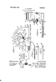
Fig. 1 represents a ,face View of my improved device, parts being shown in sect-ion and the ,electrical instruments and connections being illustrated diagrammatically;
y FigQ2 represents an/end elevational view of my improved device, parts being shown in section; and
Figs. 3, 4 and 5 are views of types of pencils that may be used in connection with the soldering operations.
The preferred embodiment of my invention as illustrated in the accompanying drawing, comprises a suitable resistance box 6 in which is arranged in any suitable manner a rheostat 7 comprising the usual series of coils 8 of different resistances and the usual contact posts 9 for the different coils, the series of coils being arranged in any suitable manner within the resistance box 6, while the post-s 9 protrude in circular series through the face plate l() of the resistance box.
The circuit wires 11 and 12 for the resistance coils comprising the rheostat 7 are preferably connected to an electric plug 13 adapted to be plugged into a suitable incandescentl electric light circuit or other source of alternating current. Preferably inserted in the circuit wires 1 1 and 12 is a two pole switch 14 through which the circuit may be opened and closed in a manner that will be readily understood. The circuit wire 11 connects with the terminal post 14 at one side of the rheostat; While the other cir` cuit wire 12, in which is incorporated a primary coil 15, is connected by a flexible connection 16 with a spring conductor lever 17 pivoted to make contact with the circular' series of contact posts 9. Said spring conlll.
Also arranged in the resistance box is a second rheostat 24` comprising, as before, a series of coils 25 of different resistancesand a series lof contact posts 26 which protrude in circular series through the. face plate 10i. The circuit wires for yrheostat 24 are indicated at 27 and 28; the wire 27 leading from the terminalpost 28 and having itsv extremity soldered as at29 to a conducting plate 30 adapted toserve as a work plate whereon to place the articles 'to be soldered. lIncorporated in the circuit. wire 27 is a secondary coil 31 through which power is induced from the primary circuit containing the rheostat 7 to the secondary circuit containing the rheosat 24. The circuit wire 28 is soldered as at 32 to the conducting plate 30 and is connected through flexible connection 33 with a spring conductor lever 34 adapted to engage the circular series of contact posts 26, there being ay neutral post 35 whereon to position this conductor lever when it is not in use. Said conductor lever 34 is rotatably mounted on the pin 18 and is actuated by means of a finger piece 36 of insulation material. Conducting levers 17 and 34 are. insulated from each other by insulation material 37 as well as from the pin 18 by insulation material 38.
The current thus transferred from the primary circuit where the amount thereof is controlled by the rheostat 7, to the secondary circuit where the amount thereof is controlled by the rheostat 24 is thus passed through the conducting plate 30 which, as clearly shown in the drawing, is mounted in a work table or plate 39 of insulation material, the resistance box 6 being also suitably mounted upon this insulation plate 39 at the rear ofthe conductor plate 30. The electric current fiowing through the plate 30 is employed for the purpose of heating the article to be soldered, filled or otherwise repaired. For example, let us assume that the ends 40 of a ring element 41 are to be soldered together. The ring is placed upon the conductor plate 3() to receive current therefrom and to be heatedy thereby, and a little solder is dropped or placed upon the edges or points of the ring, Whichv edges or points are then engaged by the pointed end 43 ot a carbon pencil 42 to intensify or concentrate the heat at the joint to be soldered, the conductor levers 17 and 34 being manipulated so as to obtain the amount ot current necessary to bring the points-40 and solder to the necessary soldering temperature. The current, in passing through the solid plate from terminalto terminal, also passes through the ring and to or through the edges or points 40 thereof, so that upon application of the carbon pencil an electric arc is set up Which is slowly drawn across the edges or points 40 thereby soldering them together. The Vcarbon pencils to be employed 'for this purpose may have different types or" points; thus, tor instance the pencil 42 is shown provided With a round point 43 While the pencil 44 has a Wedge-shaped point 45, and the pencil 46 is furnished with a diamondshaped point 47.
I/Vhile I have illustrated and described the preferred torni of construction for carrying my invention into etect, this is capable of variation and modii'ication Without departing trom the spirit of the invention. I, therefore, do not Wish to be limited to the precise details of construction set forth, but desire to avail myself of such variations and modifications as come Within the scope of the appended claims.
Having described my invention, what I claim as new and desire to secure b y Letters Patent is:
l. An electric soldering device having, in combination, a primary circuit; a rheostat incorporated therein; a secondary circuit; a rheostat incorporated in the secondary circuit; and a work plate comprising an electrical conductor 'for holding Work thereon and imparting its current thereto inserted in the secondary circuit, substantially Vas described.
2. An electric solderingl device comprising an open primary circuit including rheostat coils and contacts; a conductor lever movable to engage the contacts and short circuit the coils; an open secondary circuit including rheostat coils and contactsg. a conductor lever movable to engage the contacts and short circuit the coils oi the secondary circuit; and a Work plate comprising` an electrical conductor for holding Work thereon and imparting its current thereto inserted in the secondary circuit, as and for the purpose described. Y
In testimony whereof I have signed my name to this specification.
SIDNEY CLAYTON.
Priority Applications (1)
| Application Number | Priority Date | Filing Date | Title |
|---|---|---|---|
| US30944A US1663113A (en) | 1925-05-18 | 1925-05-18 | Electric soldering device |
Applications Claiming Priority (1)
| Application Number | Priority Date | Filing Date | Title |
|---|---|---|---|
| US30944A US1663113A (en) | 1925-05-18 | 1925-05-18 | Electric soldering device |
Publications (1)
| Publication Number | Publication Date |
|---|---|
| US1663113A true US1663113A (en) | 1928-03-20 |
Family
ID=21856819
Family Applications (1)
| Application Number | Title | Priority Date | Filing Date |
|---|---|---|---|
| US30944A Expired - Lifetime US1663113A (en) | 1925-05-18 | 1925-05-18 | Electric soldering device |
Country Status (1)
| Country | Link |
|---|---|
| US (1) | US1663113A (en) |
-
1925
- 1925-05-18 US US30944A patent/US1663113A/en not_active Expired - Lifetime
Similar Documents
| Publication | Publication Date | Title |
|---|---|---|
| US1807004A (en) | Flxebs | |
| US1663113A (en) | Electric soldering device | |
| US2680834A (en) | Testing apparatus | |
| US1745455A (en) | Soldering ladle | |
| US3263164A (en) | Electrical ground and polarity tester with thermally controlled switch means | |
| US2477887A (en) | Soldering device | |
| US2143701A (en) | Heat control iron and plug | |
| US1659911A (en) | Apparatus for performing soldering operations | |
| US2569807A (en) | Electric marking machine | |
| US1568078A (en) | Glove former | |
| US2234876A (en) | Circuit maker and breaker | |
| US2072812A (en) | Electrical circuit timer | |
| US2895120A (en) | Grounding devices for electrical components | |
| US1467181A (en) | Electric iron | |
| US1284257A (en) | Electric heating apparatus. | |
| US1373208A (en) | Therapeutic electric vibrator | |
| US2097974A (en) | Soldering implement | |
| US1006756A (en) | Electric branding device. | |
| US1308655A (en) | Electrical heating device for watchmakers use | |
| US1704461A (en) | Sign-flasher switch | |
| US1346606A (en) | Electrical apparatus | |
| US1878558A (en) | Welding apparatus | |
| GB237683A (en) | Improvements in variable electrical resistance devices | |
| DE389891C (en) | Electrically heated irons and other items without power cables and without contact pins | |
| US2376827A (en) | Step-up switch for electric arc welding |