US1651663A - Crown-block bearing for oil wells - Google Patents
Crown-block bearing for oil wells Download PDFInfo
- Publication number
- US1651663A US1651663A US468715A US46871521A US1651663A US 1651663 A US1651663 A US 1651663A US 468715 A US468715 A US 468715A US 46871521 A US46871521 A US 46871521A US 1651663 A US1651663 A US 1651663A
- Authority
- US
- United States
- Prior art keywords
- bolt
- block
- crown
- bearing blocks
- primary
- Prior art date
- Legal status (The legal status is an assumption and is not a legal conclusion. Google has not performed a legal analysis and makes no representation as to the accuracy of the status listed.)
- Expired - Lifetime
Links
- 239000003129 oil well Substances 0.000 title description 2
- 238000006073 displacement reaction Methods 0.000 description 2
- 241000531891 Alburnus alburnus Species 0.000 description 1
- 238000005553 drilling Methods 0.000 description 1
- 210000003141 lower extremity Anatomy 0.000 description 1
- 230000000717 retained effect Effects 0.000 description 1
Images
Classifications
-
- B—PERFORMING OPERATIONS; TRANSPORTING
- B66—HOISTING; LIFTING; HAULING
- B66D—CAPSTANS; WINCHES; TACKLES, e.g. PULLEY BLOCKS; HOISTS
- B66D3/00—Portable or mobile lifting or hauling appliances
- B66D3/04—Pulley blocks or like devices in which force is applied to a rope, cable, or chain which passes over one or more pulleys, e.g. to obtain mechanical advantage
- B66D3/06—Pulley blocks or like devices in which force is applied to a rope, cable, or chain which passes over one or more pulleys, e.g. to obtain mechanical advantage with more than one pulley
-
- B—PERFORMING OPERATIONS; TRANSPORTING
- B66—HOISTING; LIFTING; HAULING
- B66D—CAPSTANS; WINCHES; TACKLES, e.g. PULLEY BLOCKS; HOISTS
- B66D2700/00—Capstans, winches or hoists
- B66D2700/02—Hoists or accessories for hoists
- B66D2700/026—Pulleys, sheaves, pulley blocks or their mounting
- B66D2700/028—Pulley blocks with multiple sheaves
Definitions
- My invention relates to bearing blocks such as are used at the crown block of an oil well derrick. These bearing blocks s 11p port shafts. on which sheaves are carried,
- the principal object of my invention s to provide bearing blocks in which the ordinary type of bolts are dispensed with and in which securing means are provided whlch are so constructed that they cannot become disengaged and fall through the derr ck.
- Fig. 2 is a view on an enlarged scale showing a portion of this machinery.
- Fig. 3 is a view partly 111 section on the line 3-3 of Fig. 2.
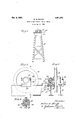
- I-beams 11 are supported on the crown block 12 of the derrick 13. Two or more I-beams 11 may be used if. desired. Supported on these I-beams are bearing blocks 14 which are channeled out and formed with longitu- .blocks through recesses 25 which. are formed in said bearing blocks. The outer walls 26 of said recesses are vertical, while the inner walls 27 are inclined inwardly from the top thereof. The lower ends 28 of the recesses 25 form channels in the upper faces of inwardly extending. walls of the groove 24. Screwed on the upper ends of the bolts 20 are nuts 21 so that these nuts bear against the upper face of the bearing blocks 14 and draw the bolts upwardly. In order that the lower ends of each bolt 20 may fit into the lower ends 28 of the recesses 25 in which the bolts 20 are discharged, the lower ends of each bolt 20 are bent from the shank thereof to form a bent ortion or head 22.
- each bolt 20 In assembling the bcfits 20 upon the bearing blocks 14, each bolt 20 has its nut 21 removed and it is inserted upwardly into its respective recess 25 so that the head 22 may be swung outwardly to a'position of rest in the lowerportion 28 of that recess 25. When each bolt 20 is in this position, its nut 21 may be screwed upon its upper end. With the bolts in this osition, the bearing blocks 14 may be slippe over a flange 23 provided on the I-beams 11 with the flange 23 extending into the groove 24.
- Cotter pins in the end of the bolts 20 and 40 prevent the nuts 21 and 41 from coming ofi even if they become loosened.
- a crown bearing block provided with a longitudinal undercut groove whereby said block may closely and slidably embrace a supporting beam and be maintained thereon against transverse displacement; a slot in said block opening into the undercut portion of the groove;
- a crown bearing block provided with a longitudinal undercut groove whereby said block may closely and slidably embrace a supporting beam and be maintained thereon against transverse displacement; a slot in said block opening into the undercut portion of said groove; and a bolt in said slot bent to engage the supporting beam for fixedly clamping said block to I the beam.
- a slot in said block opening into the undercut portion of said groove at one side thereof and positioned substantially at right angles thereto; and means in said slot to engage said beam for fixedly clamping said block to the beam.
- a crown bearing block provided with a longitudinal undercut groove whereby said bleak may closely and the undercut portion of said groove; and' a bolt in said slot bent to engage said beam for fixedly clamping said block to the beam,
- a crown hearing block provided with a longitudinal T- groove for slidably mounting said block on said beam to closely embrace said T-head; a slot opening into said T-groove at an angle thereto; and a bolt in said slot bent to enge the under side of the beam flange for nxedliy clamping said block to said beam.
- n means for securing together a primary member provided with an extending flange and a secondary member having a cavity extending therethrough, the combination of: a bolt extending through said .cavity having a head formed on the lower extremity thereof; means for pulling said head against said flange in a manner to clamp said primary and secondary members together, said bolt being formed to interlock with said secondary member for preventing the turning of said bolt in said secondar member when said head is against said ange; and means for preventing the accidental removal of said bolt from said cavity when said primary and secondary members are in contact.
- secondary member adapted to be secured to said primary member; a bolt extending through a cavity formed in said secondary member, and adapted to engage sa d prlmary member; means for causing said bolt to secure said primary and secondary members together; and means adapted to prevent a removal of said'bolt even though said means for causin said bolt to secure said primary and secondary members together is removed.
- a primary member a secondary member adapted to be secured to said primary member; a bolt extending through a cavit formed in said secondary member, and a apted to engage said primary member; means for causingi said bolt to secure said primary and secon ary mem- 10 bers together; and means adapted to prevent a removal of said bolt while said primary and secondary members are in position to be secured toget er even though said means for causing said bolt to secure said primary and secondary members together is removed.
Landscapes
- Engineering & Computer Science (AREA)
- Mechanical Engineering (AREA)
- Earth Drilling (AREA)
Description
Dec. 6, 1927; 1,651,663
- w. G. BLACK CROWN BLOCK BEARING FOR 011. WELLS Filed May 11 1921 o o e l I: i w E n gger 9', W
' Z; vgfiwvwyd 'Fi.1isaviewofthe Patented Dec. 6, 1927.
UNITED STATES PATENT OFFICE.
WALTER G. BLACK, 01' WHITTIER, CALIFORNIA, ASSIGNOR TO EMSCO DERRICK G:
EQUIPMENT COMPANY, OF LOS ANGELES, CALIFORNIA, A CORPORATION O1! CALI- roman.
Application filed Kay 11,
My invention relates to bearing blocks such as are used at the crown block of an oil well derrick. These bearing blocks s 11p port shafts. on which sheaves are carried,
5 the various cables used in the derrick passing over these sheaves. Inasmuch as these cables must pass down into the derrick, it is impracticable to close the top of the derr ck entirely. The standard forms oflbearmg blocks used in other types of machinery, if
used on a crown block, are objectionable because they have loose parts which may become detached and fall through the top of the derrick to the derrick floor below, thus injuring the operators working upon this floor. This is particularly true of the bolts used to attach the bearing blocks to the crown block structure. I
The principal object of my invention s to provide bearing blocks in which the ordinary type of bolts are dispensed with and in which securing means are provided whlch are so constructed that they cannot become disengaged and fall through the derr ck.
55 Where the ordinary bolted types 6f bearing blocks are used, it is common practice to drill the supporting structure with a plurality' of holes so that the bearing blocks may be moved on the supporting structure v to give the proper lead to the ropes and to properly align the bearing block's.
, It is a further object of my invention to provide bearing blocks which are so constructed that they can be instantly adjusted across'the derrick without the necessity of drilling any additional holes. It is a further object of my invention provide an adjustable bearing block of this pe which can be moved a very small. dis- 4 tance if desired.
Further objects and advantages will be made evident hereinafter.
' Referring to the drawings whlch are for illustrative purposes only, top of the derrick showing the crown block and its supported machinery in place thereon.
Fig. 2 is a view on an enlarged scale showing a portion of this machinery.
Fig. 3 is a view partly 111 section on the line 3-3 of Fig. 2.
4 is a similar section through an alternate form of my invention.
In the form of the invention shown, I-
CBOWN-BLOOK BEARING FOB OIL WIEIALE).
1921. Serial No. 468,715.
In assembling the bcfits 20 upon the bearing blocks 14, each bolt 20 has its nut 21 removed and it is inserted upwardly into its respective recess 25 so that the head 22 may be swung outwardly to a'position of rest in the lowerportion 28 of that recess 25. When each bolt 20 is in this position, its nut 21 may be screwed upon its upper end. With the bolts in this osition, the bearing blocks 14 may be slippe over a flange 23 provided on the I-beams 11 with the flange 23 extending into the groove 24. When the bearing blocks 14' have been properly positioned upon the I-beams 11, the nuts 21 are ti htened upon the bolts 20 so as to draw the olt heads 22 upwardly into tight clampin relation with the lower surface of the anges 23 of the I-beams 11. This rigidly "retains the bearing blocks 14 in their proper position upon the I-beams 11. Y
It is to be noted that when the bearing blocks 14 are slid upon the flanges 23 of the I-beams 11 the bolts 20 are securely retained against rotation by the engagement of the bolt heads 22 with the side walls of the lower portion 28 of the recess 25 in which that boltis disposed. Furthermore, even though the nuts 21 were removed from the bolts 20, the latter are prevented from accidental removal from the recess 25 in which they are disposed by contact of the heads 22 with the bottom of the recess portion 28. By loosening the nuts 21, the bearing blocks may be moved a short distance on the channels 11, thus allowing the shafts to be accurately lined up in any position. It is ossible by hitting the bearing blocks a llght blow of the hammer to move them a sixtyfourth of an inch and to clamp them down after they have been so moved In the alternate form of my invention shown in Fig. 4, hook bolts are used, these bolts being pulled up with nuts 41 to clamp upon the flanges 23. It will be seen that neither the bolts 40 nor the bolts 20 can come out of the bearing blocks even if the nuts 21 become greatly. loosened due to vibration.
Cotter pins in the end of the bolts 20 and 40 prevent the nuts 21 and 41 from coming ofi even if they become loosened.
I claim as my invention:
1. In a device of the character described, the combination of: a crown bearing block provided with a longitudinal undercut groove whereby said block may closely and slidably embrace a supporting beam and be maintained thereon against transverse displacement; a slot in said block opening into the undercut portion of the groove; and
means in said slot adapted to engage the llseam for fixedly clamping said block to the cam.
2. In a device of the character described, the combination of: a crown bearing block provided with a longitudinal undercut groove whereby said block may closely and slidably embrace a supporting beam and be maintained thereon against transverse displacement; a slot in said block opening into the undercut portion of said groove; and a bolt in said slot bent to engage the supporting beam for fixedly clamping said block to I the beam.
placement; a slot in said block opening into the undercut portion of said groove at one side thereof and positioned substantially at right angles thereto; and means in said slot to engage said beam for fixedly clamping said block to the beam.
4. In a device of the character described, the combination of: a crown bearing block provided with a longitudinal undercut groove whereby said bleak may closely and the undercut portion of said groove; and' a bolt in said slot bent to engage said beam for fixedly clamping said block to the beam,
said slot and said bolt so shaped and positioned asto prevent the withdrawal of said bolt from said slot when said block is mounted. 5. In combination with a supporting beam having a longitudinal T-head: a crown hearing block provided with a longitudinal T- groove for slidably mounting said block on said beam to closely embrace said T-head; a slot opening into said T-groove at an angle thereto; and a bolt in said slot bent to enge the under side of the beam flange for nxedliy clamping said block to said beam.
6. n means for securing together a primary member provided with an extending flange and a secondary member having a cavity extending therethrough, the combination of: a bolt extending through said .cavity having a head formed on the lower extremity thereof; means for pulling said head against said flange in a manner to clamp said primary and secondary members together, said bolt being formed to interlock with said secondary member for preventing the turning of said bolt in said secondar member when said head is against said ange; and means for preventing the accidental removal of said bolt from said cavity when said primary and secondary members are in contact.
7. In means for securing together a primary member provided with an extending flange, and a. secondary member having a cavity extending therethrough, said flange of Inn said primary member extending at right to clamp said primary and secondary members together, said'bolt being formed to interlock with said secondary member for preventing the turning of said bolt in said secondary member when said head is against said flange; and means for preventing the accidental removal of said bolt from said cavity when said primary and secondary members are in contact.
8. In combination: a primary member; a
secondary member adapted to be secured to said primary member; a bolt extending through a cavity formed in said secondary member, and adapted to engage sa d prlmary member; means for causing said bolt to secure said primary and secondary members together; and means adapted to prevent a removal of said'bolt even though said means for causin said bolt to secure said primary and secondary members together is removed.
9. In combination: a primary member; a secondary member adapted to be secured to said primary member; a bolt extending through a cavit formed in said secondary member, and a apted to engage said primary member; means for causingi said bolt to secure said primary and secon ary mem- 10 bers together; and means adapted to prevent a removal of said bolt while said primary and secondary members are in position to be secured toget er even though said means for causing said bolt to secure said primary and secondary members together is removed.
In testimony whereof, I have hereunto set my hand at Los Angeles, California, this 20th day of April, 1921.
lVALTER G. BLACK.
Priority Applications (1)
| Application Number | Priority Date | Filing Date | Title |
|---|---|---|---|
| US468715A US1651663A (en) | 1921-05-11 | 1921-05-11 | Crown-block bearing for oil wells |
Applications Claiming Priority (1)
| Application Number | Priority Date | Filing Date | Title |
|---|---|---|---|
| US468715A US1651663A (en) | 1921-05-11 | 1921-05-11 | Crown-block bearing for oil wells |
Publications (1)
| Publication Number | Publication Date |
|---|---|
| US1651663A true US1651663A (en) | 1927-12-06 |
Family
ID=23860943
Family Applications (1)
| Application Number | Title | Priority Date | Filing Date |
|---|---|---|---|
| US468715A Expired - Lifetime US1651663A (en) | 1921-05-11 | 1921-05-11 | Crown-block bearing for oil wells |
Country Status (1)
| Country | Link |
|---|---|
| US (1) | US1651663A (en) |
Cited By (1)
| Publication number | Priority date | Publication date | Assignee | Title |
|---|---|---|---|---|
| US9366276B1 (en) | 2013-03-29 | 2016-06-14 | G8R, Llc | Uplift and lateral restraint system to secure a drilling rig to an offshore platform |
-
1921
- 1921-05-11 US US468715A patent/US1651663A/en not_active Expired - Lifetime
Cited By (1)
| Publication number | Priority date | Publication date | Assignee | Title |
|---|---|---|---|---|
| US9366276B1 (en) | 2013-03-29 | 2016-06-14 | G8R, Llc | Uplift and lateral restraint system to secure a drilling rig to an offshore platform |
Similar Documents
| Publication | Publication Date | Title |
|---|---|---|
| US4090796A (en) | Device for fastening needle case to yoke in universal joint of trunnion type | |
| PT1588017E (en) | Attachment means for drilling equipment | |
| US3465995A (en) | I-beam clamp | |
| US2242783A (en) | Elevator link and handle | |
| US1651663A (en) | Crown-block bearing for oil wells | |
| US1612769A (en) | Expansible locking key | |
| US2303312A (en) | Well pipe jack | |
| US4625820A (en) | Crawler frame to base frame connection | |
| US2282685A (en) | Cable anchor | |
| US1883915A (en) | Dipper stick foot piece | |
| US1090955A (en) | Metallic derrick. | |
| US1578656A (en) | Crown-block bolt | |
| US3273658A (en) | Feeding slide arrangement for rock drilling | |
| US1699636A (en) | Adjustable guide shell | |
| US2810597A (en) | Fastening device | |
| US2304752A (en) | Railway tie tool | |
| US1240966A (en) | Clamp. | |
| US1346907A (en) | Bolt-lock | |
| US1942684A (en) | Earth anchor | |
| US1440576A (en) | Metal structure and method of securing parts | |
| US1436566A (en) | Take-up for skip-hoist ropes | |
| US1314996A (en) | Well-elevator | |
| US1347211A (en) | Attachment for rope-blocks | |
| US2805073A (en) | Detachable self locking driving device | |
| US933386A (en) | Oil-well derrick. |