US165144A - Iiprovement in apparatus for transmitting and regulating motion - Google Patents
Iiprovement in apparatus for transmitting and regulating motion Download PDFInfo
- Publication number
- US165144A US165144A US165144DA US165144A US 165144 A US165144 A US 165144A US 165144D A US165144D A US 165144DA US 165144 A US165144 A US 165144A
- Authority
- US
- United States
- Prior art keywords
- wheel
- cone
- transmitting
- iiprovement
- shaft
- Prior art date
- Legal status (The legal status is an assumption and is not a legal conclusion. Google has not performed a legal analysis and makes no representation as to the accuracy of the status listed.)
- Expired - Lifetime
Links
- 230000001105 regulatory effect Effects 0.000 title description 2
- 239000003818 cinder Substances 0.000 description 1
- 239000000428 dust Substances 0.000 description 1
- 210000003746 feather Anatomy 0.000 description 1
- 210000003141 lower extremity Anatomy 0.000 description 1
- 230000002459 sustained effect Effects 0.000 description 1
Images

Classifications
-
- F—MECHANICAL ENGINEERING; LIGHTING; HEATING; WEAPONS; BLASTING
- F16—ENGINEERING ELEMENTS AND UNITS; GENERAL MEASURES FOR PRODUCING AND MAINTAINING EFFECTIVE FUNCTIONING OF MACHINES OR INSTALLATIONS; THERMAL INSULATION IN GENERAL
- F16H—GEARING
- F16H61/00—Control functions within control units of change-speed- or reversing-gearings for conveying rotary motion ; Control of exclusively fluid gearing, friction gearing, gearings with endless flexible members or other particular types of gearing
- F16H61/66—Control functions within control units of change-speed- or reversing-gearings for conveying rotary motion ; Control of exclusively fluid gearing, friction gearing, gearings with endless flexible members or other particular types of gearing specially adapted for continuously variable gearings
- F16H61/664—Friction gearings
- F16H61/6645—Friction gearings controlling shifting exclusively as a function of speed and torque
-
- Y—GENERAL TAGGING OF NEW TECHNOLOGICAL DEVELOPMENTS; GENERAL TAGGING OF CROSS-SECTIONAL TECHNOLOGIES SPANNING OVER SEVERAL SECTIONS OF THE IPC; TECHNICAL SUBJECTS COVERED BY FORMER USPC CROSS-REFERENCE ART COLLECTIONS [XRACs] AND DIGESTS
- Y10—TECHNICAL SUBJECTS COVERED BY FORMER USPC
- Y10T—TECHNICAL SUBJECTS COVERED BY FORMER US CLASSIFICATION
- Y10T74/00—Machine element or mechanism
- Y10T74/18—Mechanical movements
- Y10T74/18056—Rotary to or from reciprocating or oscillating
- Y10T74/18088—Rack and pinion type
- Y10T74/18096—Shifting rack
Definitions
- J. ZENGEL. A lAppauatus for Transmitting and Fvegulatngl Mnlt'inm.. ⁇ N0. l65,l44 Y Pate'ntgdlrune29,l875
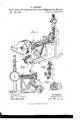
- the wheels D engage the bevelpinion E at the lower end of the shaft F, which inclines upward, as shown, having bearings in standards d e and brace h, and secured xedly at the axial center of the cone H, so that the surface of the cone that is uppermost is always parallelV to the shaft I, which works in bearings near the top of the standards d e,
- the shaft I is provided between its bearings with the groove m, to receive the feather n on the balljoint p, placed at the center of the friction- Wheel N, 'the periphery of which impin ges upon the cone H.
- the wheel can rotate lower end of the hollow vertical shaft R, which works in bearings in the plate o, secured near the top of the standard w, and is sustained by the collar x, above which is placed the governor S, formed of two spring-bars., y, provided at their centers with the weights z, and
- the shaft carrying the wheel P works in bearin gs in the standard w and arm c', and is provided between the wh eel and standard with the fixed pinion h', operating the internally toothed traveling rack T, which moves through the strapI el', which also incloses the pinion h.
- the end of the rack adjacent the wheel N is provided with a bar, l', having the loops mf, working upon the guide-rod U.
- the plate V is journaled at each end in bar Z, and provided above and below with the arms al, which extend over and upon oppositesides. of the collar q on the wheel N..
- the fork Wextends from the plate V, as shown, to prevent the wheel coming in contact with the bar l.
- the traveling rack T provided with lthe bar Z', having the arms u', in combination With the Wheel N and cone Il, substantially as specied.
Landscapes
- Engineering & Computer Science (AREA)
- General Engineering & Computer Science (AREA)
- Mechanical Engineering (AREA)
- Transmission Devices (AREA)
Description
J. ZENGEL. A lAppauatus for Transmitting and Fvegulatngl Mnlt'inm.. `N0. l65,l44 Y Pate'ntgdlrune29,l875
I f 1l' l Je Fly. 7. P u
l 1.7L a N- I uro THE GRAPHIC C0,PHOTOLITH.'!9&41 PARK PLACEJLY.
JOSEPH ZENGEL, OF QUINCY, ILLINOIS.
IMPROVEMENT IN 4APPAR/l`l`ll8 FOR TRANSll/HTTING AND REGULATINGlVlOTION.
Specification forming part of Letters Patent N0. lgll., dated June 29, i875; application filed April 6, 1875.
To all whom it may concern:
Be it known that'l, Jesi-:PH ZENGEL, of Quincy, Illinois, have invented certain new and useful Improvements in Machines for Itegnlating and Transmitting Motion, of which `the following is a spccilication, reference bela platform placed in proper relation to the car-axle B, to which are rigidly secured. the bevel-gear wheels I), provided at their center with the circular ratchet a, upon which oper- `ates the spring-pawl b. By this arrangement the device is operated when the car moves either way. The wheels D engage the bevelpinion E at the lower end of the shaft F, which inclines upward, as shown, having bearings in standards d e and brace h, and secured xedly at the axial center of the cone H, so that the surface of the cone that is uppermost is always parallelV to the shaft I, which works in bearings near the top of the standards d e,
.through both of which it projects, being at one end supplied with the grooved pulleywheel L, over which passes the belt, connecting with a wheel on the end of the shaft of the fan M, which is secured to the platform A, and provided w1th the conduit i to deliver,
and the apertures l toreceive, the air, the latter being covered with gauze or other suitable means to prevent the entrance of dust or cinders into the fan, which, being operated by the belt, supplies the car with air. The shaft I is provided between its bearings with the groove m, to receive the feather n on the balljoint p, placed at the center of the friction- Wheel N, 'the periphery of which impin ges upon the cone H. Thus the wheel can rotate lower end of the hollow vertical shaft R, which works in bearings in the plate o, secured near the top of the standard w, and is sustained by the collar x, above which is placed the governor S, formed of two spring-bars., y, provided at their centers with the weights z, and
having their lower extremities connected with the plate a', to the center of which is secured the upper end of the. rod b', which extends downward, having its lower end securedvto the strap d. Thus, as the governor is operated the strap is elevated or lowered. The shaft carrying the wheel P works in bearin gs in the standard w and arm c', and is provided between the wh eel and standard with the fixed pinion h', operating the internally toothed traveling rack T, which moves through the strapI el', which also incloses the pinion h. The end of the rack adjacent the wheel N is provided with a bar, l', having the loops mf, working upon the guide-rod U. The plate V is journaled at each end in bar Z, and provided above and below with the arms al, which extend over and upon oppositesides. of the collar q on the wheel N.. The fork Wextends from the plate V, as shown, to prevent the wheel coming in contact with the bar l.
The operation of this invention is as follows: Motion being communicated to the axle B, it is thence transmitted to the shaft F, which actuates the cone H, rotating the wheel N and shaft I, thus operating fan M 5 also, through the intermediate attachments, to the governor S. The initial position of the frictionwheel N being at the base or greatest circumference of the cone, and the upper teeth of the rack T in contact with the pinion h', as the speed of the axle B increases the rack Tis elevated, its lower teeth engaging the pinion, and is drawn forward, which causes the arms n of the plate V to deflect the wheel N toward the crown-gear P, in which position it moves t0- ward the apex of the cone until the maximum speed is reached, when the wheel stands still.
2 reame Asthe speed slaekens the governor contracts.
pinion hf, which reverses the movement of the rack and the position of the Wheel N When it rides down the cone H. V
Thus it is obvious that the movement of the shaft I must be uniform, since the proportion of the surface of the cone actuating the Wheel Nis in proportion to the movement ofthe axle B, a regularly-decreasing amount of surface being presented as the speed increases.
W hat l claim as my invention, and desire to secure by Letters Patent, is-
1. The Wheel N, provided With the ball and Socket p, in combination With the shaft I and cone H, substantially as set forth.
, .2. .The traveling rack T, provided with lthe bar Z', having the arms u', in combination With the Wheel N and cone Il, substantially as specied.
3. The combination of the cone H,Wheel N, governor S, and rack T, substantially as shown and described.
In testimony that I claim the foregoing improvements in machines for regulating and transmitting motion, as above described, I have hereunto set my hand and seal this 18th day7 of March, 1875.
` JOSEPH ZENGEL. [L. 5.]
Witnesses:
FRANZ KIEFER, WILHELMv FOLKWEID.
Publications (1)
| Publication Number | Publication Date |
|---|---|
| US165144A true US165144A (en) | 1875-06-29 |
Family
ID=2234553
Family Applications (1)
| Application Number | Title | Priority Date | Filing Date |
|---|---|---|---|
| US165144D Expired - Lifetime US165144A (en) | Iiprovement in apparatus for transmitting and regulating motion |
Country Status (1)
| Country | Link |
|---|---|
| US (1) | US165144A (en) |
-
0
- US US165144D patent/US165144A/en not_active Expired - Lifetime
Similar Documents
| Publication | Publication Date | Title |
|---|---|---|
| US1074011A (en) | Windmill. | |
| US260761A (en) | Plant-sprinkler | |
| US30362A (en) | Propelling machinery by horse-power | |
| US481718A (en) | Spraying-machine | |
| US161585A (en) | Improvement in scroll-sawing-machines | |
| US265537A (en) | Chaeles z | |
| US324434A (en) | totman | |
| US214466A (en) | Improvement in car-propellers | |
| US230456A (en) | Check-row attachment for corn-planters | |
| USRE9268E (en) | And sylvanus d | |
| US113594A (en) | Improvement in spinning-wheels | |
| US225727A (en) | John s | |
| US122987A (en) | Improvement in animal-powers | |
| US1093881A (en) | Wind-wheel. | |
| US184761A (en) | Improvement in motive-powers | |
| US173634A (en) | Improvement in millstone-dressing machines | |
| US772586A (en) | Lifting-derrick. | |
| USRE2723E (en) | Edsell totman | |
| US127800A (en) | Improvement in animal powers | |
| US210702A (en) | Improvement in harrows | |
| US1024066A (en) | Traction-vehicle. | |
| US230426A (en) | peters | |
| US482678A (en) | Coupling-pole | |
| US382525A (en) | Mechanical motor | |
| US142324A (en) | Improvement in windmills |