US1649513A - Cotter-pin tool - Google Patents
Cotter-pin tool Download PDFInfo
- Publication number
- US1649513A US1649513A US154983A US15498326A US1649513A US 1649513 A US1649513 A US 1649513A US 154983 A US154983 A US 154983A US 15498326 A US15498326 A US 15498326A US 1649513 A US1649513 A US 1649513A
- Authority
- US
- United States
- Prior art keywords
- cotter
- prongs
- cotter pin
- jaw
- pin tool
- Prior art date
- Legal status (The legal status is an assumption and is not a legal conclusion. Google has not performed a legal analysis and makes no representation as to the accuracy of the status listed.)
- Expired - Lifetime
Links
Images

Classifications
-
- B—PERFORMING OPERATIONS; TRANSPORTING
- B25—HAND TOOLS; PORTABLE POWER-DRIVEN TOOLS; MANIPULATORS
- B25B—TOOLS OR BENCH DEVICES NOT OTHERWISE PROVIDED FOR, FOR FASTENING, CONNECTING, DISENGAGING OR HOLDING
- B25B27/00—Hand tools, specially adapted for fitting together or separating parts or objects whether or not involving some deformation, not otherwise provided for
- B25B27/02—Hand tools, specially adapted for fitting together or separating parts or objects whether or not involving some deformation, not otherwise provided for for connecting objects by press fit or detaching same
- B25B27/08—Hand tools, specially adapted for fitting together or separating parts or objects whether or not involving some deformation, not otherwise provided for for connecting objects by press fit or detaching same inserting or withdrawing cotter pins
-
- Y—GENERAL TAGGING OF NEW TECHNOLOGICAL DEVELOPMENTS; GENERAL TAGGING OF CROSS-SECTIONAL TECHNOLOGIES SPANNING OVER SEVERAL SECTIONS OF THE IPC; TECHNICAL SUBJECTS COVERED BY FORMER USPC CROSS-REFERENCE ART COLLECTIONS [XRACs] AND DIGESTS
- Y10—TECHNICAL SUBJECTS COVERED BY FORMER USPC
- Y10T—TECHNICAL SUBJECTS COVERED BY FORMER US CLASSIFICATION
- Y10T29/00—Metal working
- Y10T29/53—Means to assemble or disassemble
- Y10T29/53796—Puller or pusher means, contained force multiplying operator
- Y10T29/53809—Cotter pin and cooperating member
- Y10T29/53813—Plier type means
Definitions
- This invention relates to an improved tool which is especially adapted for use in connection with cotter pins to facilitate applicatlon and removal of the same.
- the invention has reference to a structure of this kind which includes cooperating claw members of a configuration to efiectively engage either the head or the prong of the cotter pin, for withdrawing, inserting,.spreading prongs, et cetera.
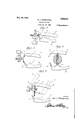
- Figure 1 is a perspective view of the complete tool constructed in accordance with the invention
- Fig. 2 is an enlarged detail persp view of certain of the details
- Fig. 3 is a. side view of'fragmentary portions of the jaw portions showing the pin engaging members together
- Fig. 4 is a View somewhat like Fig. 3 showing said members engaged with the headed end of a cotter pin for extracting the same,
- Fig. 5 is a view showing the manner in which these tools are used for bending the prongs together for subsequent removal of the pins, I
- Fig. 6 is a view showin the manner in which the prongs are spread
- Fig, 7 is a view showing the manner in which the prongs are bent for securing the same in place.
- the reference character ldesignates the handles which are disposed in crossed relation and pivotally connected together as at 2.
- the portions extending outwardly beyond the handles form what may be defined as jaw portions 3 and 4 respectively.
- the jaw portion 3 is provided adjacent its outer end with 'two or more recesses 5 forming sockets for reception of the head 6 of a cotter pin.
- Formed integral with the free end portion is an extension 7 of Ion tudinally curved configuration, the same eing bifurcated at its free end as at 8 and the furcations 9 serving as jaws to straddle the shank of the cotter pin, et cetera.
- this pin-gripping extension is ctive nut and bringing the formed with a groove 10 as shown plainly in Fig. 1.
- Formed integral with the free end portion of the jaw member 4 is an enlargement 11 having a V-shaped central portion acting as a spreader. The apex of this spreader is located opposite the aforesaid recesses 5.
- the reference character 12 designates an appropriately curved claw for cooperation with the jaws 9. The gripping fingers of the claw are shaped to overlap the jaws 9 when the members 3 and 4 are in the relationship shown in Fig. 3, for instance.
- a suitable spring 13 is employed between the handles and on the right hand side of the pivotal connection2 in Fig. 1 to hold the jaw members 3 and 4 normally spaced apart.
- Fig. 1 The normal position of the parts is represented in Fig. 1.
- Fig. '3 The extreme closed position is represented in Fig. '3.
- Fig. 4 A similar position is represented in Fig. 4 wherein it will be seen that the 'aws 9 straddle the shank of the cotter pin w ile the gripping fingers of the claw 12 also straddle the same so that by holding the handles together against the tension of the spring 13, the cotter pin may be readily extracted from the bolt in which it is mounted. Assuming that the cotter pin must be withdrawn and that the ends of the prongs have been bent apart in an obvious manner (as represented in Fig.
- levers including handle portions and jaw portions, the free end of one jaw portion being provided with a longitudinal groove and terminating in jaws at'opposite sides of said grooves, and a claw extending from the end portion of the complemental jaw and having a notched end portion arranged to overlap said gripping jaws.
Description
Nov, 15, 1927;
1,649,513 P, J. DANDENEAU COTTER PIN TOOL Filed Dec. 15. 1926 2 Sheets-Sheet l Inventor a x I 4 ,Attomy Nov. 15, 1927.
v P. J. DANDENEAU COTTER PIN TOOL 2 Sheets-sheaf 2 Filed Dec. 15., 1926 Alto r212] Patented Nov. 15,1927.
UNITED STATES PAUL J. DANDENEAU, OF LAWNDALE, CALIFORNIA.
COTTER-PIN TOOL.
Application filed. December 15, 1928. Serial No. 154,983.
This invention relates to an improved tool which is especially adapted for use in connection with cotter pins to facilitate applicatlon and removal of the same.
Briefly, the invention has reference to a structure of this kind which includes cooperating claw members of a configuration to efiectively engage either the head or the prong of the cotter pin, for withdrawing, inserting,.spreading prongs, et cetera.
Other structural details, features and advantages of the invention will become apparent from the following description and claim. 0 In the accompanying drawings forming a part of this application and in which like numerals are employed to designate like parts throughout the same:
Figure 1 is a perspective view of the complete tool constructed in accordance with the invention,
Fig. 2 is an enlarged detail persp view of certain of the details,
Fig. 3 is a. side view of'fragmentary portions of the jaw portions showing the pin engaging members together,
Fig. 4 is a View somewhat like Fig. 3 showing said members engaged with the headed end of a cotter pin for extracting the same,
Fig. 5 is a view showing the manner in which these tools are used for bending the prongs together for subsequent removal of the pins, I
Fig. 6 is a view showin the manner in which the prongs are spread,
Fig, 7 is a view showing the manner in which the prongs are bent for securing the same in place.
Referring to the drawings in detail it will be seen that the reference character ldesignates the handles which are disposed in crossed relation and pivotally connected together as at 2. The portions extending outwardly beyond the handles form what may be defined as jaw portions 3 and 4 respectively. The jaw portion 3 is provided adjacent its outer end with 'two or more recesses 5 forming sockets for reception of the head 6 of a cotter pin. Formed integral with the free end portion is an extension 7 of Ion tudinally curved configuration, the same eing bifurcated at its free end as at 8 and the furcations 9 serving as jaws to straddle the shank of the cotter pin, et cetera. The underside of this pin-gripping extension is ctive nut and bringing the formed with a groove 10 as shown plainly in Fig. 1. Formed integral with the free end portion of the jaw member 4 is an enlargement 11 having a V-shaped central portion acting as a spreader. The apex of this spreader is located opposite the aforesaid recesses 5. The reference character 12 designates an appropriately curved claw for cooperation with the jaws 9. The gripping fingers of the claw are shaped to overlap the jaws 9 when the members 3 and 4 are in the relationship shown in Fig. 3, for instance. It is yet to be pointed out that a suitable spring 13 is employed between the handles and on the right hand side of the pivotal connection2 in Fig. 1 to hold the jaw members 3 and 4 normally spaced apart.
The normal position of the parts is represented in Fig. 1. The extreme closed position is represented in Fig. '3. A similar position is represented in Fig. 4 wherein it will be seen that the 'aws 9 straddle the shank of the cotter pin w ile the gripping fingers of the claw 12 also straddle the same so that by holding the handles together against the tension of the spring 13, the cotter pin may be readily extracted from the bolt in which it is mounted. Assuming that the cotter pin must be withdrawn and that the ends of the prongs have been bent apart in an obvious manner (as represented in Fig. 5) and it is desired to move them together to facilitate extraction, this is done by engaging the member 7 with one prong andth'e claw 12 with the other prong and then moving the handles together to also move the bent prongs together. Assuming that the cotter pin has just beeninserted through a hole in the bolt and it is desired to spread the prongs, this is done by inserting the head in one of the recesses 5 and engaging the free end of the prongs with the spreader 11 as represented in Fig. 6. Obviously by movin the jaw members 3 and 4 towards each other, the spreading action will take place. Assuming that the cotter pin is to be bent somewhat as represented by dotted lines in Fig. 7, this is done by engaging the jaws 9 behind the retaining claw 12 against the free end portions of the prongs and then moving the tool from the full line position to the dotted line position represented.
Undoubtedly, by considering the details of description in connection with the drawings a clear understanding of the construction as means ed relation, said levers including handle portions and jaw portions, the free end of one jaw portion being provided with a longitudinal groove and terminating in jaws at'opposite sides of said grooves, and a claw extending from the end portion of the complemental jaw and having a notched end portion arranged to overlap said gripping jaws. I
' In testimony whereof I aflix my signature.
PAUL J. DANDENEAU-
Priority Applications (1)
| Application Number | Priority Date | Filing Date | Title |
|---|---|---|---|
| US154983A US1649513A (en) | 1926-12-15 | 1926-12-15 | Cotter-pin tool |
Applications Claiming Priority (1)
| Application Number | Priority Date | Filing Date | Title |
|---|---|---|---|
| US154983A US1649513A (en) | 1926-12-15 | 1926-12-15 | Cotter-pin tool |
Publications (1)
| Publication Number | Publication Date |
|---|---|
| US1649513A true US1649513A (en) | 1927-11-15 |
Family
ID=22553645
Family Applications (1)
| Application Number | Title | Priority Date | Filing Date |
|---|---|---|---|
| US154983A Expired - Lifetime US1649513A (en) | 1926-12-15 | 1926-12-15 | Cotter-pin tool |
Country Status (1)
| Country | Link |
|---|---|
| US (1) | US1649513A (en) |
Cited By (4)
| Publication number | Priority date | Publication date | Assignee | Title |
|---|---|---|---|---|
| US2693726A (en) * | 1951-03-14 | 1954-11-09 | Warren E Coonan | Cotter pin spreading pliers |
| US2802383A (en) * | 1953-04-06 | 1957-08-13 | George H Babyak | Cotter key spreading tool and dies |
| US4841821A (en) * | 1987-09-09 | 1989-06-27 | Cooper Kenneth L | J-nut plier |
| EP3403768A1 (en) | 2017-05-16 | 2018-11-21 | MAN Truck & Bus AG | Device for bending a splint |
-
1926
- 1926-12-15 US US154983A patent/US1649513A/en not_active Expired - Lifetime
Cited By (7)
| Publication number | Priority date | Publication date | Assignee | Title |
|---|---|---|---|---|
| US2693726A (en) * | 1951-03-14 | 1954-11-09 | Warren E Coonan | Cotter pin spreading pliers |
| US2802383A (en) * | 1953-04-06 | 1957-08-13 | George H Babyak | Cotter key spreading tool and dies |
| US4841821A (en) * | 1987-09-09 | 1989-06-27 | Cooper Kenneth L | J-nut plier |
| EP3403768A1 (en) | 2017-05-16 | 2018-11-21 | MAN Truck & Bus AG | Device for bending a splint |
| DE102017004648A1 (en) | 2017-05-16 | 2018-11-22 | Man Truck & Bus Ag | Device for bending a splint |
| US10864621B2 (en) | 2017-05-16 | 2020-12-15 | Man Truck & Bus Ag | Device for bending a split pin |
| RU2766629C2 (en) * | 2017-05-16 | 2022-03-15 | Ман Трак Энд Бас Аг | Cotter pin bending device |
Similar Documents
| Publication | Publication Date | Title |
|---|---|---|
| US1557370A (en) | Tool for applying and removing laundry markers | |
| US1661365A (en) | Pliers | |
| US2755541A (en) | Plier tool for applying and removing sheet metal fasteners | |
| US2655064A (en) | Ratcheting wrench | |
| US1649513A (en) | Cotter-pin tool | |
| US1772224A (en) | Pliers | |
| US1923122A (en) | Air hammer driven wrench | |
| US3241814A (en) | Upholstery staple dislodging and extracting tool | |
| US2634157A (en) | Rod gripping tool | |
| US2220317A (en) | Cotter pin removing tool | |
| US2430544A (en) | Fuse puller | |
| US2349339A (en) | Nail holding tool | |
| US1862073A (en) | Grounding clamp | |
| US1562543A (en) | Screw driver | |
| US2507622A (en) | Spring engaging hook assembly for brake spring tools | |
| US1490019A (en) | Combination tool | |
| US1860290A (en) | Pliers | |
| US1725169A (en) | Gear and wheel puller | |
| US2296119A (en) | Wheel and gear puller | |
| US2185561A (en) | Handling device | |
| US1935009A (en) | Clamping tool | |
| US1388744A (en) | Spud-tool | |
| US1660836A (en) | Combined claw hammer and wrench | |
| US2322830A (en) | Anvil for riveting guard ledger plates | |
| US1767898A (en) | Fish tongs |