US1641663A - Vehicle wheel - Google Patents
Vehicle wheel Download PDFInfo
- Publication number
- US1641663A US1641663A US606572A US60657222A US1641663A US 1641663 A US1641663 A US 1641663A US 606572 A US606572 A US 606572A US 60657222 A US60657222 A US 60657222A US 1641663 A US1641663 A US 1641663A
- Authority
- US
- United States
- Prior art keywords
- disks
- rim
- band
- tire
- wheel
- Prior art date
- Legal status (The legal status is an assumption and is not a legal conclusion. Google has not performed a legal analysis and makes no representation as to the accuracy of the status listed.)
- Expired - Lifetime
Links
- 238000010276 construction Methods 0.000 description 3
- 239000002184 metal Substances 0.000 description 3
- NGZXDRGWBULKFA-NSOVKSMOSA-N (+)-Bebeerine Chemical compound C([C@@H]1N(C)CCC=2C=C(C(=C(OC3=CC=C(C=C3)C[C@H]3C=4C=C(C(=CC=4CCN3C)OC)O3)C=21)O)OC)C1=CC=C(O)C3=C1 NGZXDRGWBULKFA-NSOVKSMOSA-N 0.000 description 1
- 238000000034 method Methods 0.000 description 1
- 239000004576 sand Substances 0.000 description 1
Images
Classifications
-
- B—PERFORMING OPERATIONS; TRANSPORTING
- B60—VEHICLES IN GENERAL
- B60B—VEHICLE WHEELS; CASTORS; AXLES FOR WHEELS OR CASTORS; INCREASING WHEEL ADHESION
- B60B11/00—Units comprising multiple wheels arranged side by side; Wheels having more than one rim or capable of carrying more than one tyre
- B60B11/04—Wheels with a rim capable of carrying more than one tyre
Definitions
- melt-3 I set CHARLES J. DALTON, on NEW YORK, N. Y.
- This invention relates to vehicle wheels particularly those for use on trucks although it may find application in wheels of vehicles of'other character.
- the main object of the invention is to provide a device of the character as indicated which shall be simple, inexpensive to construct and strong and efficient in operation.
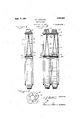
- FIG.1 isan edge View of a wheel embodying the invention parly in elevation and partly in section;
- Fig. 2 is a fragmentary view showing the end of the hub construction
- Fig. 3 is a view similar to Fig. 1 of a plural tired wheel;
- Fig. 4 is a view similar to Fig. 1 of a single tired wheel but with a modified form of disk construction
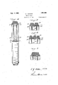
- Fig. 5 is a fragmentary view showing a section through thetire rim and adjacent disks ofthe form of wheel shown in Fig. 4, but with duplex tires;
- Fig. 6 is a view similar to Fig. 5 but with triplex tires
- I Fig. 7 is a view similar to Figs. 5 and 6, but with a different arrangement of disk securing and tire re-enforcing annular members.
- the usual tire comprising the metal tire band 1 and the rubber tire 2 has placed within it the dished metal plates or disks 3 and 1, the concave surfaces being inward and the convex surfaces outward.
- These plates slide with an easy fit into the band 1 and are held therein by the annular rings 5 and 6 of L-shaped. or right angle cross section.
- These rings 5 and 6 are forced into the band 1 by hydraulic pressure and act to re-inforce the tire and at the same time hold the disks 3 and 4 securely in place.
- the hub comprises a cylindrical portion 7 fitted within central holes in the disks 3 and 4, and the circumferential flange 8.
- a collar 9 slides upon the portion 7 and may be removed to permit the part 7 to be inserted within the disks.
- the collar 9 may then be applied and bolts 10 inserted and secured whereupon the internal edges of the disks 3 and are securely held betweenthe flanges Sand 9 and also the hub is'secured in position; I k
- A. convenient method of assembling the wheel is to place the tire b and upon the bed plate of a hydraulic press.
- The'ring 5 is then laid thereon, the disks 3 and 4 are laid upon the ring 5 and the ring 6 is laid upon the disks.
- the platen of the press is then moved downwardly forcing the rings 5 and 6', carrying with them the disks 3'and 4, into the tire band until the desired position is reached.
- the hub portions 22 and 23 are constructed and mounted in the disks in a manner as described in connection with Fig. 1.
- metal disks 24 and 25 are c-oncaved inwardly instead of outwardly and are held in position within the tire band 26 by annular rings 27 and 28 of angular cross section which are forced within the band 26 by high hydraulic pressure, the disks being spaced and held' in proper lateral positionwith relation to the. band 26 by means of a ring 29 channelshaped in section.
- the hub may be secured in the disks in the manner as already described in connection with Figs. 1, 2, and 3 inclusive and the parts may be assembled by a hydraulic press in the same manner.
- the tire band 30 is made of sufficient width to accommodate two rubber tires 31 and 32.
- the rings of angular sec tion 33 and 34, the disks 35 and 36 and the ring 37 of channel-shaped section are assembled within the band 30 in a manner as described in connection with Fig. 4.
- this structure being adapted to provide any desired Width of channel that is desired by varying the idth of the band 42an d at the same time securing the characteristics of a channel-shaped structure as shown in Figs.
Landscapes
- Engineering & Computer Science (AREA)
- Mechanical Engineering (AREA)
- Tires In General (AREA)
Description
c. J. DALTON VEHICLE WHEEL Sept. 6 a
2 Sheets-sh t 2 Filed Dec. 13, 1922 I'll: ll
III/I "INVE IfI TOR.
ATTORNIEQ Q Patented Sept. 6, 192?.
melt-3 I set CHARLES J. DALTON, on NEW YORK, N. Y.
VEHICLE WHEEL. I
This invention relates to vehicle wheels particularly those for use on trucks although it may find application in wheels of vehicles of'other character.
The main object of the invention is to provide a device of the character as indicated which shall be simple, inexpensive to construct and strong and efficient in operation.
Other and ancillary objects of theinvention will appear hereinafter.
In the accompanying drawings which illustrate the invention Fig.1 isan edge View of a wheel embodying the invention parly in elevation and partly in section;
Fig. 2 is a fragmentary view showing the end of the hub construction Fig. 3 is a view similar to Fig. 1 of a plural tired wheel;
Fig. 4 is a view similar to Fig. 1 of a single tired wheel but with a modified form of disk construction;
Fig. 5 is a fragmentary view showing a section through thetire rim and adjacent disks ofthe form of wheel shown in Fig. 4, but with duplex tires;
Fig. 6 is a view similar to Fig. 5 but with triplex tires; and I Fig. 7 is a view similar to Figs. 5 and 6, but with a different arrangement of disk securing and tire re-enforcing annular members.
Referrinv to the drawings and first to Figs. 1 and 2 the usual tire comprising the metal tire band 1 and the rubber tire 2 has placed within it the dished metal plates or disks 3 and 1, the concave surfaces being inward and the convex surfaces outward. These plates slide with an easy fit into the band 1 and are held therein by the annular rings 5 and 6 of L-shaped. or right angle cross section. These rings 5 and 6 are forced into the band 1 by hydraulic pressure and act to re-inforce the tire and at the same time hold the disks 3 and 4 securely in place. The hub comprises a cylindrical portion 7 fitted within central holes in the disks 3 and 4, and the circumferential flange 8. A collar 9 slides upon the portion 7 and may be removed to permit the part 7 to be inserted within the disks. The collar 9 may then be applied and bolts 10 inserted and secured whereupon the internal edges of the disks 3 and are securely held betweenthe flanges Sand 9 and also the hub is'secured in position; I k
A. convenient method of assembling the wheel is to place the tire b and upon the bed plate of a hydraulic press. The'ring 5is then laid thereon, the disks 3 and 4 are laid upon the ring 5 and the ring 6 is laid upon the disks. The platen of the press is then moved downwardly forcing the rings 5 and 6', carrying with them the disks 3'and 4, into the tire band until the desired position is reached. V Q
Referring now .to Fig. 3, a wheel of sufficient width to accommodatethe two tires 11 interior structure of the wheel of Fig. 1,
namely the rings 14 and 15 of angular cross section and the dished disks 16 and 17 and the similar structure composed of the rings 18 and 19 and the disks 20 and 21 are forced by hydraulic pressure within the ring 13 in with Fig.1. The hub portions 22 and 23 are constructed and mounted in the disks in a manner as described in connection with Fig. 1.
Referring now to Fig. 4: metal disks 24 and 25 are c-oncaved inwardly instead of outwardly and are held in position within the tire band 26 by annular rings 27 and 28 of angular cross section which are forced within the band 26 by high hydraulic pressure, the disks being spaced and held' in proper lateral positionwith relation to the. band 26 by means of a ring 29 channelshaped in section. The hub may be secured in the disks in the manner as already described in connection with Figs. 1, 2, and 3 inclusive and the parts may be assembled by a hydraulic press in the same manner.
In Fig. 5 the tire band 30 is made of sufficient width to accommodate two rubber tires 31 and 32. The rings of angular sec tion 33 and 34, the disks 35 and 36 and the ring 37 of channel-shaped section are assembled within the band 30 in a manner as described in connection with Fig. 4.
A similar construction is shown in Fig. 6 except that the tire band 38 is made broad ene'u h to accommodate the. three rubber.
to n.
a'manner as already described in connection In the structure shown in Fig. 7 the manner of assembling the structure is the same as shown in Fig. 4 except that in place of the ring of channeled section as shown in Fig. 4 there is employed between the disks an annular band 42 Within which are forced the rings 43 and 44 of angular cross section,
this structure being adapted to provide any desired Width of channel that is desired by varying the idth of the band 42an d at the same time securing the characteristics of a channel-shaped structure as shown in Figs.
. 4 to. 6 inclusive.
While the invention has been illustrated in What is considered itsbest applications it may have other embodiments Without de parting from its spirit as embraced by the tional en 'a 'ement for se'curin said central t u i o c o I I i l b portion to, said run on one side and means on the other side of said central portion for securing said central ortion insaid rim,
2. In a vehicle ivhee the combination with a rim, of a disl ra-ndmeans forced Within said rim, and'held therein by frictional engagement, for securing said disk and another. disk secured in said rim.
In a vehicle Wheel the combination with a rim, of a central portion and an annular member forced Within said rim, and held therein by frictional engagement, for secur- 111 said central portion to said rim on one side and means on the othersice: of said central portion for securing said central pora rim, of a plurality of disks and annularv X. l 4 V members rorced W thin said rim at the outer Within said rim.
6. The combination with a rim, of and)- ber tire mounted thereon, a pair of concave disks Within said rim and annu'l ar members forced Within said rim outside said disks for securing said disks within said rim-, and a hub portio'n secured tosz iid disks. l
7. The combination Wit-ha rim, of a rubberiire mounted thereon, a pair of concave disks Within said lfllll, annular spacing lnQtlllS Wlthl-H said disks and annular members forced Within said rim outside said disks for securing said disksfwithiii said rim, and a hub portion secured to. said disks.
in testimony whereof 'I have signed this specification this 22nd day of September,
sides of said -disks for, securing said disks misses i. DALTON.
Priority Applications (1)
| Application Number | Priority Date | Filing Date | Title |
|---|---|---|---|
| US606572A US1641663A (en) | 1922-12-13 | 1922-12-13 | Vehicle wheel |
Applications Claiming Priority (1)
| Application Number | Priority Date | Filing Date | Title |
|---|---|---|---|
| US606572A US1641663A (en) | 1922-12-13 | 1922-12-13 | Vehicle wheel |
Publications (1)
| Publication Number | Publication Date |
|---|---|
| US1641663A true US1641663A (en) | 1927-09-06 |
Family
ID=24428510
Family Applications (1)
| Application Number | Title | Priority Date | Filing Date |
|---|---|---|---|
| US606572A Expired - Lifetime US1641663A (en) | 1922-12-13 | 1922-12-13 | Vehicle wheel |
Country Status (1)
| Country | Link |
|---|---|
| US (1) | US1641663A (en) |
Cited By (2)
| Publication number | Priority date | Publication date | Assignee | Title |
|---|---|---|---|---|
| US6820942B1 (en) * | 2003-03-04 | 2004-11-23 | Sammy K. Knaak | Dual non-inflatable wheel assembly for trucks |
| EP3162592A1 (en) * | 2015-10-26 | 2017-05-03 | Sumitomo Rubber Industries, Ltd. | Airless tire |
-
1922
- 1922-12-13 US US606572A patent/US1641663A/en not_active Expired - Lifetime
Cited By (3)
| Publication number | Priority date | Publication date | Assignee | Title |
|---|---|---|---|---|
| US6820942B1 (en) * | 2003-03-04 | 2004-11-23 | Sammy K. Knaak | Dual non-inflatable wheel assembly for trucks |
| EP3162592A1 (en) * | 2015-10-26 | 2017-05-03 | Sumitomo Rubber Industries, Ltd. | Airless tire |
| US10189311B2 (en) | 2015-10-26 | 2019-01-29 | Sumitomo Rubber Industries, Ltd. | Airless tire |
Similar Documents
| Publication | Publication Date | Title |
|---|---|---|
| US1710614A (en) | Tire rim | |
| US1641663A (en) | Vehicle wheel | |
| US2354439A (en) | Method of making disk wheels | |
| US2150111A (en) | Method of making wheel structures | |
| US2167102A (en) | Wheel | |
| US2624635A (en) | Wheel cover | |
| US2279330A (en) | Ornamental trim ring for wheels | |
| US1769296A (en) | Dual wheel structure | |
| US2148658A (en) | Vehicle wheel | |
| US1390893A (en) | Antiskidding device | |
| US1415427A (en) | Vehicle wheel | |
| US2502060A (en) | Emergency wheel for vehicles | |
| US1577158A (en) | Demountable rim structure for wheels | |
| US2014811A (en) | Vehicle wheel | |
| US1396984A (en) | Resilient wheel | |
| US1583222A (en) | Wheel for industrial trucks | |
| US2411164A (en) | Wheel structure | |
| US1004582A (en) | Tire for vehicle-wheels. | |
| US1560756A (en) | Locking ring for separable rims | |
| US1417724A (en) | Sectional rim for pneumatic tikes | |
| US1514864A (en) | Rim for vehicle tires and wheels | |
| US1948324A (en) | Wheel and method of making it | |
| US1491748A (en) | Auto rim | |
| US1177459A (en) | Vehicle-wheel rim. | |
| US1159313A (en) | Vehicle-wheel. |