US1623402A - Pump and internal-combustion engine therefor - Google Patents
Pump and internal-combustion engine therefor Download PDFInfo
- Publication number
- US1623402A US1623402A US412154A US41215420A US1623402A US 1623402 A US1623402 A US 1623402A US 412154 A US412154 A US 412154A US 41215420 A US41215420 A US 41215420A US 1623402 A US1623402 A US 1623402A
- Authority
- US
- United States
- Prior art keywords
- cylinder
- piston
- engine
- chamber
- pump
- Prior art date
- Legal status (The legal status is an assumption and is not a legal conclusion. Google has not performed a legal analysis and makes no representation as to the accuracy of the status listed.)
- Expired - Lifetime
Links
- 238000002485 combustion reaction Methods 0.000 title description 21
- 239000000446 fuel Substances 0.000 description 24
- 239000007789 gas Substances 0.000 description 19
- 239000012530 fluid Substances 0.000 description 17
- 230000006835 compression Effects 0.000 description 11
- 238000007906 compression Methods 0.000 description 11
- 239000002360 explosive Substances 0.000 description 11
- 239000000203 mixture Substances 0.000 description 11
- 239000003921 oil Substances 0.000 description 7
- 241001052209 Cylinder Species 0.000 description 4
- 238000010276 construction Methods 0.000 description 4
- 230000005484 gravity Effects 0.000 description 3
- 230000035939 shock Effects 0.000 description 3
- 238000004880 explosion Methods 0.000 description 2
- 238000005381 potential energy Methods 0.000 description 2
- 101100116570 Caenorhabditis elegans cup-2 gene Proteins 0.000 description 1
- 206010010071 Coma Diseases 0.000 description 1
- 101100116572 Drosophila melanogaster Der-1 gene Proteins 0.000 description 1
- 101100001672 Emericella variicolor andG gene Proteins 0.000 description 1
- 241000792859 Enema Species 0.000 description 1
- 235000006629 Prosopis spicigera Nutrition 0.000 description 1
- 240000000037 Prosopis spicigera Species 0.000 description 1
- 208000003443 Unconsciousness Diseases 0.000 description 1
- 230000000295 complement effect Effects 0.000 description 1
- 239000007920 enema Substances 0.000 description 1
- 229940095399 enema Drugs 0.000 description 1
- 239000000295 fuel oil Substances 0.000 description 1
- 230000006870 function Effects 0.000 description 1
- 238000009434 installation Methods 0.000 description 1
- 238000013021 overheating Methods 0.000 description 1
- 230000008439 repair process Effects 0.000 description 1
- 230000002000 scavenging effect Effects 0.000 description 1
- 238000009331 sowing Methods 0.000 description 1
Images


Classifications
-
- F—MECHANICAL ENGINEERING; LIGHTING; HEATING; WEAPONS; BLASTING
- F02—COMBUSTION ENGINES; HOT-GAS OR COMBUSTION-PRODUCT ENGINE PLANTS
- F02B—INTERNAL-COMBUSTION PISTON ENGINES; COMBUSTION ENGINES IN GENERAL
- F02B75/00—Other engines
- F02B75/28—Engines with two or more pistons reciprocating within same cylinder or within essentially coaxial cylinders
- F02B75/30—Engines with two or more pistons reciprocating within same cylinder or within essentially coaxial cylinders with one working piston sliding inside another
-
- F—MECHANICAL ENGINEERING; LIGHTING; HEATING; WEAPONS; BLASTING
- F02—COMBUSTION ENGINES; HOT-GAS OR COMBUSTION-PRODUCT ENGINE PLANTS
- F02M—SUPPLYING COMBUSTION ENGINES IN GENERAL WITH COMBUSTIBLE MIXTURES OR CONSTITUENTS THEREOF
- F02M59/00—Pumps specially adapted for fuel-injection and not provided for in groups F02M39/00 -F02M57/00, e.g. rotary cylinder-block type of pumps
-
- F—MECHANICAL ENGINEERING; LIGHTING; HEATING; WEAPONS; BLASTING
- F02—COMBUSTION ENGINES; HOT-GAS OR COMBUSTION-PRODUCT ENGINE PLANTS
- F02M—SUPPLYING COMBUSTION ENGINES IN GENERAL WITH COMBUSTIBLE MIXTURES OR CONSTITUENTS THEREOF
- F02M2700/00—Supplying, feeding or preparing air, fuel, fuel air mixtures or auxiliary fluids for a combustion engine; Use of exhaust gas; Compressors for piston engines
- F02M2700/13—Special devices for making an explosive mixture; Fuel pumps
- F02M2700/1317—Fuel pumpo for internal combustion engines
Definitions
- the invention has for an object to provide-van engine, preterably of the lnternal combustion type, which may be operated to produce very small amounts of power, which will run at a low operating cost and with verylittle attention and repairs,
- Such an engine may be use'd, for example,to furnish the power for small domestic refrigerating machines when electric power is'not avail-. 1o able, the unusual demands of which device.
- w ll be apparent when it-is considered thatv only about one-fifteenth (1/15) horsespower is required toyield the equivalent of one hundred and fifty pounds (150 lbs.) of ice per g day.
- the engine should be capable of running for long periods without requiring ad ustments or IQPHIISfOI' frequent attention.
- the invention also-includes simple and re-' 'liablefuel feeding andscavenging devices suitable for an engine of the above character.
- Another object of the invention is to combine such an engine with afluid pump so as -to form a rugged, compact construction whiclrcannot be'readily injured, which is 1111 318 in installation and operation and in which the fluid pressures produced by, the
- .30 pump are suitably controlled during operation otthe engine.
- Fig. is a vertical, sectional view'of portion of the engine piston and cylinder
- Fig. t is aview showing the engine cylin der within its casing, the latter appearing n section Fig. 5 is a vertical, sectional view-of the.
- the engine comprises generally a movable member of comparatively large weight, which is urged towarda' position at rest, in suchmanner that the expansive force of the fluid within the engine cylinder, moves said weight against the action of the force which tends to maintain it in its position at rest, and thus impartsenergy to the movable member.
- the cylinder 1 ofthe' engine is utilized as the movable member vof large weight, and such cylinder is slidable upon a plurality of guides 2 extending from.
- the cylinder isprovided with upper and lower flanges 5 and 6, respectively, having bearings 7 and 8, respectively, for receiving the guides 2, so that the cylinder'may slide freely upiand down thereon.
- the piston 9 ottheengine is slidably mounted within the cylinder 1 previously described, and in the present form, not only 35 does the cylinder 1 move upwardly, but the piston 9 moves upwardly withit as soon as the cylinder has moved upwardly a dis tance equal to the travel permitted between the cylinder and piston. I 7 f
- the piston is utilized to bring the cylinder to rest.
- the piston comes into engagement with the base 3 .off the ap parat-us, so that the cylinder l is brought shown (see Fig. 3), the pi'stonl9 slides over.
- ablockll suitably supported from thecylinder 1,ior instance, by a. pair of pins 12 passing through'thc. cylinder and block and; through slots 13 in the walls of the piston. Vith a construction of this nature, 'whenf the piston and cylinderapproach the'ends f v of their paths of relative travel, a cushion-.-
- the fluid pressure witlnnthe pump harrel 16 is released after cylinder' -1 has moved downwardly on its return movement fora predetermined distance, so that the remainingtall of the cylinder is'practicelly" unimpeded except for the work done in com-r pressing the'g'asl Figs. 1i and 2 show a simple arrangement adapted to perform this function i
- a sleeve valve 25 connectedto u forked arm 26 slides over the end of a pipe 2'2, having one or more openings 28 which communicate with the reservoirlt' when the" ion sleeve-25 is in elevated position.
- the motion of the movable. member of the engine ' may be ut l'iz'ed; to.
- An enclosing housing or casing 34 may also be provided for the cylinder l'to fflCllltatC thescavenging action.
- the flanges 5 andG are disposed on opposite sides of the cylinder 1 and respectively adjacent one-or more of the v ports 33, and a plurality of longitudinal ribs 35 on cylinder 1' e'Xtend'b-etweeii theflanges or bafiie platesy5-and 6 in such a way as to divide the space within casing 34 into a pair of chambers 36 and 37 (Fig. 4), the chamber 36 being located in general abovethe chamber 37.
- Exhaust openings 38 may be located in the walls of the casing 34 at such an elevation that they will be substantially oppositeto'theports 33 at the time when the exhaust of the engine taking place, thus permitting the fbulk of the exhaust gases to pass out from within casing 34.
- the engine illustrated: is also designed to time.
- the cylinder head 40 contains a fuel supply reservoir 41,
- valve 45 which may be replenished from time to time in any desired manner, there'being a duct 42 (Fig. 5) leading from said reservoir to achamber 43 separated from the cylinder chamber 4 by a valve 45.
- the valve 45 is carried upon a valve rod 46, the latterbeing resiliently urged to move the. valve 45 to closed position, for instance by a coil spring 47, hearing against adisk 48 on theIend: of
- Wl'llCil collar may be moved by an'adjusting screw 50 to vary the pressure of the spring.
- valve rod 46 is surrounded by a sleeve pump 51'provided with suitablepacking 52, and connected to a weight 53 within the fuel supply reservoir 41.
- a spring 54' lies beneath the. sleeve pump 51 and under normal conditions presses up on the latter to a 'suf ficient extent to hold weight 53 up against a:
- valve 58 carried by a valve-rod 59
- valve-rod 59 may also be employed to shut off connection between the duct 42'and thefuel supply reservoir at the time when valve 45 is open.
- this valve'rod 59 fixed to a weight 60 located within a recess 61,in weight 53 previously described, a complementary recess 61 being provided to balance weight 53- properly about its.
- a coil spring'62 bears upwardly upon the weight- 60 with suflicient' force tomaintain the valve 58 elevated from its seatunder normal conditions insuchmanner that the fuel may flow from supply'reservoir 41 through bypass 42 to the ducti42.
- spring 62 beco'mes insufficient to hold up valve 58 against the inertia EtCtlOll'Of weight 60, with theresult that valve 58-closes at the same time that.
- valve 45 opens, permitting suificient pressure lll 'i to be brought about/in chamber 43 to inject the fuel into the cyliiiderchamber 4.
- valve 58 again opens, and weight 53 and sleeve pump] 51 are elevated by spring 54, with the result that valve 45 closes, and more fuel runs intofuel pump chamber 43.
- the engine is'stoppedby closing the valve in delivery pipe 22 (Fig. 1 which causes heavy cylinder 1 to'm'ove downwards very slowly (due only to'lea-kage of oil from pumpbarrel '16) so that a"rod, or other suitable tool, may be'thrust into casing 34 underneath the heavy cylinder I to bring the latter to a 'deadistoplinan" elevated position, Without undue shock ⁇ henthe' engine has been stopped as above *5"- stated,to startit,itfis only necessary to remove the rod hich supports the heavy cylin- 1 L If the engine should stop becausefofjex haustion 0t fuel supply, the heavy. cylinder 7 will come'torest in extremeloyverposition. Tostart the engine under these condltions,
- Tl e'engine may also bereadily "operatedto ,supplybut very littleamounts hot-power since the distance the, movable nemberol' the engine ismoved maybe-reguof energy Will beldeliveredtofior givenup itlierebyx I i
- The'engine increases the dash pot eflect of compressiom jand stops the fallingfcylinder more prickly norneed. thezstroke of V the engine be exactly constant;- and if an unusually high compression irisxdeveloped vvithin the cylinder, it
- V cylinder due. to its heavy and strong, constructlon, nerds overheating of the cylinder ;tion*has,;been described, it-is obvious that many changes may be, m ade wvithout departcombustion engine having members beingslidablyijcarried the other move the piston relative to the cylinder member and both of said members relative to said fixed abutment to lmpart energy to said members, and .meansfor ut1l z1ng:en-
- An internal combustion engine having piston and cylindermembers, one of said i members being slidably cajrriedby the other and-being constantly urged by aconstantly acting force toward a position against a fixed abutment, the other member being also slidably mounted, means vfor supplying an explosive m xture Within said chamber to move the piston relative to the cylinder member and, both of said'members relat1veto said fixed abutment to impart energy to s ai'd'members, means for utilizingthe energy thus imparted to said members to perform useful Work, and, .aportion of the return movement of said members to compress fresh gas ⁇ Vltllll'l' the cylinder chamber.
- An internal combustionengine having piston and cylinder]members, one-of said members being slida'bly carried by the other and being constantly lurge'dby a constantly acting force toward "a position againsta fixed abutment, the otherinember being also. 7
- a piston carried by said cylinder and slidable toa limited extent with regard thereto, said piston engaging said base when the cylinder s in lower position, means for supplying an explosive mixture to the cylinder chamber to elevate said cylinder, and means for utilizing the potential energy thus imparted to the cylinder, to perform useful work.
- An internal combustion engine having a fixed base, a cylinder mounted to slide up and down thereon, a piston carried bysaid cylinder and slidable to a limited extent with regard thereto, said piston engaging said base when the cylinder is in lower position, means for supplying an explosive mix ture to the cylinder chamber to elevate said cylinder, and means for utilizing-the return movement of the cylinder to perform useful work and compress-a fresh charge of gas 8.
- An internal combustion engine having a fixed base, a cylinder mounted to sildeup and down thereon, a piston carried by sa1d cylinder and slidable to a limited extent with regard thereto, said piston engaging said base when the cylinder is in lower position, means for supplying an explosive mixture to the cylinder chamber toelevate said cylin der,.means for utilizing the initial portion" of the return movement of the cylinder to perform useful work, and the latter portion of such movement to compress a fresh charge of gas within the cylinder chamber, and
- Afuel feeding device for internal combustion engines comprising a weight moving in general with the main movable member of the engine but yieldably supported therefrom, a valve between the fuel supply and the cylinder chamber, and means where-:
- a fuel feeding device for internal combustion engines comprising a valve adapted to close communication between an oil pump chamber and the engine cylinder chamber, a weight moving in general with the main movable member of theengine but yieldably supported therefrom, an oil pump associated with said pump chamber, and
- a fuel feeding combustion engines comprising a main movdevice for internal able member for the engine having afuelf pump chamber therein, a valve rod-passing through said chamber urged to close communication between the pump chamber and i V the cylinder chamber, and a fuel pumpcomprising a reciprocable sleeve surrounding saidvalve rod and a Weight y eldably sup ported by the movable member connected to said sleeve, whereby the inertia .actionof said'weight will operate said sleeve to move the valve rod and force fuel into the cylinder chamber and draw further fuel into the pump chamber when the rate of motion of the movable member is retarded and acceler-I Y atedh I Y r 13.
- a fuelfeedin-g device for internal comg bustion eng nes comprising a mainmovable member for the engine having a fuel reservoir and a fuel pump chamber therein with a fuel duct'leading therebetween, a weight moving in general with said movable mem-.
- An internalicombustin engine having-- a heavy, movable member associated therewith and urgedtoward one position by a constantly acting force, means for supplying an explosive mixture within the cylinder chamber to move said member againstthe action of said force'to another position, means for, utilizing the energy imparted to said member to perform useful work and 'a portion of the return movement of said member to compress fresh gaswithin the cylnider chamber, a weight yieldably supported byf'said movable member, and means operated by the inertia action of said weight for feeding fuel to the cylinder chamber-during compression "of gas within the" cylinder ch r I 15.
- V '16 engine"havingjr-elatively.
- movable v cylinder ⁇ and piston members the piston i b eing ho'llow, and a block located Within jthelpistonfand supported from the cylinder adapted to co-operate with the head of the H i'piston ftoiform avcushioning poc-ket for the I I jlative ,movement between the piston and V der.
- transverse baffle-plates 10- cated respectively above and below said exhaust portsand-extending between the movable-member and portions of the casing" Wall adjacent said ports, and longitudinal ribs com-iecting said bafli-e-plates 'to di'videj the space between the movable member and the casing 'into separate air chambers,
- an internal combus tion engine comprising relatively slidable cylinder and piston members, .theslidable member being constantly urged toward the other member bya constantly acting force
- bustion engine com-prisinga heavy cylinder mounted tov slide. up and down above said base member, a piston slidably mounted vithin said cylinderg said piston being engageable with said base, whereby further 7 downward movement 0% the cylinder when the piston is so engaged will compress gas within said cylinder, means for supplying anexplosive mixture Within the cylinder chamber toelevate the. cylinder, said pump plunger being connected to said piston.
- a base member having a fluid reservoir. and a pump chambertherein and vertical pump plunger working within said chamber, and an internal combustion engine comprisinga heavy cylinder mounted 'to" slide up and d'o-Wn'above said base .member, a piston 'slidably mounted .withinsaid cylinder, said piston being ens e gageable with said base, whereby 'turther downward movement of -.the* cylinder when the piston is so engaged will compress gas within said cylinder, means for supplying an explosive mixture within the cylinder 7 means for opening communication between chamber to'elevate t Cylinder; said P i Q 1 plunger being connected to said" P and l the fluid reservoir and pump chamber substantially when the piston is in engagement with the base.
- An engine comprising relatively movable piston and cylinder members, the movable member being urged toward the other member by a constantly acting force, means for producing gaseous pressurewithin said cylinder to actuate the 'movable member away from the other member, and means operable during each stroke of the movable member for exhausting the gases from with-.
- An engine comprising relatively movable piston and cylinder members, the movable member being urged toward the other member by a constantly acting force, means for producing gaseous pressure within said cylinder to actuate the movable member away from the other'member, means operable during each stroke of the movable memher for exhausting the gases. from wlthln the cylinder and admitting afresh charge of gas thereto while the movable member is near the outer limit of its travel away from the other member, and means for utilizing the energy imparted to said member to perform useful work and a portion of the return movement of said member to vcompress fresh gas within the cylinder chamber suificiently to produce ignition thereof.
- An engine comprising relatlv-ely movable piston and cylinder members, the movable member being urged toward the other member by constantly acting force, means for producing gaseouspressure withln sald cylinder to actuate the movable member member by a constantly acting force and. belng variable as regards its length of stroke, I
- the cylin der having a port therein adapted to be uncovered by the piston when the members are near the outer limit of movement relative to each other whereby the gases within the cylinder may be exhaust-ed, means for supplying a fresh charge of gas through said port also when the members are near the outer limit of movement relative to each other on thereturn movement, said abovementioned force acting during the r-eturn' movement of-the movable member to compress the fresh charge suiiiciently to produce ignition thereof.
Landscapes
- Engineering & Computer Science (AREA)
- Chemical & Material Sciences (AREA)
- Combustion & Propulsion (AREA)
- Mechanical Engineering (AREA)
- General Engineering & Computer Science (AREA)
- Output Control And Ontrol Of Special Type Engine (AREA)
Description
5 shecs sheet 1 w. s. FRANKLIN PUMP .AND INTERNAL COMBUSTION ENGINE THEREFOR Filed Sept. 23, 1920 April 5; 1927.
April 5, 1927.
w. s. FRANKLIN PUMP AND INTERNAL COMBUSTION ENGINE THEREFOR v 5 Sheets-Sheet 2 Filed Sept. 23 1920 I 1,623,402 7 P" w. S. FRANKLIN PUMP AND INTERNAL COMBUSTION ENGINE- THEREFOR- Filed Sept. 23. 1920 5 Sheets-Sheet s April 5-, 1927.
W. S- FRANKLIN PUMP Mm INTERNAL COMBUSTION ENGINE THEREFOR Filed S ep t. 25. 1920 5 Sheets-Sheet 4' Ap 5' 1927? w; s. FRANKLIN.
PUMP AND INTERNAL COMBUSTION ENGINE TflEREFOR.
Filed se tfzs'. 1920 6 Sheets-Sheet s Patented Apr, 5, 192?] were [stars e er 'WILLIAM S. FRANKLIN, OF CAMBRIDGE, MASSACHUSETTS.
rum? nun rnrnnnan-comsusrron Enema Tnnanron;
Application filed September 23, 1920. Serial No. 412,154.
The inventionhas for an object to provide-van engine, preterably of the lnternal combustion type, which may be operated to produce very small amounts of power, which will run at a low operating cost and with verylittle attention and repairs, Such an engine may be use'd, for example,to furnish the power for small domestic refrigerating machines when electric power is'not avail-. 1o able, the unusual demands of which device. w ll be apparent when it-is considered thatv only about one-fifteenth (1/15) horsespower is required toyield the equivalent of one hundred and fifty pounds (150 lbs.) of ice per g day. Itwill also be obvious that, to be suitable for such service, the engine should be capable of running for long periods without requiring ad ustments or IQPHIISfOI' frequent attention.
The invention also-includes simple and re-' 'liablefuel feeding andscavenging devices suitable for an engine of the above character. V I
Another object of the invention is to combine such an engine with afluid pump so as -to form a rugged, compact construction whiclrcannot be'readily injured, which is 1111 318 in installation and operation and in which the fluid pressures produced by, the
.30 pump are suitably controlled during operation otthe engine.
Further objects and advantages of the invention will be in part obvious and in part specifically pointed out in the description as hereinaftercontained, 111 which is disclosed one embodiment of the invention; such embodiment, however, is to be considered voir shown at the bottom. of Fig. 1", with v its cover-plate removed; 1
Fig. is a vertical, sectional view'of portion of the engine piston and cylinder,
showing the connection between the'two;
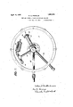
-" I Fig. t is aview showing the engine cylin der within its casing, the latter appearing n section Fig. 5 is a vertical, sectional view-of the.
cylinder head showing particularly the fuel feeding devices carried thereby. V
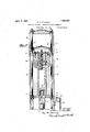
The engine comprises generally a movable member of comparatively large weight, which is urged towarda' position at rest, in suchmanner that the expansive force of the fluid within the engine cylinder, moves said weight against the action of the force which tends to maintain it in its position at rest, and thus impartsenergy to the movable member.
In the embodiment shown in the accompanying drawings,the cylinder 1 ofthe' engine is utilized as the movable member vof large weight, and such cylinder is slidable upon a plurality of guides 2 extending from.
a base member 3 for the combined pump and 7 engine. Thus the action of gravity in the v present instance, constantly urges theicylin der 1 toward the base member 3, andthe' energy'imparted to the cylinder 1 through the action of an expansive fluid within the cylinder chamber 4, may be utilized-to perform useful work; In the present instance,
the cylinder isprovided with upper and lower flanges 5 and 6, respectively, having bearings 7 and 8, respectively, for receiving the guides 2, so that the cylinder'may slide freely upiand down thereon. :The piston 9 ottheengine is slidably mounted within the cylinder 1 previously described, and in the present form, not only 35 does the cylinder 1 move upwardly, but the piston 9 moves upwardly withit as soon as the cylinder has moved upwardly a dis tance equal to the travel permitted between the cylinder and piston. I 7 f Upon downward movement of the. cylinder (and piston, it the latter isconstructed to move therewith), the piston is utilized to bring the cylinder to rest. 1 In the present form,'the lower head-10 01": the piston comes into engagement with the base 3 .off the ap parat-us, so that the cylinder l is brought shown (see Fig. 3), the pi'stonl9 slides over.
ablockll suitably supported from thecylinder 1,ior instance, by a. pair of pins 12 passing through'thc. cylinder and block and; through slots 13 in the walls of the piston. Vith a construction of this nature, 'whenf the piston and cylinderapproach the'ends f v of their paths of relative travel, a cushion-.-
' r ts pot 14' filled; for example, with oil mayalso; 'b'eplaced between the bascg and the cylin def-head of thcpiston in order to relieve undue shocks. when the piston head comes v 1 'o i the piston- 'lcombustion typejand, it it-is assumed that 1 positions with the pistonhead 10 against the fbase "'3 and an explosivegaseous mixture suitably ignited withnrthe cylinder chamber I the cylinder "1. against the action of'gravity untillthas traveled upward at distance equalcertainff orinsof which will he later de- Theo llinder and piston then travel down if piston head 10 comes into engagement with the lloase Sfttfterwlnch furtherdownward xtruvelflofthe cylinder compresses the an f wjithi n thefcylinderchamber and theengine is ready for a repetition of the cycle; t Inth e'apparatus' illustrated the motion 1m- -'-operate' t fluid puin'pgjefor exampleof the type employed 7 to operate the diaphragm compressors used in refrigerating machines. The pump plunger reciprocates 7 within thejpinnpbarrel' 16' (see'hottonrot Fig-. 1")
1 mem r 3 on n a e oir r y s the fluid to he pumpedand the plunger 15 ifslids within ah'ollow' post 18' bolted to the fbottom of the reservoir 17, andhuving an annular chamber 19 "communicating. with the, pump harrel fld g The 'puinp plunger suitablyconngctedwiththe movable v "niemberiof .the e'ngine, being shown in the structureillustratedas bolted to hlockll (see Fig. 3), so that it follows the movepuinp herrel 16' through an inlet checlcvalve 20-ofsuitahle construction (Fig.2) connect ed-tothe;annular ehamloer'lQ hyineans ota i Q; of 'the' cylinder and phinger begins check V to absorb aliy shocks which otherwise mightbedeveloped between the members. f A dash aoainstthe base after. downward movement 7 x v V f ceed ng a predetermined amount. For this The en ine is; preii'erahly of the internal, purpose rehetvelve 23 2), thestruc a theeylinderand piston he at theirflowest 4, the force ofthe explosion will first raise 'to therelative travel permitted between the Toylinder and'i'piston; the inoinentuinotthe cylinder will then carry the latter and also i ,C hiirgefif air supplied by" suitable 'means,;
"wardly iinder the action otgravity until the parted to "the heavy cylinderi' is utilized to? theflatter being associated with the hose member 3 (seeFi'g. 1 *As shown, the base ment; ofthe-fheev-y}oylinderl. In" the pres- V ent fornithe. working. stroke of the plunger 15 occurs during the downward fallof the cylinder 1,1andas the cylinder moves upward- 1y carrying the plunger 15 withj it, the fluid to; V i
Q he pumped: is drawn from reservoir 1". into I upward movement I of thefcylinder 1, and
after the piston and cylinder have justahout reached; the end of their travel relative to.
pipe} 21. WZhen the; downward movement iorce fresh air into the cylinder chamber valve 20 closes such to operate 3, dia. hra 'in coinoressor i B l. 7
it is desirable to control the pressure of the oil or liquidpulnped to prevent' t irom extureofwhichit is notfdeemed necessary to In order to facilitate proper compression descrihe'in detail, inay'he employed so usto permit the fluid pumped to flow back into reservoir 1'? when a certain pressure is ex 'ceeded; e i r f the fresh as to be em; )lfo ed in the suc- V b l V :ceeding cycle of the engine, the engine may also be released from its load during the portion ot the return stroke inwhich compression of the gas takes place. 7 In the present'torm, the fluid pressure witlnnthe pump harrel 16 is released after cylinder' -1 has moved downwardly on its return movement fora predetermined distance, so that the remainingtall of the cylinder is'practicelly" unimpeded except for the work done in com-r pressing the'g'asl Figs. 1i and 2 show a simple arrangement adapted to perform this function i A sleeve valve 25 connectedto u forked arm 26 slides over the end of a pipe 2'2, having one or more openings 28 which communicate with the reservoirlt' when the" ion sleeve-25 is in elevated position. A. coil spring 29, however, normally maintains the. sleeve valve closed, but after the cylinder 1' hasmoved downwardly a certain distance a rocker a-rm 30 carried by abracket '31 is en gaged by the surface of the cylinder and lifts e rod 32 connected to thearin 29, thus 'open- J to flow back into reservoir 17 during the res hes come into engagement with base 3, to
111g valve25 and permitting the oil'or fluid iii: '5
any substantial extent. 'lVhenthe cylinder rises again, coilspring 29 returns valve 25 'to'closed position'es soon asthe cylinder passes above rocker arm- 30;
If desired the motion of the movable. member of the engine 'may be ut l'iz'ed; to.
eff
act proper eihaust and scavenging of'the "'der chamber 4, without materially addto the structure of the engine. As shownir. Figs/1 and l, cylinderlmay he p ovided i which are uncovered lay-piston 9=dur with-a pluralitv of exhaust ports through ports 33after. the exhaust gases have passed out. An enclosing housing or casing 34 may also be provided for the cylinder l'to fflCllltatC thescavenging action. In the present form the flanges 5 andG are disposed on opposite sides of the cylinder 1 and respectively adjacent one-or more of the v ports 33, and a plurality of longitudinal ribs 35 on cylinder 1' e'Xtend'b-etweeii theflanges or bafiie platesy5-and 6 in such a way as to divide the space within casing 34 into a pair of chambers 36 and 37 (Fig. 4), the chamber 36 being located in general abovethe chamber 37. Exhaust openings 38 may be located in the walls of the casing 34 at such an elevation that they will be substantially oppositeto'theports 33 at the time when the exhaust of the engine taking place, thus permitting the fbulk of the exhaust gases to pass out from within casing 34. As the cylinder 1 then moves upwardly, the flanges 01" battle plates 5 and 6 will produce a certain amount of air pressure within the chamber 36 and rarefaction"within the chamber 37. A. draught of fresh air for the next explosion ,of the engine will therefore pass intolthe cylinder chamber 4 through such ports as are in coinn'iunication-with the chamber36, and will passout of the cylinder chamber througl'i such ports as are'in communication with the chamber 37 so as to thoroughly scavenge the cylinder chamber. 7 If desired, holes 39 may be provided adjacent the upper or lower ends of the casing 34, to; prevent,
such draft of air from becoming excessive.
Upon the return movement of the cylinder by gravity, all of the ports 33 willbe closed when piston head 10 engages with base 3,
and compression of-th'e fresh air within the cylinder chan'i'ber will begin.
It is preferred to employ an internal combustion engine of the type wherein ignition of 'tl e'explosive mixture is eifectcd by compression sufficient toraise thetemperature of the explosive mixture to the ignition I point, on account of its simplicity, although it will be obvious that this isnot essential.
' The engine illustrated: is also designed to time.
operateupon fuel oil, and is provided with a simple device forfeeding the oil orother fluid into the cylinder chamber at the proper It is preferred to operate-the fuel feed upon the inertia principle as by a weight moving in general with the main movable member 1 of the engine, but yieldably supported thereby, so that the accelera Jtion of the inovable'inember 1 will cause the,
weight 'tomove relative thereto at. the
proper time to supply fuel to the cylinder chamber. I p
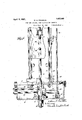
I In the present construction, the cylinder head 40 contains a fuel supply reservoir 41,
* which may be replenished from time to time in any desired manner, there'being a duct 42 (Fig. 5) leading from said reservoir to achamber 43 separated from the cylinder chamber 4 by a valve 45. The valve 45 is carried upon a valve rod 46, the latterbeing resiliently urged to move the. valve 45 to closed position, for instance by a coil spring 47, hearing against adisk 48 on theIend: of
the valve rod at its lower end. and en 'a in r T .b t: a:
acollar49 at its upper end, Wl'llCil collar may be moved by an'adjusting screw 50 to vary the pressure of the spring.
The valve rod 46 is surrounded by a sleeve pump 51'provided with suitablepacking 52, and connected to a weight 53 within the fuel supply reservoir 41. A spring 54' lies beneath the. sleeve pump 51 and under normal conditions presses up on the latter to a 'suf ficient extent to hold weight 53 up against a:
pressure acts upon the shoulder 57 beneath v the valve rod 46, thus raising valve 45 and permitting fuel to be'injected into cylinder chamber 4.
-A further valve 58, carried by a valve-rod 59,"may also be employed to shut off connection between the duct 42'and thefuel supply reservoir at the time when valve 45 is open. In the specific structure shown this valve'rod 59 fixed to a weight 60 located within a recess 61,in weight 53 previously described, a complementary recess 61 being provided to balance weight 53- properly about its.
longitudinal axis. A coil spring'62 bears upwardly upon the weight- 60 with suflicient' force tomaintain the valve 58 elevated from its seatunder normal conditions insuchmanner that the fuel may flow from supply'reservoir 41 through bypass 42 to the ducti42. However, when the downward movement of the cylinder 1 is retarded by compression as previously described, spring 62 beco'mes insufficient to hold up valve 58 against the inertia EtCtlOll'Of weight 60, with theresult that valve 58-closes at the same time that.
The engine is'stoppedby closing the valve in delivery pipe 22 (Fig. 1 which causes heavy cylinder 1 to'm'ove downwards very slowly (due only to'lea-kage of oil from pumpbarrel '16) so that a"rod, or other suitable tool, may be'thrust into casing 34 underneath the heavy cylinder I to bring the latter to a 'deadistoplinan" elevated position, Without undue shock} henthe' engine has been stopped as above *5"- stated,to startit,itfis only necessary to remove the rod hich supports the heavy cylin- 1 L If the engine should stop becausefofjex haustion 0t fuel supply, the heavy. cylinder 7 will come'torest in extremeloyverposition. Tostart the engine under these condltions,
- 32 may bev uncoupled, "sleeve i valve 257 "closed, and the heavy cyllnder raised to 'ele- -v'ated position, after which the rod 32Will ,bythe base member 3', which may be readily "constructed and supported'to resist them adequately. Tl e'engine may also bereadily "operatedto ,supplybut very littleamounts hot-power since the distance the, movable nemberol' the engine ismoved maybe-reguof energy Will beldeliveredtofior givenup itlierebyx I i The'engine increases the dash pot eflect of compressiom jand stops the fallingfcylinder more prickly norneed. thezstroke of V the engine be exactly constant;- and if an unusually high compression irisxdeveloped vvithin the cylinder, it
high pressure incident-tov ignition 'by compression furthermore w ll not lIlJHX'B the ,liabletoroccur, since theengine may operate very slowly wlt h large exposure otcylinder surface. 1 I" V i f I I 'VVhiie a specific-embodiment of the invening from itsvp rinciple as-defined in the folr sowing 'Q aimS? V a .1. 'Anginternal A piston and cylinder members,.cone of said and being constantly urged by a constantly {actingvforoetovvard a position against f fixediabutment, .thefotlier member being also 'sl d a'bly' mounted, means for supplymgan explosiveimixture within sald chamber ito Pd er' l; and open thefvalve in delivery pipe 22.
she reconnected and the heavy cylinder l-Ire' constructed to operate over long periods ot The i'ted"as desiredyso thatonly small amountsf V isalso vvell adapted forigni non by coinplfession', since'preignit onmerely I 3 nierelyactsto accelerate the upivard-movexFmeiitQO-fthe latter w thout .doing any harm;
V cylinder due. to its heavy and strong, constructlon, nerds overheating of the cylinder ;tion*has,;been described, it-is obvious that many changes may be, m ade wvithout departcombustion engine having members beingslidablyijcarried the other move the piston relative to the cylinder member and both of said members relative to said fixed abutment to lmpart energy to said members, and .meansfor ut1l z1ng:en-
ergy thus imparted to said members to perform useful ork;
2. An internal combustion engine having piston and cylindermembers, one of said i members being slidably cajrriedby the other and-being constantly urged by aconstantly acting force toward a position against a fixed abutment, the other member being also slidably mounted, means vfor supplying an explosive m xture Within said chamber to move the piston relative to the cylinder member and, both of said'members relat1veto said fixed abutment to impart energy to s ai'd'members, means for utilizingthe energy thus imparted to said members to perform useful Work, and, .aportion of the return movement of said members to compress fresh gas \Vltllll'l' the cylinder chamber.
3. An internal combustionengine having piston and cylinder]members, one-of said members being slida'bly carried by the other and being constantly lurge'dby a constantly acting force toward "a position againsta fixed abutment, the otherinember being also. 7
sli'dabl mounted meansffor sn )1 in an 5 a v r b "explosive mixture-Within said chambento move the piston: relative f to ;;the cylinder Vmemberand both. of said 'niembers relative to said fixed abutment tofiimpart energy to 'perform useful WOllQ ELIICl ineans for re leasing the engine'from its load during the slidably carried member has engaged the said 1i1e1nbers,n1eans for utilizing the en'- ergy thus imparted to said members tareturn movement-of said membersivhen'the other member to its position a'djacent the,
-inthe cylinder chambenf 4. An engine havingpi'ston and cylinder members, one of saidf -membersbeing slid-, ably carried by the other and constantly urged by a constantly acting forcetoward fixed abutment will compress fresh gaswitha" position against a' fixed abutment, the
otherqmember being also siidablymounted, and meansc for, admittingto and exhausting. 1 from the cylinder chamber an expansive 5.' An engine having on, a piston carried ,by saidcylinfder and p H a fixed base, cyl inder mounted to sl de upand down there- 1 2o slidable to limited extent With" regard V thereto, said piston engaging said base when the cylinder is in lower position, means for admitting to r and exhausting from the cylinder chamber an expansive fluid, to elevate said cylinder, and means for utilizing the potential energy thus imparted to said'cylin i .7
der, to'performusefulavorln a 6. Anmternal combustion la, fixed-base, a cylinder'mountedto-slide 2 engine having fixed abutment; wherebythereturn 'of ithe 20, within the cylinder chamber.
and down thereon, a piston carried by said cylinder and slidable toa limited extent with regard thereto, said piston engaging said base when the cylinder s in lower position, means for supplying an explosive mixture to the cylinder chamber to elevate said cylinder, and means for utilizing the potential energy thus imparted to the cylinder, to perform useful work.
7. An internal combustion engine having a fixed base, a cylinder mounted to slide up and down thereon, a piston carried bysaid cylinder and slidable to a limited extent with regard thereto, said piston engaging said base when the cylinder is in lower position, means for supplying an explosive mix ture to the cylinder chamber to elevate said cylinder, and means for utilizing-the return movement of the cylinder to perform useful work and compress-a fresh charge of gas 8. An internal combustion engine having a fixed base, a cylinder mounted to sildeup and down thereon, a piston carried by sa1d cylinder and slidable to a limited extent with regard thereto, said piston engaging said base when the cylinder is in lower position, means for supplying an explosive mixture to the cylinder chamber toelevate said cylin der,.means for utilizing the initial portion" of the return movement of the cylinder to perform useful work, and the latter portion of such movement to compress a fresh charge of gas within the cylinder chamber, and
means for releasing the engine from its load while the gas is being compressed.
9. Afuel feeding device for internal combustion engines, comprising a weight moving in general with the main movable member of the engine but yieldably supported therefrom, a valve between the fuel supply and the cylinder chamber, and means where-:
retarded by compression in the engine cylinder. 7 1 11. A fuel feeding device for internal combustion engines, comprising a valve adapted to close communication between an oil pump chamber and the engine cylinder chamber, a weight moving in general with the main movable member of theengine but yieldably supported therefrom, an oil pump associated with said pump chamber, and
means whereby the inertia action of saidweight willoperate said pump to open said valve and force fuel into said cylinderchamber, when the motion of the movable a member is retarded by compression in the engine cylinder.
12. A fuel feeding combustion engines, comprising a main movdevice for internal able member for the engine having afuelf pump chamber therein, a valve rod-passing through said chamber urged to close communication between the pump chamber and i V the cylinder chamber, and a fuel pumpcomprising a reciprocable sleeve surrounding saidvalve rod and a Weight y eldably sup ported by the movable member connected to said sleeve, whereby the inertia .actionof said'weight will operate said sleeve to move the valve rod and force fuel into the cylinder chamber and draw further fuel into the pump chamber when the rate of motion of the movable member is retarded and acceler-I Y atedh I Y r 13. A fuelfeedin-g device for internal comg bustion eng nes, comprising a mainmovable member for the engine having a fuel reservoir and a fuel pump chamber therein with a fuel duct'leading therebetween, a weight moving in general with said movable mem-.
ber but; yieldably supported therefrom, means whereby the, inertia action of said weight feeds fuel from said pumpchamber to the cylinder chamber and permitsfuel to be drawn into the pump chamber when the rate of'movement of the movable member is retarded and accelerated, and an inertiar' controlled valve for] opening and closing the duct between the fuel reservoir] and the pump chamber.
14. An internalicombustin engine having-- a heavy, movable member associated therewith and urgedtoward one position by a constantly acting force, means for supplying an explosive mixture within the cylinder chamber to move said member againstthe action of said force'to another position, means for, utilizing the energy imparted to said member to perform useful work and 'a portion of the return movement of said member to compress fresh gaswithin the cylnider chamber, a weight yieldably supported byf'said movable member, and means operated by the inertia action of said weight for feeding fuel to the cylinder chamber-during compression "of gas within the" cylinder ch r I 15. An internal combustion engine-com prising 'relatively 'slidable'cylinder and piston members, the slidable member being constantly urged toward the other member by a constantly actingfforce, means for supplying an explosive mixture within the cylinder chamber to move the slidable member relative to said other member and thus impart energy to slidable member, ineans itiwiunzi'n may im Said V able' "member to perform useful'work, and a portion ofithe return movement of said @mova'ble member under the action of said" V constantly vacting force to compress fresh tgas Within the cylinderchamber, aweight yigl ia bl y upported by said movable memfher, j an'd means operated 1 the inertia action of said weight for feeding: fuel to the'j 'cylinder chamber during; compression of gas within'the cylinder chamber. 1
V '16, engine"havingjr-elatively. movable v cylinder {and piston members, the piston i b eing ho'llow, and a block located Within jthelpistonfand supported from the cylinder adapted to co-operate with the head of the H i'piston ftoiform avcushioning poc-ket for the I I jlative ,movement between the piston and V der.
er and piston' members, the piston v beii'i 'fho'lloW and having its side Wall slotted, l
l'ablockfwithin the piston connected'to the 'ebyfthef pins limit the relative l i inIovement-. :between. the cylinder 7 and piston and-the block co operates witlrthe heads of '1 s the; pistomto form' cushioningpockets at tainecl within a"caslng andrelatlvely shdableto a limited extent, the cylinder hav ng 4' 5D??? l n When the two members are trayel hefi nds ofithe path of relative motion of the cylfinderiand piston. Y
jbers are near the outx'v'ard' liinit'of relative travel, and a; baflie plate 'asso- .rl9tfiAinj internal combustion engine come i ng cylinder, and plston mernbers conr-rthe outward limit of their relative and 7 a bafile-plate extending between Mable member and'flthe Wall of the the " casingaadaiptedjto force air into the cylinder 2OIAI, internal; combustion engine coma V prising'ficylfinder and; piston members V rela- .-,tivel'y 'f-movablje to: a, limited extent, the
cylinderhavinga pluralityvof ports opened enthe two members near the outlimit off'their relativetravel, and i baflieplaltesf associated with the movable 'jmemberiadapted' prodjuce air pressure adjacent one ofisaid'jp'orts'and a rarefaction air "(Ira-ft adjacent; anotherof said ports, whereby an wil l be produced within the cyhn- Jdl ham rj j 2.1;" An internal combustion engi'ne fcomrprising cylinder and piston" members con.-
taine'd" within, a, casing and relatively sli'da- 7 .bIe .to a limited extent, the cylinder having -Ainengine having relatively .movable,
yi pinsjjextending through said a'p lurality of ports opened when the two members are near the outward limit of their relative travel, transverse baffle-plates 10- cated respectively above and below said exhaust portsand-extending between the movable-member and portions of the casing" Wall adjacent said ports, and longitudinal ribs com-iecting said bafli-e-plates 'to di'videj the space between the movable member and the casing 'into separate air chambers,
whereby the movement :of the movable member will produce air pressure"adjacent one or'isaid ports and a-rarefaction adjacent another to cause an airgdraft within the cylinder chamber; 7 i a 22. In combination, an internal combus tion engine,- comprising relatively slidable cylinder and piston members, .theslidable member being constantly urged toward the other member bya constantly acting force,
Within the cylinder chamber to move the Vmeans for supplying" an explosive mixture sli dable member, a. fluid pump plunger:
'-cl'e-riving"motion from said 'movable' men'n ber 'adapt-edto pump fluid during the return movemento'f saidmovable member under the action o't'sard constantly acting force,
and means for releasing the pressure in] the fluid has trave 1pump chamber after said member ed a predeternnned distance inits return movement, and means whereby fresh 7 gas is co-mpressed within the cylinder-chamberonly during a remaining portion of such return movement. f V
23. In combination-,a basemember-having a fluid reservoirand a pump chamber therein and" vertical pump plunger working Within said chamber, and internal 'com-,
bustion engine com-prisinga heavy cylinder mounted tov slide. up and down above said base member, a piston slidably mounted vithin said cylinderg said piston being engageable with said base, whereby further 7 downward movement 0% the cylinder when the piston is so engaged will compress gas within said cylinder, means for supplying anexplosive mixture Within the cylinder chamber toelevate the. cylinder, said pump plunger being connected to said piston.-
2417111 combination, a base member having a fluid reservoir. and a pump chambertherein and vertical pump plunger working within said chamber, and an internal combustion engine comprisinga heavy cylinder mounted 'to" slide up and d'o-Wn'above said base .member, a piston 'slidably mounted .withinsaid cylinder, said piston being ens e gageable with said base, whereby 'turther downward movement of -.the* cylinder when the piston is so engaged will compress gas within said cylinder, means for supplying an explosive mixture within the cylinder 7 means for opening communication between chamber to'elevate t Cylinder; said P i Q 1 plunger being connected to said" P and l the fluid reservoir and pump chamber substantially when the piston is in engagement with the base.
25. An engine comprising relatively movable piston and cylinder members, the movable member being urged toward the other member by a constantly acting force, means for producing gaseous pressurewithin said cylinder to actuate the 'movable member away from the other member, and means operable during each stroke of the movable member for exhausting the gases from with-.
in the cylinder and admitting a fresh charge of gas thereto while the movable member s near the outer limit of its travel away.
i from the other member.
' 26. An engine comprising relatively movable piston and cylinder members, the movable member being urged toward the other member by a constantly acting force, means for producing gaseous pressure within said cylinder to actuate the movable member away from the other'member, means operable during each stroke of the movable memher for exhausting the gases. from wlthln the cylinder and admitting afresh charge of gas thereto while the movable member is near the outer limit of its travel away from the other member, and means for utilizing the energy imparted to said member to perform useful work and a portion of the return movement of said member to vcompress fresh gas within the cylinder chamber suificiently to produce ignition thereof. v a
27. An engine comprising relatlv-ely movable piston and cylinder members, the movable member being urged toward the other member by constantly acting force, means for producing gaseouspressure withln sald cylinder to actuate the movable member member by a constantly acting force and. belng variable as regards its length of stroke, I
means for producing gaseous pressure within saidvcylinder to actuate the movable member away from the other member, the cylin der having a port therein adapted to be uncovered by the piston when the members are near the outer limit of movement relative to each other whereby the gases within the cylinder may be exhaust-ed, means for supplying a fresh charge of gas through said port also when the members are near the outer limit of movement relative to each other on thereturn movement, said abovementioned force acting during the r-eturn' movement of-the movable member to compress the fresh charge suiiiciently to produce ignition thereof.
In testimony-that I claim thefor-egoing, v
of August, 1920.
.I have hereunto set myhand-this 24th day if WILLIAM S; FRANKLIN. j
Priority Applications (1)
| Application Number | Priority Date | Filing Date | Title |
|---|---|---|---|
| US412154A US1623402A (en) | 1920-09-23 | 1920-09-23 | Pump and internal-combustion engine therefor |
Applications Claiming Priority (1)
| Application Number | Priority Date | Filing Date | Title |
|---|---|---|---|
| US412154A US1623402A (en) | 1920-09-23 | 1920-09-23 | Pump and internal-combustion engine therefor |
Publications (1)
| Publication Number | Publication Date |
|---|---|
| US1623402A true US1623402A (en) | 1927-04-05 |
Family
ID=23631811
Family Applications (1)
| Application Number | Title | Priority Date | Filing Date |
|---|---|---|---|
| US412154A Expired - Lifetime US1623402A (en) | 1920-09-23 | 1920-09-23 | Pump and internal-combustion engine therefor |
Country Status (1)
| Country | Link |
|---|---|
| US (1) | US1623402A (en) |
-
1920
- 1920-09-23 US US412154A patent/US1623402A/en not_active Expired - Lifetime
Similar Documents
| Publication | Publication Date | Title |
|---|---|---|
| US2344058A (en) | Free piston machine | |
| US2493804A (en) | Carburetor accelerating pump | |
| GB1355099A (en) | Free piston engine | |
| US1623402A (en) | Pump and internal-combustion engine therefor | |
| US2041422A (en) | Fuel pump for internal combustion engines | |
| US2890690A (en) | Fuel injection system | |
| GB762684A (en) | Improvements in and relating to liquid fuel injection equipment for internal combustion engines | |
| US2077802A (en) | Motor compressor | |
| US2340820A (en) | Accelerating pump | |
| US2082078A (en) | Internal combustion engine | |
| US1515933A (en) | Internal-combustion engine | |
| US1290374A (en) | Oil-feeding mechanism for internal-combustion engines. | |
| US2183636A (en) | Carburetor mechanism | |
| US2019321A (en) | Combustion engine | |
| US1872761A (en) | Engine | |
| US1361648A (en) | Internal-combustion engine | |
| US2430066A (en) | Stroke governor for free piston engines | |
| US1835487A (en) | Means for feeding fuel to internal combustion engines of the high compression type | |
| ES426967A1 (en) | IMPROVEMENTS IN THE CONSTRUCTION OF FUEL INJECTION PUMPS FOR INTERNAL COMBUSTION ENGINES. | |
| US1042888A (en) | Hydrocarbon-engine. | |
| US2474419A (en) | Fuel injection apparatus | |
| US1621933A (en) | jones | |
| US1861352A (en) | Carburetor | |
| US1197425A (en) | Fuel-feeding device for internal-combustion engines. | |
| US2277226A (en) | Engine |