US1601351A - Spinning machine - Google Patents
Spinning machine Download PDFInfo
- Publication number
- US1601351A US1601351A US85443A US8544326A US1601351A US 1601351 A US1601351 A US 1601351A US 85443 A US85443 A US 85443A US 8544326 A US8544326 A US 8544326A US 1601351 A US1601351 A US 1601351A
- Authority
- US
- United States
- Prior art keywords
- belt
- spool
- spinning machine
- belts
- crossed
- Prior art date
- Legal status (The legal status is an assumption and is not a legal conclusion. Google has not performed a legal analysis and makes no representation as to the accuracy of the status listed.)
- Expired - Lifetime
Links
- 238000009987 spinning Methods 0.000 title description 16
- 210000002105 tongue Anatomy 0.000 description 13
- 241000669618 Nothes Species 0.000 description 1
- 244000221110 common millet Species 0.000 description 1
- 238000000034 method Methods 0.000 description 1
- 238000007379 mule spinning Methods 0.000 description 1
Images

Classifications
-
- D—TEXTILES; PAPER
- D01—NATURAL OR MAN-MADE THREADS OR FIBRES; SPINNING
- D01H—SPINNING OR TWISTING
- D01H1/00—Spinning or twisting machines in which the product is wound-up continuously
- D01H1/14—Details
- D01H1/20—Driving or stopping arrangements
- D01H1/24—Driving or stopping arrangements for twisting or spinning arrangements, e.g. spindles
- D01H1/241—Driving or stopping arrangements for twisting or spinning arrangements, e.g. spindles driven by belt
Definitions
- S ept. is ,1926.- 1,601,351
- This invention relates to spinning m: chines and the main object is to provide a device which indicates that a bobbin rotating in the wrong direction, and at the same time prevents such rotation. it frequently occurs that as a spool of yarn is half completed or spun upon the spindle of the spinning n'iachin'e, the belt, usually a knotted cord, breaks.
- the operator of the machine has difiieult in r'eknotting the belt which drives the spool spindles, as the belt is partly concealed behind and beneath panels.
- This invention provides a guard which cooperates with the belts rotating the spool spindles in such manner that when the belts are given the wrong, turn about thepu leys of the spool spindles, the knot on the belt will cooperate with the device in stopping movement of that belt and will prevent re verse rotation of the. spool spindle.
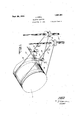
- Figure 1 is a sectionalelevational view thru the body of .a so-call-ed inule spinning machine, showing the location of the indicator and guard which is to be described.
- Figure 2 is a perspective view, showing the cooperation of the guard and indicator device illustrating its method of permitting free movement of the belt when moving in the proper direction and illustrating its engagement when moving in the wrong di rection.
- Figure 3 is a perspective view of the guard, showing the moving belt about to be stopped.
- Figure 4 is an enlarged perspectiv view, showing the device more completely.
- the numeral indicates a platform forming part of a mule spinning machine.
- This platform has bearing brackets 11 mounted thereon in which a shaft 12 is supported. (in the shaft, a relatively long drum 13 is fixed which is provided with a number of concave grooves 14.
- the platform 10 is 2, 1926. Serial No. 85,443.
- a spool spindle 19 has its lower end j'ournall'ed in bearings located in the support 16 and extends upwardly at a slight angle of inclination. Said spindle passes thru the roof frame member 18 and its upper tapering end 20 is adapted to have spools of yarn wound thereon.
- a pulley 21 having a groove 22 therein is seciired.
- the drum is a continuous relat'ively long member having a great number of grooves 14 thereon and one spindle for each groove, the number of spindles used generally in the usual type of spinning machines being over four hundred. These spindles iotate at high speed, 3000 R. P. M-
- Rotation ofthe spindles is accomplished by training belts consisting of knotted cords about the pulleys 21 and the grooved drum 13. These belts comprise lengths 23 and 24: which may be used either crossed when spinning a spool in one direction, the crossed belt being shown in broken lines in Figure 2, or may be used in the opposite direc tion as indicated by the full lines in Figguife 2. I r
- the device is adapted to stop linear movement of thisbelt when the same is inadvertently crossed or twisted as it is: being readjustedto position on the pulleys and drnm dnring the spinning operation.
- the guard consists of a pair of plates 25 attached to the underside of the roof frame member 18 on opposite ends thereof. These plates 25 have arms 26 depending therefrom and at the lower ends of the arms, pins 27 are provided which register in slots 28 formed in a horizontally positioned slide bar 29.
- Tongues 30 extend downwardly from the slide bar 29 at spaced-apart positions, one tongue being provided for each spool spindle. Near the lower ends of these tongues, triangular notches 31 and 32 are formed. .These notches are exactly in line with the side 23 of the belts.
- the guard 29 is adjusted thru its slots 28 on the *h' is raised about the surface pins 27 so that the notches 31 and 32 be adjacent but at a slight distance from the belts 23, allowing the knots 33 to clear the guards, yet near enough to cause said knots to engage the not hes when the belts are twisted about the pulleys, as shown dotted in Figure 2.
- I claim 1 In a spinning machine, means "for preventing wrong rotation of a spool spindle comprising a knotted cord trained about a drum and a pulley, and means between said belt engageable with the knot on said belt for stopping rotation of the spool spindle when said belt is crossed.
- means for preventing wrong rotation of a spool spindle comprising a knotted cord trained about a drum and a pulley, means between said belt engageable with the knot on said belt for stopping rotation of the spool spindle when said belt is crossed comprising a tongue extending downwardly between the belt normally spaced from the length of belt which is engaged by the tongue when said belt is crossed, and means for adjusting the position of said tongue.
- means for preventing wrong rotation of a spool spindle comprising a knotted cord trained about a drum and a pulley
- means between said belt engageable with the knot on said belt for stopping rotation of the spool spindle when said belt is crossed comprising a tongue extending downwardly between the belt normally spaced from the length of belt which is engaged by the tongue when said belt is crossed
- means for adjusting the position of said tongue comprising a horizontal slide bar, means supporting said slide bar, said slide bar having slots at its ends, and pins on said support means registering in said slots.
- means for preventing wrong rotation of a spool spindle comprising a knotted cord trained about a drum and a pulley
- means between said belt engageable with the knot on said belt for stopping rotation of the spool spindle when said belt is crossed comprising a tongue extending downwardly between the belt normally spaced from the length of belt which is engaged by the tongue when said belt is crossed, means for adjusting the position of said tongue comprising a horizontal slide bar, means supporting said slide bar, said slide bar having slots at its ends, pins on said support means registering in said slots, said tongue having triangular notches therein, the belt when crossed being adapted to register in any of said notches causing the knot of said belt to shoulder in one of said notches to prevent movement of said belt.
Landscapes
- Engineering & Computer Science (AREA)
- Mechanical Engineering (AREA)
- Textile Engineering (AREA)
- Spinning Or Twisting Of Yarns (AREA)
Description
S ept. is ,1926.- 1,601,351
J. DIEHL SPINNING MACHINE Filed Feb. 2, 1926 2 Sheets-Sheet 1 INVENTORV JIDieIll mjz 2 Sept; 2 1-", 1926; 1,601,351
- 1 J. DIEHL SPINNING MACHINE Filed Feb. 2, 1926 2 Sheets-Sheet 2 INVENTOR JDiehl ATTORNEY Patented Sept. 28, 1926.
PATENT @FFICE.
JULTUS'ITIEI-Iil, 0F. GAREIEIJD, NEW J s PInNIrie MAorriNii.
Aspire-mat fires February This invention relates to spinning m: chines and the main object is to provide a device which indicates that a bobbin rotating in the wrong direction, and at the same time prevents such rotation. it frequently occurs that as a spool of yarn is half completed or spun upon the spindle of the spinning n'iachin'e, the belt, usually a knotted cord, breaks. The operator of the machine has difiieult in r'eknotting the belt which drives the spool spindles, as the belt is partly concealed behind and beneath panels. Thr'u this concealment, it often happens that the operator trains the belt inv the reverse position with the result that when the spinning machine is again started, the spool spindle will rotate in a reversedirection, causing the yarn which has been spun on the spool to be again unw-oiind. This invention provides a guard which cooperates with the belts rotating the spool spindles in such manner that when the belts are given the wrong, turn about thepu leys of the spool spindles, the knot on the belt will cooperate with the device in stopping movement of that belt and will prevent re verse rotation of the. spool spindle.
The above and other objects will becomeapparent in the description below, in which characters of reference refer to like-named parts in the drawing.
Referring briefly to the drawing, Figure 1 is a sectionalelevational view thru the body of .a so-call-ed inule spinning machine, showing the location of the indicator and guard which is to be described.
Figure 2 is a perspective view, showing the cooperation of the guard and indicator device illustrating its method of permitting free movement of the belt when moving in the proper direction and illustrating its engagement when moving in the wrong di rection.
Figure 3 is a perspective view of the guard, showing the moving belt about to be stopped.
Figure 4 is an enlarged perspectiv view, showing the device more completely.
Referring in detail to the drawing, the numeral indicates a platform forming part of a mule spinning machine. This platform has bearing brackets 11 mounted thereon in which a shaft 12 is supported. (in the shaft, a relatively long drum 13 is fixed which is provided with a number of concave grooves 14. The platform 10 is 2, 1926. Serial No. 85,443.
bounded by a rear wall 15 and a wall structure at the front. At the front of the spinning machine, an inclined support 16' is provided, whit V V of the platform 10. The walls and structure the front of the spinning machine .ppoit a roof frame 17 and 18, the latter of which is used as an anchor to which the guard 29 is attached. A spool spindle 19 has its lower end j'ournall'ed in bearings located in the support 16 and extends upwardly at a slight angle of inclination. Said spindle passes thru the roof frame member 18 and its upper tapering end 20 is adapted to have spools of yarn wound thereon. Intermediate the len th of the spindle between the support 16 or the roof frame member 18, a pulley 21 having a groove 22 therein is seciired. The drum is a continuous relat'ively long member having a great number of grooves 14 thereon and one spindle for each groove, the number of spindles used generally in the usual type of spinning machines being over four hundred. These spindles iotate at high speed, 3000 R. P. M-
Rotation ofthe spindles is accomplished by training belts consisting of knotted cords about the pulleys 21 and the grooved drum 13. These belts comprise lengths 23 and 24: which may be used either crossed when spinning a spool in one direction, the crossed belt being shown in broken lines in Figure 2, or may be used in the opposite direc tion as indicated by the full lines in Figguife 2. I r
The device is adapted to stop linear movement of thisbelt when the same is inadvertently crossed or twisted as it is: being readjustedto position on the pulleys and drnm dnring the spinning operation. The guard consists of a pair of plates 25 attached to the underside of the roof frame member 18 on opposite ends thereof. These plates 25 have arms 26 depending therefrom and at the lower ends of the arms, pins 27 are provided which register in slots 28 formed in a horizontally positioned slide bar 29. Tongues 30 extend downwardly from the slide bar 29 at spaced-apart positions, one tongue being provided for each spool spindle. Near the lower ends of these tongues, triangular notches 31 and 32 are formed. .These notches are exactly in line with the side 23 of the belts.
Preparatory to operating the machine, the guard 29 is adjusted thru its slots 28 on the *h' is raised about the surface pins 27 so that the notches 31 and 32 be adjacent but at a slight distance from the belts 23, allowing the knots 33 to clear the guards, yet near enough to cause said knots to engage the not hes when the belts are twisted about the pulleys, as shown dotted in Figure 2.
In operation, a source of power, about the drum and the rotating in one direction, the belts are in the position indicated by the full lines in Figures 2 and 4:. Then in this position, the threads of the spool are rotated on the spool in one direction. Should the belt break, a new knotted belt must be provided. These belts are partly concealed in a housing so that the operator of the machine finds it necessary to manipulate a hook or wire to again place the belts upon the pulley 21, after the spindles 20 have been pulled upwardly. It frequently occurs that the operator, thru not being. able to see the adjustment, twists the belts as indicated by the broken lines in Figure 2. It this'occurs when a spool is only partly wound, said spool would again be unwound, were the power of the machine turned on. Such inadvertent twisting of the belt would be indicated and unravelling of the spool would be prevented by the device illustrated in Figure 3. When the belt is inadvertently crossed, the length 23 thereof will be guided into the notch 31 and if the power of the machine is then turned on, the belt will move until the knot 33 wedges itself in the notch 31, preventing the drum 13 is rotated thru with the belts trained pulleys 21. When further rotation of this belt and thus preventing the partly completed spool from being unwound. When the operator observes this, he shuts oil the power and reverses the belt.
I claim 1. In a spinning machine, means "for preventing wrong rotation of a spool spindle comprising a knotted cord trained about a drum and a pulley, and means between said belt engageable with the knot on said belt for stopping rotation of the spool spindle when said belt is crossed.
2. In a spinning machine, means for preventing wrong rotation of a spool spindle comprising a knotted cord trained about a drum and a pulley, means between said belt engageable with the knot on said belt for stopping rotation of the spool spindle when said belt is crossed comprising a tongue extending downwardly between the belt normally spaced from the length of belt which is engaged by the tongue when said belt is crossed, and means for adjusting the position of said tongue.
3. In a spinning machine, means for preventing wrong rotation of a spool spindle comprising a knotted cord trained about a drum and a pulley, means between said belt engageable with the knot on said belt for stopping rotation of the spool spindle when said belt is crossed comprising a tongue extending downwardly between the belt normally spaced from the length of belt which is engaged by the tongue when said belt is crossed, means for adjusting the position of said tongue comprising a horizontal slide bar, means supporting said slide bar, said slide bar having slots at its ends, and pins on said support means registering in said slots.
4. In a spinning machine, means for preventing wrong rotation of a spool spindle comprising a knotted cord trained about a drum and a pulley, means between said belt engageable with the knot on said belt for stopping rotation of the spool spindle when said belt is crossed comprising a tongue extending downwardly between the belt normally spaced from the length of belt which is engaged by the tongue when said belt is crossed, means for adjusting the position of said tongue comprising a horizontal slide bar, means supporting said slide bar, said slide bar having slots at its ends, pins on said support means registering in said slots, said tongue having triangular notches therein, the belt when crossed being adapted to register in any of said notches causing the knot of said belt to shoulder in one of said notches to prevent movement of said belt.
In testimony whereof I afiix my signature.
JULIUS DIEHL.
Priority Applications (1)
| Application Number | Priority Date | Filing Date | Title |
|---|---|---|---|
| US85443A US1601351A (en) | 1926-02-02 | 1926-02-02 | Spinning machine |
Applications Claiming Priority (1)
| Application Number | Priority Date | Filing Date | Title |
|---|---|---|---|
| US85443A US1601351A (en) | 1926-02-02 | 1926-02-02 | Spinning machine |
Publications (1)
| Publication Number | Publication Date |
|---|---|
| US1601351A true US1601351A (en) | 1926-09-28 |
Family
ID=22191618
Family Applications (1)
| Application Number | Title | Priority Date | Filing Date |
|---|---|---|---|
| US85443A Expired - Lifetime US1601351A (en) | 1926-02-02 | 1926-02-02 | Spinning machine |
Country Status (1)
| Country | Link |
|---|---|
| US (1) | US1601351A (en) |
-
1926
- 1926-02-02 US US85443A patent/US1601351A/en not_active Expired - Lifetime
Similar Documents
| Publication | Publication Date | Title |
|---|---|---|
| US1601351A (en) | Spinning machine | |
| US2133507A (en) | Warp tensioning control | |
| US3305896A (en) | Creel stop motion | |
| US305502A (en) | Warping-machine | |
| US1170212A (en) | Winding-machine. | |
| US1721628A (en) | Double inspection jack spooler | |
| US2301712A (en) | Yarn winding machine | |
| US361588A (en) | hebbelynck | |
| US732439A (en) | Unwrapping mechanism for yarn-chains. | |
| US731883A (en) | Twisting-head for thread-dressing machines. | |
| US1961694A (en) | Spindle mounting for creels | |
| US865685A (en) | Spinning, twisting, and winding machine. | |
| US1489478A (en) | Twisting frame for threads or filaments | |
| US2158607A (en) | Thread drawing off device on double twist twisting machines | |
| US330035A (en) | Island | |
| US2065363A (en) | Winding machine | |
| US283599A (en) | -grant | |
| US1783897A (en) | Yarn stop motion for twisting machines | |
| US909426A (en) | Flier. | |
| US1252180A (en) | Cleaner for spinning-machines. | |
| US1903588A (en) | Regulator for winding on installations | |
| US2093628A (en) | Winding machine | |
| US733608A (en) | Needle-frame for spinning-machines. | |
| US340631A (en) | Tension device for silk-spinning machines | |
| US905231A (en) | Flier spinning-frame. |