US1574493A - Sheet-metal door - Google Patents
Sheet-metal door Download PDFInfo
- Publication number
- US1574493A US1574493A US47426A US4742625A US1574493A US 1574493 A US1574493 A US 1574493A US 47426 A US47426 A US 47426A US 4742625 A US4742625 A US 4742625A US 1574493 A US1574493 A US 1574493A
- Authority
- US
- United States
- Prior art keywords
- door
- stile
- stiles
- edges
- nosing
- Prior art date
- Legal status (The legal status is an assumption and is not a legal conclusion. Google has not performed a legal analysis and makes no representation as to the accuracy of the status listed.)
- Expired - Lifetime
Links
Images

Classifications
-
- E—FIXED CONSTRUCTIONS
- E06—DOORS, WINDOWS, SHUTTERS, OR ROLLER BLINDS IN GENERAL; LADDERS
- E06B—FIXED OR MOVABLE CLOSURES FOR OPENINGS IN BUILDINGS, VEHICLES, FENCES OR LIKE ENCLOSURES IN GENERAL, e.g. DOORS, WINDOWS, BLINDS, GATES
- E06B3/00—Window sashes, door leaves, or like elements for closing wall or like openings; Layout of fixed or moving closures, e.g. windows in wall or like openings; Features of rigidly-mounted outer frames relating to the mounting of wing frames
- E06B3/96—Corner joints or edge joints for windows, doors, or the like frames or wings
- E06B3/988—Corner joints or edge joints for windows, doors, or the like frames or wings specially adapted for sheet metal frame members with an open U-shaped cross-section
-
- E—FIXED CONSTRUCTIONS
- E06—DOORS, WINDOWS, SHUTTERS, OR ROLLER BLINDS IN GENERAL; LADDERS
- E06B—FIXED OR MOVABLE CLOSURES FOR OPENINGS IN BUILDINGS, VEHICLES, FENCES OR LIKE ENCLOSURES IN GENERAL, e.g. DOORS, WINDOWS, BLINDS, GATES
- E06B3/00—Window sashes, door leaves, or like elements for closing wall or like openings; Layout of fixed or moving closures, e.g. windows in wall or like openings; Features of rigidly-mounted outer frames relating to the mounting of wing frames
- E06B3/70—Door leaves
- E06B3/72—Door leaves consisting of frame and panels, e.g. of raised panel type
- E06B3/725—Door leaves consisting of frame and panels, e.g. of raised panel type with separate hollow frames, e.g. foam-filled
- E06B3/726—Door leaves consisting of frame and panels, e.g. of raised panel type with separate hollow frames, e.g. foam-filled of metal
- E06B3/728—Door leaves consisting of frame and panels, e.g. of raised panel type with separate hollow frames, e.g. foam-filled of metal of sheet metal
-
- E—FIXED CONSTRUCTIONS
- E06—DOORS, WINDOWS, SHUTTERS, OR ROLLER BLINDS IN GENERAL; LADDERS
- E06B—FIXED OR MOVABLE CLOSURES FOR OPENINGS IN BUILDINGS, VEHICLES, FENCES OR LIKE ENCLOSURES IN GENERAL, e.g. DOORS, WINDOWS, BLINDS, GATES
- E06B3/00—Window sashes, door leaves, or like elements for closing wall or like openings; Layout of fixed or moving closures, e.g. windows in wall or like openings; Features of rigidly-mounted outer frames relating to the mounting of wing frames
- E06B3/70—Door leaves
- E06B3/88—Edge-protecting devices for door leaves
-
- Y—GENERAL TAGGING OF NEW TECHNOLOGICAL DEVELOPMENTS; GENERAL TAGGING OF CROSS-SECTIONAL TECHNOLOGIES SPANNING OVER SEVERAL SECTIONS OF THE IPC; TECHNICAL SUBJECTS COVERED BY FORMER USPC CROSS-REFERENCE ART COLLECTIONS [XRACs] AND DIGESTS
- Y10—TECHNICAL SUBJECTS COVERED BY FORMER USPC
- Y10T—TECHNICAL SUBJECTS COVERED BY FORMER US CLASSIFICATION
- Y10T70/00—Locks
- Y10T70/80—Parts, attachments, accessories and adjuncts
- Y10T70/8432—For key-operated mechanism
- Y10T70/8459—Housings
- Y10T70/8541—Mounting arrangements
Definitions
- My invention relates to doors. and similar structures which are formed of sheet metal, the various portions whereof are secured to each other as by interlocking flanges, to facilitate ready assembling of the structure; and my invention is particularly directed to improvements whereby the elements of the door, with the exception of its exterior edges, may be assembled in their proper relations, after which suitable edge ele ments of optionally selected designs may be interlocked therewith and secured in position to complete the door.
- doors of the sheet metal or fireproof character are used, there is frequently delay in the selection of the hardware which. is to be mount ed on the doors, and also, sometimes, of the style of the nosing or front edge element of the door, in consequence of which the completion of the door is frequently held up. This retards the work in the factory; for before the stiles are assembled with the top and bottom and panelelements of the door, it is a practical necessity that particular hardware should have been selected and appropriate seats prepared for it in the stiles.
- the objects of my invention are to produce a door, the bottom, stiles and panels of which can be assembled in their proper relations in advance of the selection and manufacture of the particular style of edge elements or of the hardware to be mounted on the stiles; to form. separate, supplemental edge elements adapted to be interlocked with the stiles to complete them; and other edge elements adapted to be introduced to close the top and bottom of the door; to provide the edge elements for the stile with suitable means for the attachment of the appropriate hardware; to complete the door by the insertion of the completed edge elements and by permanently securing them in position; and to accomplish all this in a simple, stron and practical manner adapt ed to meet 1; e requirements of actual use.
- I use certain novel features which I will point out and explain in this specification.
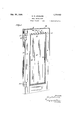
- Fig. 1 is a perspective view of the door embodying my improvements
- Fig. 2 is a similar View of the door showing the edge elements detached and set 011' from it
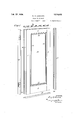
- Fig. 3 is a perspective view of the back stile and its edge element partly slid into place, medial portions of the stile and edging being omitted, to shorten the view, and one hinge being shown as attached to the edging
- Fig. 4 is a perspective view of a section of the nosing or front stile edging, showing a lock mounted therein
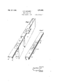
- Fig. 5 is a cross sectional view taken as on the line 5-5 of Fig. 1, looking down;
- Fig. 5 is a cross sectional view taken as on the line 5-5 of Fig. 1, looking down; Fig.
- FIG. 6 is a vertical sectional view of a corner of the door taken as on the line 6-6 of Fig. 1;
- Fig. 7 is a cross sectional view taken as on the line 7-7 of Fig. 6, looking down,
- Fig. 8 is a cross sectional view showing a modified form of top closure;
- Figs. 9, 10 and 11 are cross sectional views of modified forms of front stile edgings or nosings.
- the bodies of the front stile 1, the back stile 2, the top rail 3 and the bottom rail 4 are made of channel pieces, separated at their outer edges, and adapted to be interlocked with each other, for instance, by the use of sockets 5, 5 in the stiles, into which lugs 6, 6 on the ends of the rails may be hooked; and the inner edges of the stiles, top and bottom, are, preferably, provided with channels, formed by bending the metal of the body inward and outward again, as illustrated at 7 8 and 9 on the drawings, the formation of the bottom rail in this respect being similar to that of the top rail.
- the panel 10 may be placed in suitable spacing strips as 11, 11, within m0ldings12, 12, and this assembly mounted within the channels in the stiles and the rails, and those elements interlocked so as to hold the panel and molding in proper relation, and the door, thus far assembled, may be set aside until it is convenient to apply the edge elements.
- the stiles and rails may, also, if de-v sired, be spot welded at their points of junction to stiffen the structure and permanently unite those parts.
- the outer edges of the bodies of the stiles are, preferably,-recurved or turned inward as shown at 15 and 16; and the free edges of the front nosing 17 and closing strip 19 open edges of the stiles will be bridged and adequately supported in their proper posi-
- the nosing 17 is, preferably, reinforced lliy a plate 22, indicated in broken lines in ig. 4, through which a lock 23 may be inserted, and to which the lock may be secured by suitable fastenings such as bolts 24.
- the plate 22 may be permanently fastened to the nosing .as by spot welding. It will be seen that the lock can be thus mounted on the nosing before the nosing is slid into position in the stile.
- a back stop 19 also, preferably, is reinforced by a plate or plates 26 forming appropriate anchorages for hinges 27
- These plates may be secured in position by bolts 28 threaded into anchors 25 adapted to lie across the inturned edges 16, 16 of the backstop 19, so that the plates 26 may be clamped in position by clamping the plates and their anchors firmly against opposite shoulders of the inturned flan es of the back stop 19 by screwing in the bolts 28.
- the plates 26 may be prepared of the appropriate size, and properlytapped to receive the particular style of hinge which may be selected for the door, and to receive which the back stop has been socketed; and the plates may then be slid into their appropriate positions behind the sockets and firmly anchored there.
- the screw 28 can be further tightened, if desired, to stiffen the joint between the flanges 16 and 21.
- the hinges 27 may be attached to the plates 26, either before or after the back stop has been slid into place, by suitable means such as bolts 29.
- the top of the door may be closed in by the insertion of a channel element 30, which will be supported by the ends of the webs 31 and 32 in the front and back stiles.
- the channel closure may be spot welded in position if desired.
- the bottom of the door may be closed with a similar closure 33, also secured by spot welding or in any other suitable manner.
- a flush closure may be made by turning the channel closures over so that their flanges extend inward instead of outward; or an additional and reverse closure element such as 34, shown in Fig. 8, may be used in conjunction with the closure elements abovesuggested.
- Figs. 9 and 10 illustrate modified forms ravages nosing may thus, readily, be applied to a stock body, so that the nosing only and not the whole stile will have to be specially made.
Description
. E. R. LEONARD SHEET METAL DOOR Feb. 23,1926. 1,574,493
Filed August 1, 1925 l 4 SheetsSheet 2 A 30 f/Z' Z L\fl Z0 21 fl A I I INVENTOR.
A TTORNEY.
1,574,493 E. R. LEONARD SHEET METAL DOOR Feb. 23 1926.
Filed August 1, 1925 4 Sheets-Sheet 5 IN VEN TOR.
I A TTORNEYJ E. R. LEONARD SHEET METAL DOOR.
Filed August 1', 1925 4 Sheets-Sheet 4 yvy ll o ilil I N V EN TOR.
ATTORNEX Feb; 23 1926.
Patented Feb. 23, 192.
ELOF R. LEONARD, 0F MOUNTAIN LAKES, NEW JERSEY.
SHEET-METAL DOOR.
Application filed August 1, 1925. Serial No. 47,426.
To all whom it may. concern:
Be it known that I, ELOF R. LEONARD, a citizen of the United States, residing at Mountain Lakes, Morris County, New Jersey, have invented certain new and useful Improvements in Sheet-Metal Doors, of which the following is a specification.
My invention relates to doors. and similar structures which are formed of sheet metal, the various portions whereof are secured to each other as by interlocking flanges, to facilitate ready assembling of the structure; and my invention is particularly directed to improvements whereby the elements of the door, with the exception of its exterior edges, may be assembled in their proper relations, after which suitable edge ele ments of optionally selected designs may be interlocked therewith and secured in position to complete the door. Where doors of the sheet metal or fireproof character are used, there is frequently delay in the selection of the hardware which. is to be mount ed on the doors, and also, sometimes, of the style of the nosing or front edge element of the door, in consequence of which the completion of the door is frequently held up. This retards the work in the factory; for before the stiles are assembled with the top and bottom and panelelements of the door, it is a practical necessity that particular hardware should have been selected and appropriate seats prepared for it in the stiles.
The objects of my invention are to produce a door, the bottom, stiles and panels of which can be assembled in their proper relations in advance of the selection and manufacture of the particular style of edge elements or of the hardware to be mounted on the stiles; to form. separate, supplemental edge elements adapted to be interlocked with the stiles to complete them; and other edge elements adapted to be introduced to close the top and bottom of the door; to provide the edge elements for the stile with suitable means for the attachment of the appropriate hardware; to complete the door by the insertion of the completed edge elements and by permanently securing them in position; and to accomplish all this in a simple, stron and practical manner adapt ed to meet 1; e requirements of actual use. In accomplishing these results I use certain novel features which I will point out and explain in this specification.
In the drawings, Fig. 1 is a perspective view of the door embodying my improvements; Fig. 2 is a similar View of the door showing the edge elements detached and set 011' from it; Fig. 3 is a perspective view of the back stile and its edge element partly slid into place, medial portions of the stile and edging being omitted, to shorten the view, and one hinge being shown as attached to the edging; Fig. 4 is a perspective view of a section of the nosing or front stile edging, showing a lock mounted therein; Fig. 5 is a cross sectional view taken as on the line 5-5 of Fig. 1, looking down; Fig. 6 is a vertical sectional view of a corner of the door taken as on the line 6-6 of Fig. 1; Fig. 7 is a cross sectional view taken as on the line 7-7 of Fig. 6, looking down, Fig. 8 is a cross sectional view showing a modified form of top closure; Figs. 9, 10 and 11 are cross sectional views of modified forms of front stile edgings or nosings.
In all the figures similar parts are designated by corresponding reference numerals. The bodies of the front stile 1, the back stile 2, the top rail 3 and the bottom rail 4 are made of channel pieces, separated at their outer edges, and adapted to be interlocked with each other, for instance, by the use of sockets 5, 5 in the stiles, into which lugs 6, 6 on the ends of the rails may be hooked; and the inner edges of the stiles, top and bottom, are, preferably, provided with channels, formed by bending the metal of the body inward and outward again, as illustrated at 7 8 and 9 on the drawings, the formation of the bottom rail in this respect being similar to that of the top rail.
In assembling the door, therefore, the panel 10 may be placed in suitable spacing strips as 11, 11, within m0ldings12, 12, and this assembly mounted within the channels in the stiles and the rails, and those elements interlocked so as to hold the panel and molding in proper relation, and the door, thus far assembled, may be set aside until it is convenient to apply the edge elements. The stiles and rails may, also, if de-v sired, be spot welded at their points of junction to stiffen the structure and permanently unite those parts. I The outer edges of the bodies of the stiles are, preferably,-recurved or turned inward as shown at 15 and 16; and the free edges of the front nosing 17 and closing strip 19 open edges of the stiles will be bridged and adequately supported in their proper posi- The nosing 17 is, preferably, reinforced lliy a plate 22, indicated in broken lines in ig. 4, through which a lock 23 may be inserted, and to which the lock may be secured by suitable fastenings such as bolts 24. The plate 22 may be permanently fastened to the nosing .as by spot welding. It will be seen that the lock can be thus mounted on the nosing before the nosing is slid into position in the stile.
A back stop 19 also, preferably, is reinforced by a plate or plates 26 forming appropriate anchorages for hinges 27 These plates may be secured in position by bolts 28 threaded into anchors 25 adapted to lie across the inturned edges 16, 16 of the backstop 19, so that the plates 26 may be clamped in position by clamping the plates and their anchors firmly against opposite shoulders of the inturned flan es of the back stop 19 by screwing in the bolts 28. It will be seen, therefore, that the plates 26 may be prepared of the appropriate size, and properlytapped to receive the particular style of hinge which may be selected for the door, and to receive which the back stop has been socketed; and the plates may then be slid into their appropriate positions behind the sockets and firmly anchored there. After the back stop has been slid into its stile, the screw 28 can be further tightened, if desired, to stiffen the joint between the flanges 16 and 21. The hinges 27 may be attached to the plates 26, either before or after the back stop has been slid into place, by suitable means such as bolts 29.
When the nosing and back stop have been interlocked with their stiles in proper position, the top of the door may be closed in by the insertion of a channel element 30, which will be supported by the ends of the webs 31 and 32 in the front and back stiles. The channel closure may be spot welded in position if desired. The bottom of the door may be closed with a similar closure 33, also secured by spot welding or in any other suitable manner.
If desired, a flush closuremay be made by turning the channel closures over so that their flanges extend inward instead of outward; or an additional and reverse closure element such as 34, shown in Fig. 8, may be used in conjunction with the closure elements abovesuggested.
Figs. 9 and 10 illustrate modified forms ravages nosing may thus, readily, be applied to a stock body, so that the nosing only and not the whole stile will have to be specially made.
By means of my improvements I am enabled to produce a door the body of which may be made and assembled in advance of the selection of the hardware and the particular style of nosing and back stop that may be desired; and those parts may afterwards be made independently and readily inserted into the assembled body, when desired, to
complete the door, its top and bottom bein suitably closed as by means above suggeste This is a highly desirable thing in the practical art.
It will be understood that the form of door which I have illustrated and described is to be regarded as a typical and not as an exclusive embodiment of my invention. For details of construction may be modified by the use of mechanical equivalents and the like without departing from the spirit of my invention or the scope of my claims.
Having thus described my invention, what I claim and desire to secure by Letters Patent of the United States is 1. In a sheet metal door, the combination, with rails, and with stiles each grooved on their inner edges and open on their outer edges and provided with means for interlocking them with the rails and with means for slidably engaging an edging element, and paneling, of edging elements each provided with means for slidably engaging the engaging elements of a stile to close and complete the stile.
2. In a sheet metal door, the combination, with a unitary assembly embodying a. front stile having an open, outer edge, of a readily attachable and interlocking nosing provided with lock carrying means. 7
3. In a sheet metal door, the combination with a unitary assembly embodyin 'a back stile havin ily attacha 1e and interlocking back stop provided with hinge carryin means.
4:. In asheet metal door, t e combination with a unitary assembly embodying front and back stiles having open, outer edges, of
readily attachable nosing provided with lock carrying means and adapted to interlock with the and close the open edge 'of the front stile, and a readily attachable back stop provided with hinge carrying means adapted to interlock with and close the open edge of the back stile.
5. In a sheet metal door, the combination an open, outer edge, 0 a read-5;:
Lenses with a unitary structure embodying a hack stile with free inturned outer edges, of a back stop provided with inturned shouldersand free, outturned edges adapted to slidably interlock with the inturned edges of the stile, and hinge receiving means, disposed within the back stops, and means for clamping the same against said shoulders.
6. In a sheet metal door, the combination with a unitary structure embodying a hack stile with free inturned outerv edges, of a hack stop provided with inturned shoulders and free, outturned edges ada ted to slidably interlock with the inturne edges of the stile, and hinge receiving means, disposed within the back stop, and means, consisting of a bolt and an anchor disposed beyond the outturned edges, for clamping the same against said shoulders. 1
ELOF R. LEONARD.
Priority Applications (1)
| Application Number | Priority Date | Filing Date | Title |
|---|---|---|---|
| US47426A US1574493A (en) | 1925-08-01 | 1925-08-01 | Sheet-metal door |
Applications Claiming Priority (1)
| Application Number | Priority Date | Filing Date | Title |
|---|---|---|---|
| US47426A US1574493A (en) | 1925-08-01 | 1925-08-01 | Sheet-metal door |
Publications (1)
| Publication Number | Publication Date |
|---|---|
| US1574493A true US1574493A (en) | 1926-02-23 |
Family
ID=21948899
Family Applications (1)
| Application Number | Title | Priority Date | Filing Date |
|---|---|---|---|
| US47426A Expired - Lifetime US1574493A (en) | 1925-08-01 | 1925-08-01 | Sheet-metal door |
Country Status (1)
| Country | Link |
|---|---|
| US (1) | US1574493A (en) |
Cited By (20)
| Publication number | Priority date | Publication date | Assignee | Title |
|---|---|---|---|---|
| US2567357A (en) * | 1948-01-14 | 1951-09-11 | Diebold Inc | Hollow metal door construction |
| US2677443A (en) * | 1948-01-09 | 1954-05-04 | Virginia Metal Products Inc | Door construction |
| US2692664A (en) * | 1948-03-15 | 1954-10-26 | William A Ternes | Door construction and method of making the same |
| US2889899A (en) * | 1953-06-30 | 1959-06-09 | Burch Company | Metal door construction |
| US2951566A (en) * | 1959-04-08 | 1960-09-06 | Armenti Natale | Storm door side rail construction |
| US3026704A (en) * | 1959-08-14 | 1962-03-27 | American Hardware Corp | Lock mounting means |
| US3084611A (en) * | 1959-12-02 | 1963-04-09 | Walcon Corp | Operating louver construction |
| US3458955A (en) * | 1967-05-01 | 1969-08-05 | Ppg Industries Inc | Door construction |
| US4087942A (en) * | 1977-04-04 | 1978-05-09 | Precision Industries, Inc. | Steel door construction |
| FR2415189A1 (en) * | 1978-01-18 | 1979-08-17 | Le Bihan Et Le Mouel Sa | Hollow door of sheet metal sections - comprising ribbed or plane facia sheets joining edge members of U=section with single central web step |
| US4832388A (en) * | 1986-03-14 | 1989-05-23 | Lozano Anthony R | Door assembly and components thereof applicable to increase resistance to forced entry |
| US4854622A (en) * | 1985-02-27 | 1989-08-08 | Lozano Anthony R | Door assembly incorporating means to increase resistance to forced entry |
| US4897975A (en) * | 1987-10-23 | 1990-02-06 | Odl, Incorporated | Integral door light with glazing stop |
| US4920718A (en) * | 1988-03-17 | 1990-05-01 | Odl, Incorporated | Integral door light and related door construction |
| EP0432339A1 (en) * | 1989-12-15 | 1991-06-19 | Swedoor Ab | A sheet metal door frame and a method for installing the same in a doorway |
| US6622449B2 (en) | 2002-01-29 | 2003-09-23 | Mdf, Inc. | Door panel and method of forming same |
| US20040031204A1 (en) * | 2002-08-14 | 2004-02-19 | Ronald Thompson | Door mounting assembly and method |
| US20060101644A1 (en) * | 2002-09-12 | 2006-05-18 | Yong Toong C | Method and apparatus for assembling a 2-piece skin door |
| USD789553S1 (en) * | 2014-07-30 | 2017-06-13 | Masonite Corporation | Door |
| USD790728S1 (en) * | 2014-07-30 | 2017-06-27 | Masonite Corporation | Door |
-
1925
- 1925-08-01 US US47426A patent/US1574493A/en not_active Expired - Lifetime
Cited By (30)
| Publication number | Priority date | Publication date | Assignee | Title |
|---|---|---|---|---|
| US2677443A (en) * | 1948-01-09 | 1954-05-04 | Virginia Metal Products Inc | Door construction |
| US2567357A (en) * | 1948-01-14 | 1951-09-11 | Diebold Inc | Hollow metal door construction |
| US2692664A (en) * | 1948-03-15 | 1954-10-26 | William A Ternes | Door construction and method of making the same |
| US2889899A (en) * | 1953-06-30 | 1959-06-09 | Burch Company | Metal door construction |
| US2951566A (en) * | 1959-04-08 | 1960-09-06 | Armenti Natale | Storm door side rail construction |
| US3026704A (en) * | 1959-08-14 | 1962-03-27 | American Hardware Corp | Lock mounting means |
| US3084611A (en) * | 1959-12-02 | 1963-04-09 | Walcon Corp | Operating louver construction |
| US3458955A (en) * | 1967-05-01 | 1969-08-05 | Ppg Industries Inc | Door construction |
| US4087942A (en) * | 1977-04-04 | 1978-05-09 | Precision Industries, Inc. | Steel door construction |
| FR2415189A1 (en) * | 1978-01-18 | 1979-08-17 | Le Bihan Et Le Mouel Sa | Hollow door of sheet metal sections - comprising ribbed or plane facia sheets joining edge members of U=section with single central web step |
| US4854622A (en) * | 1985-02-27 | 1989-08-08 | Lozano Anthony R | Door assembly incorporating means to increase resistance to forced entry |
| US4832388A (en) * | 1986-03-14 | 1989-05-23 | Lozano Anthony R | Door assembly and components thereof applicable to increase resistance to forced entry |
| US4897975A (en) * | 1987-10-23 | 1990-02-06 | Odl, Incorporated | Integral door light with glazing stop |
| US4920718A (en) * | 1988-03-17 | 1990-05-01 | Odl, Incorporated | Integral door light and related door construction |
| EP0432339A1 (en) * | 1989-12-15 | 1991-06-19 | Swedoor Ab | A sheet metal door frame and a method for installing the same in a doorway |
| WO1991009168A1 (en) * | 1989-12-15 | 1991-06-27 | Swedoor Ab | A sheet metal door frame and a method for installing the same in a doorway |
| US5295327A (en) * | 1989-12-15 | 1994-03-22 | Swedoor Ab | Sheet metal door frame and a method for installing the same in a doorway |
| US6622449B2 (en) | 2002-01-29 | 2003-09-23 | Mdf, Inc. | Door panel and method of forming same |
| US20040031204A1 (en) * | 2002-08-14 | 2004-02-19 | Ronald Thompson | Door mounting assembly and method |
| US20060101644A1 (en) * | 2002-09-12 | 2006-05-18 | Yong Toong C | Method and apparatus for assembling a 2-piece skin door |
| US7478469B2 (en) * | 2002-09-12 | 2009-01-20 | Malaysia Woodworking (Pte) Ltd | Method and apparatus for assembling a 2-piece skin door |
| USD789553S1 (en) * | 2014-07-30 | 2017-06-13 | Masonite Corporation | Door |
| USD790728S1 (en) * | 2014-07-30 | 2017-06-27 | Masonite Corporation | Door |
| USD827860S1 (en) * | 2014-07-30 | 2018-09-04 | Masonite Corporation | Door |
| USD844175S1 (en) * | 2014-07-30 | 2019-03-26 | Masonite Corporation | Door facing |
| USD888991S1 (en) * | 2014-07-30 | 2020-06-30 | Masonite Corporation | Door |
| USD888990S1 (en) * | 2014-07-30 | 2020-06-30 | Masonite Corporation | Door |
| USD938065S1 (en) * | 2014-07-30 | 2021-12-07 | Masonite Corporation | Door |
| USD946172S1 (en) * | 2014-07-30 | 2022-03-15 | Masonite Corporation | Door |
| USD1001315S1 (en) * | 2014-07-30 | 2023-10-10 | Masonite Corporation | Door |
Similar Documents
| Publication | Publication Date | Title |
|---|---|---|
| US1574493A (en) | Sheet-metal door | |
| US3271919A (en) | Door edge protector | |
| US3834101A (en) | Insulated door construction | |
| US2910154A (en) | Door frame assembly | |
| US3121264A (en) | Door | |
| EP2025822A2 (en) | Frame construction | |
| US3703061A (en) | Overhead door construction | |
| US2874420A (en) | Metal door frame | |
| US1701679A (en) | Building construction | |
| US1420473A (en) | Partition for buildings | |
| US3104428A (en) | Pilaster structures and hinge bracket assemblies | |
| US1104868A (en) | Metal door. | |
| US1271210A (en) | Sheet-metal structure. | |
| US1328918A (en) | Metal door construction | |
| US1950401A (en) | Metallic window sash and casing construction | |
| FR2497866A1 (en) | Steel-clad security door - carries iron corner pieces along edges which fit into similarly reinforced frame | |
| US1825878A (en) | Door construction | |
| US2284480A (en) | Furniture | |
| US1039292A (en) | Sheet-metal door and the like. | |
| US2710080A (en) | Door construction | |
| US1676599A (en) | Body construction | |
| US1737403A (en) | Door framing | |
| US1045580A (en) | Metallic sash. | |
| US2972165A (en) | Trim strip | |
| US2021375A (en) | Door construction |