US1574490A - Box-nailling machine - Google Patents
Box-nailling machine Download PDFInfo
- Publication number
- US1574490A US1574490A US753873A US75387324A US1574490A US 1574490 A US1574490 A US 1574490A US 753873 A US753873 A US 753873A US 75387324 A US75387324 A US 75387324A US 1574490 A US1574490 A US 1574490A
- Authority
- US
- United States
- Prior art keywords
- nailing
- nailers
- nail
- head
- cross
- Prior art date
- Legal status (The legal status is an assumption and is not a legal conclusion. Google has not performed a legal analysis and makes no representation as to the accuracy of the status listed.)
- Expired - Lifetime
Links
- 230000007246 mechanism Effects 0.000 description 52
- 238000007514 turning Methods 0.000 description 10
- 230000007935 neutral effect Effects 0.000 description 5
- 230000000284 resting effect Effects 0.000 description 5
- 239000000463 material Substances 0.000 description 4
- 239000000725 suspension Substances 0.000 description 4
- 230000003472 neutralizing effect Effects 0.000 description 3
- 238000013459 approach Methods 0.000 description 2
- 210000000988 bone and bone Anatomy 0.000 description 2
- 230000000994 depressogenic effect Effects 0.000 description 2
- 235000013399 edible fruits Nutrition 0.000 description 2
- 101100514821 Caenorhabditis elegans dsc-4 gene Proteins 0.000 description 1
- RUPBZQFQVRMKDG-UHFFFAOYSA-M Didecyldimethylammonium chloride Chemical compound [Cl-].CCCCCCCCCC[N+](C)(C)CCCCCCCCCC RUPBZQFQVRMKDG-UHFFFAOYSA-M 0.000 description 1
- 239000012267 brine Substances 0.000 description 1
- 230000005484 gravity Effects 0.000 description 1
- 239000000314 lubricant Substances 0.000 description 1
- 230000001050 lubricating effect Effects 0.000 description 1
- 230000004048 modification Effects 0.000 description 1
- 238000012986 modification Methods 0.000 description 1
- HPALAKNZSZLMCH-UHFFFAOYSA-M sodium;chloride;hydrate Chemical compound O.[Na+].[Cl-] HPALAKNZSZLMCH-UHFFFAOYSA-M 0.000 description 1
- 235000013311 vegetables Nutrition 0.000 description 1
Images


Classifications
-
- B—PERFORMING OPERATIONS; TRANSPORTING
- B27—WORKING OR PRESERVING WOOD OR SIMILAR MATERIAL; NAILING OR STAPLING MACHINES IN GENERAL
- B27F—DOVETAILED WORK; TENONS; SLOTTING MACHINES FOR WOOD OR SIMILAR MATERIAL; NAILING OR STAPLING MACHINES
- B27F7/00—Nailing or stapling; Nailed or stapled work
- B27F7/02—Nailing machines
- B27F7/05—Driving means
- B27F7/11—Driving means operated by electric power
-
- B—PERFORMING OPERATIONS; TRANSPORTING
- B27—WORKING OR PRESERVING WOOD OR SIMILAR MATERIAL; NAILING OR STAPLING MACHINES IN GENERAL
- B27F—DOVETAILED WORK; TENONS; SLOTTING MACHINES FOR WOOD OR SIMILAR MATERIAL; NAILING OR STAPLING MACHINES
- B27F7/00—Nailing or stapling; Nailed or stapled work
- B27F7/02—Nailing machines
Definitions
- This invention relates to devices for assembling and nailing bones.
- One of the objects of this invention is to provide a device or machine in which the different nailing mechanism are operated by individual electric motors.
- Another object is to provide a plurality of individually operated nailing units suspended at their upper ends in a common main frame ⁇ so that the lower ends of the different nailing units can be moved in any direction away from their center line of gravity.
- Another object is to provide a plurality of individually operated nailing units suspended within the main frame, embodying 'controlling mechanism by which the lower free ends can be controlled in certain positions in relation to the work to be performed.
- Another object is to provide a threaded stem or spindle on an electric motor by which a nailing mechanism can be forced downwardly when operatively engaged with the threaded spindle of such electric motor.
- Another object is to provideV a plurality of nailers within a nailing unit by which several nails may be driven by one operation of such unit.
- Another object is to provide mechanism by which several nailers in a unit can be controlled in certain spaced relation to one another, so that nails may be driven by such a unit with various spaces between the nails.
- Another' object is to provide mechanism by which nails can be automatically placed with varying spacing, by one and the ⁇ same nailing unit during the operation with a nailing machine.
- Another object is to provide a nailhfeeding mechanism by which various nails may be used in the dierent nailers of a nailing unit during a continuous operation of a nailing machine.
- Another object is to provide several nailers in one unit embodying means by which any of the nailers in the unit may be moved to and held in neutral, inoperative, or not-nailing position, while other nailers in the unit perform regular nailing actions.
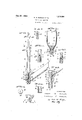
- Fig. 1 is a fragmentary detail verticalVV mid-sectional view of a nailer.
- Fig. 2 is a horizontall section through the nailer on line 2-2 of Fig. 1.
- Fig. 3 is a fragmentary detail vertical section similar to Fig. 1, in which the nailing tube is in a somewhat advanced downward position to illustrate the nail-selecting ⁇ action of this tube in relation to the nail-slide.
- Fig. 4 is a top plan view of the nailing tube.
- Fig. 5 is a fragmentary vertical cross-section on line 5 5 of Figs. 1 and2.
- Fig. 6 is a fragmentary vertical section on line 6 6 of Figs. 1 and 2.
- Fig. 7 is a fragmentary vertical section through the nailing tubev on line 7-7 of Figs. 2, 3 and 9.
- Fig. 8 isa fragmentary side elevation of the nailing tube as seen in thedirectionvof the arrow 8 in Fig. 9.
- Fig. 9 is a horizontal cross-section through the nailing tube on line 9 9 of Figs. 3, 7 and'S.
- Fig. 10 is a fragmentary* vertical midsectional view through a nailing unit, illustratinp,a the nailers in inoperative position.
- Fig. 11 is a fragmentary side elevation of the nailing unit in Fig. 10.
- Fig. 12 is a side elevation of a nailing unit, partly in section, illustrating the nailers in actuated position.
- Fig. 13 is a top plan view of a pair of engaging jaws for actuating the nailing unit when operatively engaged with the spindle of an electricy motor.
- Fig. 1A is a fragmentary diagrammatic illustration of an assembly of two nailing units in a frame structure with operating connections.
- Fig. 15 is a fragmentary perspective view of a control for the several nailersin a nailing unit. p r
- Fig. 16 is a fragmentary top plan View of three nailers in a unit, illustrating the sidewise spacing of the different nailers in a unit.
- Fig. 17 is a Vfragmentary side elevation of the upper end of a nailer, illustrating a slight modification of suspensibly supporting va nailing unit.
- Fig. 18 is a cross-.section on line 18-18 of Fig. 17.
- Fig. 19 is a fragmentary perspective view of several boards nailed together, illustrating three nails in a narrow board arranged closely together, and yanother three nails in a wider board spaced to quite an extent, and .showing also a corner-piec-e between two iside boards in which three single nails are indicated in off-set position.
- Fig. 2O is a side elevation of a hook to engage with the notches of the nailer-head illustrated in Fig. 4., serving also to hold the nailers down against the tension of the :springs 53 illustrated in Figs. 10 and 12.
- Fig. 21 is a fragmentary front elevation Aof a slightly modified arrangement of the operating levers and bars in connection with a nailer .and a nail-.box with other control- 'Sling means.
- Fig. 22 isa fragmentary perspective view Lof .engaging and controlling mechanism for tur-ning, :the different nai'lers for different 'positions to receive different nails, and serving to hold the nailers and other mechanism down against 'the tension of Athe springs 53 illustrated in Figs. 10 and 12, being a slightly modified form .over controlling means illustrated in Figs. 1, 2., 4t, 15 and 20.
- Thedierent side-boards, sla-ts, or spacing cleats, of such different boxes are quite 4commonly of very lmuch varying thicknesses.
- the nails ⁇ used in building up these boxes must therefore quite frequenty be of different lengths :in one and the same box, to assure a proper holding .
- a nailing machine vor apparatus to be really useful, lmust :therefore be designed to allow the use of diiferent nails .during one and the same action.
- Nails are furthermore not always in a straight line along the edge of boxes, Vas for instance,illustrated in Fig. 19, where a corner-piece 25 is disposed between the boards 26 and 27.
- a nail may be forced into the board 26 so as to be in alignment with other nails in the same board at a point indicated at 28, but it is desirable to have another r nail forced int-o the board 27 at a point indicated at 29, and eventually another nail into the corner-piece 25 indicated at 30, these three nails at the points 28, 29 and 30 being eventually forced through another slat or top or bot-tom board to firmly hold such a corner together.
- a nailing machine or apparatus must be designed to allow a slight shifting of the nailers to bring nails to such oil-set positions.
- a proportionally narrow slat or board is indicated at 31 in Fig. 19, in which the positions of three nails are indicated at 32.
- Another somewhat wider board is indicated at 33, having also the positions of three nails indicated as at 34.
- a nailing machine must be designed to allow a quick changing of the spaces in so-called gang-nailing.
- Boxes are made of so many different sizes and shapes and nails are driven into various positions in relation to one another that a nailing machine, to be really useful for efficient service, must allow a varying and changing and setting to quite an extent during one and the same operation on certain types of boxes, as will easily be understood from the above with reference to Fig. 19.
- a nailing unit of very effective and etlicient design is illustrated in Figs. 10, 11 and 12. Such a nailing unit is preferably provided with an individual motor right on top of the nailing unit, as indicated at 35.
- nailing units are, for such major-ity of boxes, sutlicient in a nailing machine.
- Such nailing units are .thenpreferably arranged near the two end standards 3G o-f a nailing machine, as illustrated in Fig. 14, a nailing unit being indicated near the opposite standards 36 at 37.
- the nailing units as illustrated in Figs. 10, 11 and 12, are provided with three separate and distinct nailers, as indicated at 3S. More or less nailers may, of course, be used in one unit.
- the motor 35 on top of each unit, is provided with a downwardly extending threaded shaft or spindle 39.
- the nailer-s of a nailing unit are suspended from a crosshead 40.
- Threaded blocks -11 are disposed in the cross-head 40. These threaded blocks .l1 are shiftable radially in relation to the spindle 39.
- a pair of threaded blocks are illustrated in top plan view.
- the centermost terminations a2 of the threaded blocks 41 are provided with threaded faces to engage with the spindle 39.
- Cams 43 are provided within the blocks 41, by which the threaded faces 42 may be forced into engagement with the spindle 39.
- FIG. 10 the threaded blocks 41 are illustrated in disengaged position, free from engagement with the spindle 39.
- An actuating member 44 is provided with notches 45 to engage with the cams k43 of the blocks 41.
- the cams 43 are located within the notches 45 of the actuating members, so that the blocks 41 may move outwardly away from the spindle, as illustrated in Fig. 10.
- the turning spindle 39 forces the threaded blocks, and therewith the cross-head with the suspended nailers 38, in a downward direc tion.
- the motors 35 on the several nailing units of a nailing machine of this type are preferably operated in a continuous manner when in use, so that the cross-head with the nailers can be made to move downwardly by the mere engagement of the threaded blocks with the spindle.
- a moving of the actuating ⁇ member 44 produces therefore an actuating of the nail Iers in a unit.
- the actuating member 44 has merely to be brought back to normal inoperative position, so that the threaded blocks may move outwardly away from the threaded spindle, with the cams 43 resting in the notches 45 of the actuating member.
- Springs 46 are provided for the threaded bloclrs by which the threaded blocks will be moved outwardly as soon as and whenever the cams 43 come into or are in alignment with the notches 45.
- the actuating member 44 is forced downwardly by bars 47 to bring the actuating member into operative position, while the actuating member is auto-V matically moved back to normal position when the nail drivers have driven the nails.
- the nailers when stopped in their downward movement, stop the downward moving actuating member 44, so that the still further downwardly moving cross-head with the threaded blocks tends to cause disengagement of the threaded blocks from the )indie 39, as soon as the cams 43 reach a point to come into alignment with the notches 45 of the stopped actuating member 44.
- the actuating member 44 is forced downwardly by the bars 47 to a posin tion as illustrated in Fig. 12, the threaded blocks 41 with the cross-head 40 and suspended nailers 39, move downwardly until the nailers reach the object on which nails are to be used.
- rlhe line 48 may illustrate the top surface of a bon. The nailers in this illustration are shown as resting on the top of the box.y
- the nailers are merely suspended on the cross-head 40.
- this is accomplished by a U-shaped member 49.
- the upright portions of the U-shaped member 49 are freely shiftable through the bottom flange 51 of the crosshead 40, so that the portions 50 may move through the flange 51 when the nailers come to a stop while the cross-head is still moving downwardly on the spindle 39.
- the upper block 56 forms so' to say the base for the whole structure of a nailing unit, being in fact, however, only relatively stationary with reference to the different moving parts in the nailing unit.
- rlhis block 56 is swingably and pivotally supported on the cross-head 59 of the main frame structure of the nailing machine as illustrated in Fig. 14.
- each nailing unit is preferably made as flexible as possible, that is, so that it may allow a turning movement to some extent axially, and so as to allow a swinging movement back and forth between the front and rear of the nailing machine and also a swinging CJI in a sidewise direction.
- rlwo nailing units are shown suspended from the cross-head in the main traine struct-ure. Oli' course more or less nailing units may be suspended vtrom such aY cross-head depending on the requirements in nailing actions with dit ferent bones.
- the several nailing ⁇ units may be Asupported from different points in the cross-head 59, such points being indicated at iin Fig. 14.
- Figs. 1.0, 11., and 12 the inain cross head 5.9 is illustrated in torni ci' two bare.
- the bolts 61 serve to swingably support the block 56 on the main cross-head 59.
- FIG. 17 A slightly modiiied form of connection is illustrated in Figs. 17 and 18,.
- rEhe block designated by the numeral 56a in this slightly modified form is provided with an annularly grooved neck 62.
- Fulcrum blocks 63 are disposed in this grooved neck 62, which are pi-votal'ly secured to the main cross-head 59 by the bolts 6l.
- the block 56a, and therewith Va whole nailing unit may be turned ⁇ around its axis, and swing .around the :pivot 61 in sidewise direction between the main standards
- the kmainmaj-head is provided with pins Getinits termi-nations by which the crosshead and therewith the whole nailing unit may be swung back and forth between the front and rear of the whole nailing n. achine, the ypivots being vindicated at 64; in 11 and lll.
- Each nailer in a 'nailing unit is provided with nail-supplyingand feeding means, nail-separating means., and a nailingplunger.. These main parts of a nailer are illustrated in detail in Figs. 1, 2 and 8.
- rThe nail-.supplying.and setting means of a ⁇ nailer consists of ⁇ an inclined block 65 with guideplates 66 provided along the opposite sides of vthe block 65, so as to torni spaces 67 tor nails to slide towards nail-separating- .points V68. Tlienpper edges of the guideplates 66 are provided with an off-set 69 by which nails are caused to assume a suit-ably inclined position as Aindicated in dotted lines at 70 in Fig'.
- Such -an advanced nail is separated and allowed rto drop into the nailing-tube 7l during ⁇ the upward rfi inovoinentot' the'nailing-tube.
- lhe nailingtube is provided with a separating' mear ber 72. and just above the separating effetber, with an opening 73.
- the advanced :and separated nail easily drops into the nailing-tube. as the opening .ot the nailing-tube .moves iurfther and .tur-
- the separating ine-inter 7 2 is coated so that no more nails can .pass into the nailing-tube, one nail being showin within the nailing-tube at 711 ready 'for the nailinp ⁇ action.
- the naiiing-tube On .ino-ving downwardly, the naiiing-tube :passes the ⁇ point where the heads of the nails tend to advance first, before the separatin-i;- member 72 frees the nails in the nail-,guides for advancement, the nailing-tube .tending?, ⁇ to shut off Va passing, ot nails from the nail-guide 65 into the nailing-tube as indicated at in Fig. 8.
- i plunger 76 illustrated in Fig. 1, is provid-ed to drive the vnail 74 out of the Ynailing-tube at a proper time, as will be more fully .described hereafter.
- Ii guiding member 77 is provided on th naihguide 65 in which the nailing-tube 7l may nieve up and down as described above.
- the nail-guide is illustrated Vas lnivingv two i'iaihguiding spaces 67. More or less of course, be provided tor each naili tube.
- the nailing-tube is disposed turnably .vitliin the .guiding member .7 7 so that the opening 73 and the nail-separating ineinber 72 can move up and down in suitable relation to any ot such nail-guiding spaces.
- the nailing-tube in Fig'. 2 the nailing-tube is sho-wn in neutral inoperative position, the nail-separating member 72 being disposed in a blank groove between the two nailguiding spaces 67, so that on an up and down moving ot' the nailing-tube no ⁇ nail can ,pass from either of the nail-guiding spaces :through the opening ⁇ 73 into the nailing-tube 71 when the nailing-tube is so disposed.
- A. yieiding' engagement is provided between fthe nailing-tube 7-1 and the guiding' member 77 indicated .at 78 in Figs. l and 2".
- rilie sprine' upported yielding key or plugr 78 may engage with any of the grooves 79 to guide the tube in a certain relation to the nail-supplyiney guides ot the block 65.
- This yielding ⁇ engagement can easily be overcome by a lsuitable turni-ng of the The head 8O oit.' the tube 7l is promi ed with suitable notches 81, illustrated in Fig. et, by which suitable mechanism may be aiplied for turning' :the tube. lf not forcefully turned, the tube 71 is normally such guiding; spaces for nails can,
- the rear end 83 of the bloek 65, illustrated in Figs. 1 and Q, is prei'erably pivotally supported in the Jran'ie 84h illustrated in Fig. 15, at anyY one ot' the points indicated at 85.
- Any desired number olf nailers may be combined into a .nailing unit Within such a frame 94, three nailingtubes being roughly outlined at 71 in Fig. 15, but it Will easily be understood that more or less nailing-tubes and therewith complete nailers can be disposed in such a trame. ln lFig. 16, three complete nailers are outlined as indirated'at 90, pivotally supported on the bar 87 ot the l'iame 84, in Fig. 15.
- rEhe outeremost nailers in a unit can be swung around their pivots to the positions indicated in dotted lines at 88 in 16, so that t-he nailers in a unit may be operated with various spaces between the dillerent nailers.
- Spacing bars S9 are provided for controllingl lthe spacing actions ot' the nailing-ends of the nailers in a unit.
- Wedge members 90 are provided 'for forcing the spacing bars 89 apart, and springs 91 are provided tor bringing the nails back to and for holding the nailing members in their normal closest position in relation to one another.
- llail containers 92 are pivotally connected at 93 to the nail-guides G5, as illustrated in Fig. 14, through the connections 93. r1 ⁇ he nail containers are connected with the actuating' rod 47V so that ⁇ a suitable shaking ot the containers 92 is accomplished on each actuating ot the rod 47.
- rlhe bars 89 are provided With suitable perlorations or slots 95 for pins by which A the loiver tree ends of the nailing units may be limited in their lswinging movements.
- il spring 9G is illustrated by which oppositely arranged nailing units may be held against su'inging movements, When so resting against pins in the pertorations or slots 95 of the bur 89.
- the several mechanisms in this nailing nacliine may be actuated by 'footpedals or levers not shown in the drawing, through several independent or interconnected conneetions or connecting rods. Since principally 'lor pulling actions, the connections ma easily be oit flexible material as, tor instance, ot wire cables or other similar suitable material.
- rlhe connections 97 are provided for moving the nailing units outwardly against the tension ot' the springV 9G, so that a so-called gang-nailing may be accomplished along the two opposite edges of a box With'slightly varying spacing from the edge of the box or between the oppositely arranged nailing units 4during the continuous nailing operation in connection with such a box. This arrangement allows a quick Vchanging of the position of the nailing units during the operation.
- connections 99 are provided for actuating the bars 47,.and thereby the nailing units for the nailing actions, and incidently actuating the nail containers.
- the several nailers 38 are suspended from the lower flange 51 of the shittable cross-head 40, and the 'upright portions 50 of the supporting member 49 extend 'shif'tably through the lower flange of the cross-head 40.
- rlhere are certain abutments 1n the term oia nuts or flanges 100 on the upper ends of the upright portions 50 resting on the top surface ot the lange 51, by which the nailers 38 are supported When so suspended from the cross-head 40.
- the plunger-stems 76 of the several nailers are provided with heads 101, by which these plungers are suspended from the lower -flange 51 ot the cross-head 40.
- These heads 101 areV illustrated in Fig. 1 withbeveled edges 102, but may as Well have squarely cut edges as long as'such edges allow a shifting in corresponding members or flanges 103 on the under side 01"' theV flange 51 of the cross-head 40, such flanges being indicated in Figs. 10 and 12.
- the heads 101 must be: shittable in the under 'side of the flange 51 for the reason ,y
- nailers are also shiftably suspended to allow a variation in the spacing of the outer-most nailers by the bars 89, as described above.
- the nailing-tubes 71 are provided With abutting shoulders as indicated at 104 in Figs. 1 and 10, to be shiftable vWithin the slot 105 in the U-like supporting member 49;
- the cross-head moves still further downwardly, the plungers go into the nailing-tubes of the nailers 38, thereby performingthe nailing action as described above, until the ends 52 ol the. actuating members 44 ycome into contact with the then upper ends 100 of the supporting' member 49.
- the upper 'ends 100 ol the supportingl member 49 serve to disengage the threaded blocks 41 Yfrom the motor spindle 39, as the lower ends 52 ol the actuating member 44 are stopped in. their downward movement by the upper ends ol the supporting member 49.
- the threaded blocks, and therewith the whole nailing unit, is automatically disengaged from the continuously rotating motor spindle 39 on each completion of a nailing action of the nailers as described above.
- the actuating ⁇ member 44 will come into Contact with the bars 47 il the saine are in depressed position.
- the dowrn'vardly7 extendingv ends 52 are forced into the upper end of the crosshead, so as to again move the threadet blocks inwardly or centrally into closet. position.
- the spindle is threaded lr'oin its free end upwardly to a point indicated at 106, this being a. point. below the threaded blocks in their upper-most position.
- the cross-head 40 with the suspended unit of nailers is suitably pressed downward to such an extent that the threaded blocks will be moved into engagement with the threaded portion of the spindle at the point 10S. ⁇
- a continuous nailing with automatically repeated downward actions may be accomplished by a setting ol' thel rods or bars 47 in a depressed position so that the threaded blocks will engage the threaded portion of the spindle every time the cross-head 40 reaches its upper-most position on the spindle.
- the hook-like member 109 illustrated in Fig. 20, is designed to engage with the notches 81 of the head S0 or the nailers, a pin 118 is provided on the top head of each of the nailers in the slightly modilied form illustrated in Fig.
- the operation of the hooks 109 in conjunction with the notches S1 may easily be understood from the description of the mechanism illustrated in Fig. 22.
- the nailers are turnably disposed in the guiding block 77 and so controlled that nails ol' different sizes or ditler-ent types may be supplied through the opening 73 of the nailers by setting or turning the nailers to the dil'erent positions described with reference to the illustration in Fig. 2.
- SuchL a turning can, oi' course, be accomplished just as well by actuating the nailers through the pins 113 as illustrated in Fig. 22.
- rlhe shaft 107 is turnably and shi'ftably journaled at 115.
- Engaging lingers 110 are adjustably mounted on the shaft 1.07.
- the shaft 107 is therefore threaded as indicated at 1075,L to allow a sidewise adjustment in relation to the vertical axes of thc nailers, longitudinally on the shaft 107.
- a shifting ol' the shaft 107 in axial direction causes a turning of the nailers by the pin 113 since the pin 113 is disposed between a pair-ot fingers 116.
- hooks 109 While the hooks 109, illustrated in F 20, serve at the same time to also hold down the member 49 on which the nailers are suspended, in the modified form illustrated in Fig. 22 extra hooks 117 are provided to hold the supporting member 49 down while the engaging or actuating fingers 116 produce a turning movement of the nailers only.
- the shalt 107 is turnably mounted to allow a disengagingr ol the hooks 109 or the hooks 117 fl'rom the supporting member 40, with the form illustrated 1n Figs. 15 and 20.
- a turning ot the shaft 107 serves to brine' the hooks V109 into engagement with tha notches 81 as well as to engage over the supporting member 49. while a turning of the shaft 107 in the slightly modified lorm illustrated in Fig. 22 serves to bring the hooks 117 into engagement over the supporting member 49 by the cams 118 on the shaft 107. the engaging and actuating nngers 110 at the same time engaging over the fingers 113 et the nailers. il lever 108 is provided to actuate the shaft 107.
- the actuating ot .the shaft 1Q? may be fully manual or a spring 119 may be provided to help m disengaging and normally holding the hooks and thereby the shaft with the engaging and actuating fingers 11G in normal inoperative position in relation to the nailers and nail-supporting ⁇ members 49.
- the spindle 39 is made to extend into the hollow ol" the cross-head i0 tor lubricating this spindle. rthe cross-head is maintained full oi' the lubricant so that the spindle continuously lubricated by returning to normal position within the Crosshead.
- nailers disposed tor back and forth movements, an actuating motor having a threaded spindle, and a nailing unit carrying said nailers having means for engaging the spindle 'during a nailing ⁇ action and adapted for disengagement from the threaded spindle on completion ot the nailing action.
- a nailing machine of Athe class described a frame struct-ure, a plurality of nailing mechanisms suspended from the frame structure, each nailing mechanism consisting ot several nailers, an individual motor tor each of the said mechanisms, a cross-head shiftably disposed in the direction of suspension, engaging ⁇ means between the said cross-head and the said motor in each of the mechanisms, means tor engaging the engaging means with the motor for actuating the cross-head in a, downward direction adapted to release the cross-head on completion ot, its downward movement, means for automatically returning the crosshead with the nailers to the upper-most normal and inoperative position, the several nailers in a mechanism including nail helders suspended trom the said cross-head by means adapted to allow a 'downward movement et the cross-head while the suspended nail holders have come to a stop, and nailing plungers suspended from the cross-head adapted to move into the nail holders when the nail holders come to a stop while the crosshead is still moving ⁇ downwardly.
- a nailing machine ot the class described, a trame structure, a plurality of nailing mechanisms suspended from the frame structure, each nailing mechanism consisting ot several nailers, an mdlvldual motor for each of the Ysaid mechanisms, a
- cross-head shiftably disposed in the direction ot suspension, engaging means between the said cross-head and the said motor in each of the mechanisms, means for engaging the engaging means with theV motor tor actuating the cross-head in a downward direction, means for automatically returning the cross-head with the nailers to the upper-most normal and inoperative'position, the several nailers in a mechanism includingnail holder suspended from the said cross-head by means adapted to allow a downward movement of the cross-head while the suspended nail holders have come to ya stop, nailing plungers suspended from the crosshead adapted to move into the nail holders when the nail holders come to a stop while the cross-head is still moving downwardly, and means controlled by the nailers for disengaging the motor-engaging means.
- a nailing machine ot the class described, a nailer consisting ot a reciprocable nailing tube having an opening in one longitudinal side and having a nail-separating member projecting outwardly in a radial direction from the tube and extending from the opening downwardly, a nail-supplying guide having a plurality of guideways for nails, the said nail-supplying guide having passageways for the said nail-separating member in relation to each of the guideways and in a neutral position so that the nailing tube with the nail-separating member may pass up and down in front of the nail-guidewaysas well as in an Vinoperative position away from the nail-supplying guideways, means for setting the nailing tube shiftable within the nail-supplying guide in relation to the one o1c the guideways and the neutral position, and a nailing plunger disposed in vthe nailing tube.
- G. ln a. nailing machine of the class described, an electric motor having a threaded spindle pointing in a downward direction, a frame structure, a nailing unit disposed in the 'frame structure below and in alignment with the said spindle, and means for engaging the nailing unit with the threaded spindle during a nailing action adapted to release the nailing unit to permit the same to return to normal inoperative position at the completion thereof.
- a nailing mechanism consisting ot' several nailers vith nail-supplying means, a supporting trame, a plurality ot' nail-supplying guides pivotally supported by the said trame, nailing tubes shittably disposed in the tree-swinging ends ot the nail-supplying guides for movements in up and down directions, nailing plungers in each of the nailing tubes, the axes of the several plungers being practically parallel in the several nailers to one another, and means t'or controlling the freely swingingends ot the nail-supplying guides so as to hold the nailers spaced in a desired relation to one another.
- a main trame a plurality ot' independent nailing mechanisms each embodying an individual electric motor a-nd nailers actuated thereby, flexible connections suspending said mechanisms in the frame' and adjustable therein, bars yieldingly supported on the main trame for guiding the lower tree ends ot the mechanisms and tor determiningthe lateral spacing of the nailers, members to actuate and control said bars, and controls for governing said mechanisms in their normal operations of feeding and driving nails.
- nailing mechanisms disposed for universal movements, actuating motors having tlir aded spindles, and nailing units having means for engaging the spindle-s during a nailing action and adapted to be disengaged from the threaded spindles on completion of the nailing action.
- a plurality ot individually electrically motor-driven nailing mechanisms In a box-nailing machine, a plurality ot individually electrically motor-driven nailing mechanisms, a main trame structure, and means for universally suspending nailing mechanisms within the main frame structure.
- a plurality of individually electrically motor-driven nailing mechanisms a main trame structure, means for universally suspending nailing mechanisms within the main tramev structure, and means for controlling the lower ircely swinging ends ot' the mechanisms in the main trame structure.
- a trame structure a plurality of nailing mechanisms universally suspended from the trame struc-- ture, each nailing mechanism consisting ot one or more nailers, an individual motor for each ot the said mechanisms, a cross-head shittably disposed in the direct-ion ot suspension, engaging means between the said cross-head and the said motor in eacii ott the mechanisms, means for engaging the engaging means with the motor tor actuating the cross-head in a downward direction adapted to release the cross-head on completion of its downward movement, means tor automatically returning the cross-head with the nailersto the upper-most normal and inoperative position, the one or more nailers in a mechanism having' nail-holders suspended from the said cross-head by means adapted to allow a downward movement of the crosshead while the suspended nail-holders have come to a stop, nailing plungers suspended from the cross-head adapted to move into the nail-holders when the nail-holders come to
- a trame structure a plurality of nailing mechanisms suspended from the trame structure, each nailing mechanism consisting ot' one or several nailers, an individual motor for each or" the said mechanisms, a cross-head shi'litably disposed in the direction ot' suspension, engaging means between the said cross-head and the said motor in each ot the mechanisms, means tor engaging the engaging means with the motor for actuating ⁇ the crosshead in a downward direction, means for automatically returning the cross-head with the nailers to the upper-most normal and inoperative position, the several nailers in a.
- nail-holders suspended from the said cross-head by means adapted to allow a downward movement of the crosshead while the suspended nail-holders have come to a stop
- nailing plungers suspended from the cross-head adapted to move into the nail-holders when the nail-holders come to a stop while the cross-head is still moving downwardly'
- means controlled by the nailers tor disengaging the motor-engaging means means to feed nails to the several nail holders in a mechanism, and means to control the feeding of said nails.
- an electric motor having a threaded spindle pointing in a downward direction, a frame structure, a nailing unit suspended in the trame structure below and in alignment with 'the said spindle, and means for engaging the nailing unit with the threaded spindle during a nailing action adapted to release the nailing unit to permit the same to return to normal inoperative position.
- a nailing mechanism consisting of one or more nailers, nail-supplying means, a supporting trame, a plurality of nail-tube guides pivotally supported by the said trame, nailing tubes shi ttably disposed in the tree-swinging ends ot' the nail-tube guides for movements in up and down directions, nailing plungers in each of the nailing tubes, the axes oi the several plungers being practically parallel in the several nailers to one another, and means for controlling the freely swinging ends ot the nail-tube gnides so as to hold the nailers spaced in a desired relation to one another.
- a main trame a nailing mechanism universally suspended in the main trame, a cross-head shift-able within the nailing mechanism, actuating means for the cross-head, nailers'suspended from llO the cross-head in operative connection therewith, and interengaging means between the cross-head and the actuating means adapted to free the cross-head when the nailers contact with work.
- a nailing machine a main frame, and a nailing mechanism embodying actuating and actuated means, and including naiiers suspended from the actuated means, interengaging, ⁇ means between the actuated means and the actuating means in operative connection with the nailers adapted to free the actuated means from the actuating means when the nailers contact with work, and neutralizing means for returning the naiiers and their supporting actuated means upwardly when the actuated means are so freed.
- a power-actu ated cross-head or the like guided member with nail-driving mechanisms attached thereto and operated thereby means to disengage said cross-head from its actuating power during its downward movement upon contact of the nailers with the work, and
Landscapes
- Engineering & Computer Science (AREA)
- Mechanical Engineering (AREA)
- Life Sciences & Earth Sciences (AREA)
- Forests & Forestry (AREA)
- Dovetailed Work, And Nailing Machines And Stapling Machines For Wood (AREA)
Description
Feb. 23 192s. 1,574,490
H. R. KUMLER ET AL BOX MAILING MACHINE Filed Deo. 4, 1924 4 Sheets-Sheet 1 Feb. 23 1926.
H. R. KUMLER r-:T AL
BOX NAILING MACHINE Filed Dec. 4, 1924 :FIB: 1D., Email.
. 5b 56 59 A 64 64 w 59 6 55 E/:B if? E2? 13j HL2 4A l @i 54 J I i 5215 405 49 sa f/ 95 90 /g CRHOLL 4 Sheets-Sheet 2 /NvENroRSu KUN/ 512,
F.' UML/51e,
Feb. 23 1926.
H. R. KUMLER ET AL.
BOX NAILING MACHINE Filed DGC- 4, 1924 4 Sheets-Sheet 5 cr. BEI.
INVENTGRS:
Feb. 23 1926.l 1,574,490
H. R. KUMLER ET AL BOX NAILING MACH NE Filed DSC- 4, 1924 4 Sheets-Sheet 4.
IN VEN TOFZS.'
Hams/Ey E?. Kun/.512',
CARROLL FI /n/MLER,
'y Mm Fatenteel Feb. 23, 1925.
UNHTED PA'E'ET OFFICE.-
HERVEY R. KUMLER AND CARROLL F. KUMLER, OF LGS ANGELES, CALIFORNIA'.
BOX-Marmite MACHINE.
Application mea December 4, 1924. serial No. 753,873.
To all whom t may concern:
Be it known that we, HnRvnY R. KUMLER and CARROLL F. KUMLER, citizens of the United States, residing at Los Angeles, in the county of Los Angeles and State of California, have invented a new and useful BoX-Nailing Machine, of which thefollowing is a specification.
This invention relates to devices for assembling and nailing bones.
One of the objects of this invention is to provide a device or machine in which the different nailing mechanism are operated by individual electric motors.
Another object is to provide a plurality of individually operated nailing units suspended at their upper ends in a common main frame `so that the lower ends of the different nailing units can be moved in any direction away from their center line of gravity.
Another object is to provide a plurality of individually operated nailing units suspended within the main frame, embodying 'controlling mechanism by which the lower free ends can be controlled in certain positions in relation to the work to be performed.
Another object is to provide a threaded stem or spindle on an electric motor by which a nailing mechanism can be forced downwardly when operatively engaged with the threaded spindle of such electric motor.
Another object is to provideV a plurality of nailers within a nailing unit by which several nails may be driven by one operation of such unit.
Another object is to provide mechanism by which several nailers in a unit can be controlled in certain spaced relation to one another, so that nails may be driven by such a unit with various spaces between the nails. n
Another' object is to provide mechanism by which nails can be automatically placed with varying spacing, by one and the `same nailing unit during the operation with a nailing machine.
Another object is to provide a nailhfeeding mechanism by which various nails may be used in the dierent nailers of a nailing unit during a continuous operation of a nailing machine.
Another object is to provide several nailers in one unit embodying means by which any of the nailers in the unit may be moved to and held in neutral, inoperative, or not-nailing position, while other nailers in the unit perform regular nailing actions.
@ther objects will appear from the following 'description and appended claims, as well as from the accompanying drawings, in which Fig. 1 is a fragmentary detail verticalVV mid-sectional view of a nailer. i
Fig. 2 is a horizontall section through the nailer on line 2-2 of Fig. 1.
Fig. 3 is a fragmentary detail vertical section similar to Fig. 1, in which the nailing tube is in a somewhat advanced downward position to illustrate the nail-selecting` action of this tube in relation to the nail-slide.
Fig. 4 is a top plan view of the nailing tube. n
Fig. 5 is a fragmentary vertical cross-section on line 5 5 of Figs. 1 and2.
Fig. 6 is a fragmentary vertical section on line 6 6 of Figs. 1 and 2.
Fig. 7 is a fragmentary vertical section through the nailing tubev on line 7-7 of Figs. 2, 3 and 9.
Fig. 8 isa fragmentary side elevation of the nailing tube as seen in thedirectionvof the arrow 8 in Fig. 9.
Fig. 9 is a horizontal cross-section through the nailing tube on line 9 9 of Figs. 3, 7 and'S.
Fig. 10 is a fragmentary* vertical midsectional view through a nailing unit, illustratinp,a the nailers in inoperative position.
Fig. 11 is a fragmentary side elevation of the nailing unit in Fig. 10.
Fig. 12 is a side elevation of a nailing unit, partly in section, illustrating the nailers in actuated position.
Fig. 13 is a top plan view of a pair of engaging jaws for actuating the nailing unit when operatively engaged with the spindle of an electricy motor.
Fig. 1A is a fragmentary diagrammatic illustration of an assembly of two nailing units in a frame structure with operating connections.
Fig. 15 is a fragmentary perspective view of a control for the several nailersin a nailing unit. p r
Fig. 16 is a fragmentary top plan View of three nailers in a unit, illustrating the sidewise spacing of the different nailers in a unit.
Fig. 17 is a Vfragmentary side elevation of the upper end of a nailer, illustrating a slight modification of suspensibly supporting va nailing unit.
Fig. 18 is a cross-.section on line 18-18 of Fig. 17.
Fig. 19 is a fragmentary perspective view of several boards nailed together, illustrating three nails in a narrow board arranged closely together, and yanother three nails in a wider board spaced to quite an extent, and .showing also a corner-piec-e between two iside boards in which three single nails are indicated in off-set position.
Fig. 2O is a side elevation of a hook to engage with the notches of the nailer-head illustrated in Fig. 4., serving also to hold the nailers down against the tension of the :springs 53 illustrated in Figs. 10 and 12.
Fig. 21 is a fragmentary front elevation Aof a slightly modified arrangement of the operating levers and bars in connection with a nailer .and a nail-.box with other control- 'Sling means.
Fig. 22 isa fragmentary perspective view Lof .engaging and controlling mechanism for tur-ning, :the different nai'lers for different 'positions to receive different nails, and serving to hold the nailers and other mechanism down against 'the tension of Athe springs 53 illustrated in Figs. 10 and 12, being a slightly modified form .over controlling means illustrated in Figs. 1, 2., 4t, 15 and 20.
To 'facilitate a shipping of fruit, vegetables, and the like, it has been found necessary to provide certain types and shapes of boxes for certain articles to avoid a damaging of such fruit and the like during transportation.
'Some boxes are closed on all sides. Other boxes have lend-boards :and on yall other sides only slats. Still other boxes have cleats nailed :over the top or on `the bottom to space the boxes when arranged one on top .of the other.
Thedierent side-boards, sla-ts, or spacing cleats, of such different boxes are quite 4commonly of very lmuch varying thicknesses. The nails `used in building up these boxes must therefore quite frequenty be of different lengths :in one and the same box, to assure a proper holding .together of the box Iwhen such nails are forced through the several boards and slats and cleats of different thicknesses. A nailing machine vor apparatus, to be really useful, lmust :therefore be designed to allow the use of diiferent nails .during one and the same action.
Nails are furthermore not always in a straight line along the edge of boxes, Vas for instance,illustrated in Fig. 19, where a corner-piece 25 is disposed between the boards 26 and 27. A nail may be forced into the board 26 so as to be in alignment with other nails in the same board at a point indicated at 28, but it is desirable to have another r nail forced int-o the board 27 at a point indicated at 29, and eventually another nail into the corner-piece 25 indicated at 30, these three nails at the points 28, 29 and 30 being eventually forced through another slat or top or bot-tom board to firmly hold such a corner together. To accomplish such an off-setting, a nailing machine or apparatus must be designed to allow a slight shifting of the nailers to bring nails to such oil-set positions.
A proportionally narrow slat or board is indicated at 31 in Fig. 19, in which the positions of three nails are indicated at 32. Another somewhat wider board is indicated at 33, having also the positions of three nails indicated as at 34. To accomplish such different spacing as illustrated at 32 and 34:, a nailing machine must be designed to allow a quick changing of the spaces in so-called gang-nailing.
Boxes are made of so many different sizes and shapes and nails are driven into various positions in relation to one another that a nailing machine, to be really useful for efficient service, must allow a varying and changing and setting to quite an extent during one and the same operation on certain types of boxes, as will easily be understood from the above with reference to Fig. 19.
A nailing unit of very effective and etlicient design is illustrated in Figs. 10, 11 and 12. Such a nailing unit is preferably provided with an individual motor right on top of the nailing unit, as indicated at 35.
In the majority of boxes, nails are driven in two parallel lines along the opposite edges of a box. riwo nailing units are, for such major-ity of boxes, sutlicient in a nailing machine. Such nailing units are .thenpreferably arranged near the two end standards 3G o-f a nailing machine, as illustrated in Fig. 14, a nailing unit being indicated near the opposite standards 36 at 37.
The nailing units, as illustrated in Figs. 10, 11 and 12, are provided with three separate and distinct nailers, as indicated at 3S. More or less nailers may, of course, be used in one unit.
The motor 35, on top of each unit, is provided with a downwardly extending threaded shaft or spindle 39. The nailer-s of a nailing unit are suspended from a crosshead 40. Threaded blocks -11 are disposed in the cross-head 40. These threaded blocks .l1 are shiftable radially in relation to the spindle 39.
In Fig. 13, a pair of threaded blocks are illustrated in top plan view. The centermost terminations a2 of the threaded blocks 41, are provided with threaded faces to engage with the spindle 39. Cams 43 are provided within the blocks 41, by which the threaded faces 42 may be forced into engagement with the spindle 39.
ln Fig. 10 the threaded blocks 41 are illustrated in disengaged position, free from engagement with the spindle 39. An actuating member 44 is provided with notches 45 to engage with the cams k43 of the blocks 41. In inoperative position, the cams 43 are located within the notches 45 of the actuating members, so that the blocks 41 may move outwardly away from the spindle, as illustrated in Fig. 10.
l/Vhen the actuating member is moved away from this inoperative position, the cams 43 are forced centrally towards the spindle, so as to engage operatively with the spindle, as illustrated in Fig. 12.
lli/Then the threaded blocks 41 are in their center-most or operative position, the turning spindle 39 forces the threaded blocks, and therewith the cross-head with the suspended nailers 38, in a downward direc tion.
The motors 35 on the several nailing units of a nailing machine of this type are preferably operated in a continuous manner when in use, so that the cross-head with the nailers can be made to move downwardly by the mere engagement of the threaded blocks with the spindle.
A moving of the actuating` member 44 produces therefore an actuating of the nail Iers in a unit.
To stop the movement of a nailer, or of nailers, in a unit, the actuating member 44 has merely to be brought back to normal inoperative position, so that the threaded blocks may move outwardly away from the threaded spindle, with the cams 43 resting in the notches 45 of the actuating member.
As illustrated, the actuating member 44 is forced downwardly by bars 47 to bring the actuating member into operative position, while the actuating member is auto-V matically moved back to normal position when the nail drivers have driven the nails. The nailers when stopped in their downward movement, stop the downward moving actuating member 44, so that the still further downwardly moving cross-head with the threaded blocks tends to cause disengagement of the threaded blocks from the )indie 39, as soon as the cams 43 reach a point to come into alignment with the notches 45 of the stopped actuating member 44.
lVhenever the actuating member 44 is forced downwardly by the bars 47 to a posin tion as illustrated in Fig. 12, the threaded blocks 41 with the cross-head 40 and suspended nailers 39, move downwardly until the nailers reach the object on which nails are to be used.
Such a condition is illustratedinFig. 12. rlhe line 48 may illustrate the top surface of a bon. The nailers in this illustration are shown as resting on the top of the box.y
As stated, the nailers are merely suspended on the cross-head 40. In the drawing, this is accomplished by a U-shaped member 49. The upright portions of the U-shaped member 49 are freely shiftable through the bottom flange 51 of the crosshead 40, so that the portions 50 may move through the flange 51 when the nailers come to a stop while the cross-head is still moving downwardly on the spindle 39.
is the cross-head 40 moves downwardly, while the nailers with the. liv-shaped member 49 and uprights 50 have come to` a stop, the downward-pointing ends 52 of the actuating member 44 come into contact with the upright ends 50, so that the actuating member 44 may be stopped in its downward movement thereby causing a neutralizing or disengagement of the threaded bloc-ks 41 in relation to the spindle 39, as described above.
llVhenever the threaded blocks are disengaged from the spindle 39, the whole cross-head with the suspendedv nailers, as a unit, is moved upwardly by the force of the springs 53. Springs 53 are disposed on the bolts 54 below the lower flanges 51 of the cross-head 40. The upper ends 55 of the bolts 54 are suspended from the stationary block 56, on which the motor 35 is mounted. The lower ends 57 of the bolts 54 support the guiding block 58 for the several nailers 33. The guiding block 58 is therefore somewhat stationary in this structure. The spring 53 is disposed between this relatively stationary guiding block'53 and the shiftable and movable cross-head 40.
The upper block 56, above-called stationary block, forms so' to say the base for the whole structure of a nailing unit, being in fact, however, only relatively stationary with reference to the different moving parts in the nailing unit.
The pivot connection or support for each nailing unit is preferably made as flexible as possible, that is, so that it may allow a turning movement to some extent axially, and so as to allow a swinging movement back and forth between the front and rear of the nailing machine and also a swinging CJI in a sidewise direction. rlwo nailing units are shown suspended from the cross-head in the main traine struct-ure. Oli' course more or less nailing units may be suspended vtrom such aY cross-head depending on the requirements in nailing actions with dit ferent bones. The several nailing` units may be Asupported from different points in the cross-head 59, such points being indicated at iin Fig. 14.
In Figs. 1.0, 11., and 12, the inain cross head 5.9 is illustrated in torni ci' two bare. The bolts 61 serve to swingably support the block 56 on the main cross-head 59.
A slightly modiiied form of connection is illustrated in Figs. 17 and 18,. rEhe block designated by the numeral 56a in this slightly modified form is provided with an annularly grooved neck 62. Fulcrum blocks 63 are disposed in this grooved neck 62, which are pi-votal'ly secured to the main cross-head 59 by the bolts 6l. lith this slightly modifiedA torni, the block 56a, and therewith Va whole nailing unit, may be turned `around its axis, and swing .around the :pivot 61 in sidewise direction between the main standards The kmain crois-head is provided with pins Getinits termi-nations by which the crosshead and therewith the whole nailing unit may be swung back and forth between the front and rear of the whole nailing n. achine, the ypivots being vindicated at 64; in 11 and lll.
Each nailer in a 'nailing unit is provided with nail-supplyingand feeding means, nail-separating means., and a nailingplunger.. These main parts of a nailer are illustrated in detail in Figs. 1, 2 and 8. rThe nail-.supplying.and setting means of a `nailer consists of `an inclined block 65 with guideplates 66 provided along the opposite sides of vthe block 65, so as to torni spaces 67 tor nails to slide towards nail-separating- .points V68. Tlienpper edges of the guideplates 66 are provided with an off-set 69 by which nails are caused to assume a suit-ably inclined position as Aindicated in dotted lines at 70 in Fig'. .3, so that a nail-separator can easily move in between such an advanced nailA andthe next following. Such -an advanced nail is separated and allowed rto drop into the nailing-tube 7l during` the upward rfi inovoinentot' the'nailing-tube. lhe nailingtube is provided with a separating' mear ber 72. and just above the separating neinber, with an opening 73.
As illustrated in Fig. 3, in its upward movement, `the 'hole or opening,- 7 3 in the nailing-tube '71, approaches the advanced nail at 7 2 first, so that the advanced nail is tree to swing further forward with its point in the direction towards the nailing-tube, ,that is, into the opening 73. This action facilitates a separating lot the nails, in pair- .ticu'lar a separating of the advance-d nail from the rest, so that the separating inembe-r 72 .easily moves behind the advanced nail in its upward movement.
The advanced :and separated nail easily drops into the nailing-tube. as the opening .ot the nailing-tube .moves iurfther and .tur-
ther upwardly past the position in which the advanced nail was resting, until the nailingf-tube 71 reaches' about the position as illustrated in Fig. 1. ln this normal inoperative position, the separating ine-inter 7 2 is coated so that no more nails can .pass into the nailing-tube, one nail being showin within the nailing-tube at 711 ready 'for the nailinp` action.
On .ino-ving downwardly, the naiiing-tube :passes the `point where the heads of the nails tend to advance first, before the separatin-i;- member 72 frees the nails in the nail-,guides for advancement, the nailing-tube .tending?,` to shut off Va passing, ot nails from the nail-guide 65 into the nailing-tube as indicated at in Fig. 8.
i plunger 76, illustrated in Fig. 1, is provid-ed to drive the vnail 74 out of the Ynailing-tube at a proper time, as will be more fully .described hereafter.
in Fig'. 2 the nailing-tube is sho-wn in neutral inoperative position, the nail-separating member 72 being disposed in a blank groove between the two nailguiding spaces 67, so that on an up and down moving ot' the nailing-tube no `nail can ,pass from either of the nail-guiding spaces :through the opening` 73 into the nailing-tube 71 when the nailing-tube is so disposed.
A. yieiding' engagement is provided between fthe nailing-tube 7-1 and the guiding' member 77 indicated .at 78 in Figs. l and 2". rilie sprine' upported yielding key or plugr 78 may engage with any of the grooves 79 to guide the tube in a certain relation to the nail-supplyiney guides ot the block 65. This yielding` engagement, however, can easily be overcome by a lsuitable turni-ng of the The head 8O oit.' the tube 7l is promi ed with suitable notches 81, illustrated in Fig. et, by which suitable mechanism may be aiplied for turning' :the tube. lf not forcefully turned, the tube 71 is normally such guiding; spaces for nails can,
lll
guided in one ot the grooves 9 to bring the opening 73 and the nail-separating member 72 into alignment witha desired nail-guiding space in the nail-supplying block or with the neutral groove 82 illustrated in Fig. 2.
rThe rear end 83 of the bloek 65, illustrated in Figs. 1 and Q, is prei'erably pivotally supported in the Jran'ie 84h illustrated in Fig. 15, at anyY one ot' the points indicated at 85. Any desired number olf nailers may be combined into a .nailing unit Within such a frame 94, three nailingtubes being roughly outlined at 71 in Fig. 15, but it Will easily be understood that more or less nailing-tubes and therewith complete nailers can be disposed in such a trame. ln lFig. 16, three complete nailers are outlined as indirated'at 90, pivotally supported on the bar 87 ot the l'iame 84, in Fig. 15.
rEhe outeremost nailers in a unit can be swung around their pivots to the positions indicated in dotted lines at 88 in 16, so that t-he nailers in a unit may be operated with various spaces between the dillerent nailers.
Spacing bars S9 are provided for controllingl lthe spacing actions ot' the nailing-ends of the nailers in a unit. Wedge members 90 are provided 'for forcing the spacing bars 89 apart, and springs 91 are provided tor bringing the nails back to and for holding the nailing members in their normal closest position in relation to one another.
'lhe rods 47 are held in their upper normal and inoperative position by the springs 94.
rlhe bars 89 are provided With suitable perlorations or slots 95 for pins by which A the loiver tree ends of the nailing units may be limited in their lswinging movements. il spring 9G is illustrated by which oppositely arranged nailing units may be held against su'inging movements, When so resting against pins in the pertorations or slots 95 of the bur 89.
The several mechanisms in this nailing nacliine may be actuated by 'footpedals or levers not shown in the drawing, through several independent or interconnected conneetions or connecting rods. Since principally 'lor pulling actions, the connections ma easily be oit flexible material as, tor instance, ot wire cables or other similar suitable material.
Considering the possibilities of neutralizing any movement ot the nailers in a unit, it must also be understood that from a gang-nailing along the edges of4 the box, the machine can thus quickly be changed to single olii-set nailing indicated at 2S, 29 and 30, in Fig. 19, during the continuous normal operation ot this machine.
'lhe connections 98 are provided for `actuating the Wedges 90 tor spacing operations of the bars 89. i
The connections 99 are provided for actuating the bars 47,.and thereby the nailing units for the nailing actions, and incidently actuating the nail containers.
As stated above, the several nailers 38 are suspended from the lower flange 51 of the shittable cross-head 40, and the 'upright portions 50 of the supporting member 49 extend 'shif'tably through the lower flange of the cross-head 40. rlhere are certain abutments 1n the term oia nuts or flanges 100 on the upper ends of the upright portions 50 resting on the top surface ot the lange 51, by which the nailers 38 are supported When so suspended from the cross-head 40.
The plunger-stems 76 of the several nailers are provided with heads 101, by which these plungers are suspended from the lower -flange 51 ot the cross-head 40. These heads 101 areV illustrated in Fig. 1 withbeveled edges 102, but may as Well have squarely cut edges as long as'such edges allow a shifting in corresponding members or flanges 103 on the under side 01"' theV flange 51 of the cross-head 40, such flanges being indicated in Figs. 10 and 12.
The heads 101 must be: shittable in the under 'side of the flange 51 for the reason ,y
that the nailers are also shiftably suspended to allow a variation in the spacing of the outer-most nailers by the bars 89, as described above.
The nailing-tubes 71 are provided With abutting shoulders as indicated at 104 in Figs. 1 and 10, to be shiftable vWithin the slot 105 in the U-like supporting member 49;
rlhis double abutment in the upper ends of the nailing tubes 71-is necessary -.for the reason that one abut-ment serves to lift the nailing-tubes when suspended from the member 49, While the other abut-ment serves to support the member 49 With its uprights 50 Whenever the nailers come. to rest on the material on Which nails are used.
lVhen the nailers come to a stop in their Cfr.
downward movement, as described above, bringing also the member 40 with its upriglits to astop, the cross-head 40 moves still further downwardly with the actuating member 44 and the downwardly extending ends 52.
As illustrated in Fig. 12', there is still a space between the downwardly projectii'ig y ends 52 ot the actuating member 44 and the upper' ends 100 of thc supporting member 49 when the nailers have come to rest on the material.
It will be noticed that in this condition, the plungers are not moved into the nailingtubes.
the cross-head moves still further downwardly, the plungers go into the nailing-tubes of the nailers 38, thereby performingthe nailing action as described above, until the ends 52 ol the. actuating members 44 ycome into contact with the then upper ends 100 of the supporting' member 49.
As the nailing plungers complete their nailing action when moving so downwardly into the nailing-tube, the upper 'ends 100 ol the supportingl member 49 serve to disengage the threaded blocks 41 Yfrom the motor spindle 39, as the lower ends 52 ol the actuating member 44 are stopped in. their downward movement by the upper ends ol the supporting member 49.
The threaded blocks, and therewith the whole nailing unit, is automatically disengaged from the continuously rotating motor spindle 39 on each completion of a nailing action of the nailers as described above.
Asl the cross-head 40, with one or more nailers in a unit, approaches its upper-most position, the actuating` member 44 will come into Contact with the bars 47 il the saine are in depressed position. When such a. Contact is made the dowrn'vardly7 extendingv ends 52 are forced into the upper end of the crosshead, so as to again move the threadet blocks inwardly or centrally into closet. position. The spindle is threaded lr'oin its free end upwardly to a point indicated at 106, this being a. point. below the threaded blocks in their upper-most position.
To start the downward movement of the nailing unit by the threaded blocks 41, the cross-head 40 with the suspended unit of nailers is suitably pressed downward to such an extent that the threaded blocks will be moved into engagement with the threaded portion of the spindle at the point 10S.`
A continuous nailing with automatically repeated downward actions may be accomplished by a setting ol' thel rods or bars 47 in a depressed position so that the threaded blocks will engage the threaded portion of the spindle every time the cross-head 40 reaches its upper-most position on the spindle.
' he slightly modified form of controlling mechanism between the nailers on the one side, and the guiding box 58 and supporting member 49 on the other side, in conjunction with. the 'springs 53, is illustrated in Fig.
While in the form illustrated in Figs. 1. 2,
4, 15 and 20, the hook-like member 109, illustrated in Fig. 20, is designed to engage with the notches 81 of the head S0 or the nailers, a pin 118 is provided on the top head of each of the nailers in the slightly modilied form illustrated in Fig. The operation of the hooks 109 in conjunction with the notches S1 may easily be understood from the description of the mechanism illustrated in Fig. 22.
As stated above, the nailers are turnably disposed in the guiding block 77 and so controlled that nails ol' different sizes or ditler-ent types may be supplied through the opening 73 of the nailers by setting or turning the nailers to the dil'erent positions described with reference to the illustration in Fig. 2.
SuchL a turning can, oi' course, be accomplished just as well by actuating the nailers through the pins 113 as illustrated in Fig. 22. rlhe shaft 107 is turnably and shi'ftably journaled at 115. Engaging lingers 110 are adjustably mounted on the shaft 1.07. The shaft 107 is therefore threaded as indicated at 1075,L to allow a sidewise adjustment in relation to the vertical axes of thc nailers, longitudinally on the shaft 107.
A shifting ol' the shaft 107 in axial direction causes a turning of the nailers by the pin 113 since the pin 113 is disposed between a pair-ot fingers 116.
A similar result can be accomplished with the hooks 109 if disposed on the shaft 10T substituted for the lingers 110 so that the hooks may engage with any one ot the notches 81 in the head 80, as illustrated iu Fig. 4.
While the hooks 109, illustrated in F 20, serve at the same time to also hold down the member 49 on which the nailers are suspended, in the modified form illustrated in Fig. 22 extra hooks 117 are provided to hold the supporting member 49 down while the engaging or actuating fingers 116 produce a turning movement of the nailers only.
The shalt 107 is turnably mounted to allow a disengagingr ol the hooks 109 or the hooks 117 fl'rom the supporting member 40, with the form illustrated 1n Figs. 15 and 20.
A turning ot the shaft 107 serves to brine' the hooks V109 into engagement with tha notches 81 as well as to engage over the supporting member 49. while a turning of the shaft 107 in the slightly modified lorm illustrated in Fig. 22 serves to bring the hooks 117 into engagement over the supporting member 49 by the cams 118 on the shaft 107. the engaging and actuating nngers 110 at the same time engaging over the fingers 113 et the nailers. il lever 108 is provided to actuate the shaft 107. The actuating ot .the shaft 1Q? may be fully manual or a spring 119 may be provided to help m disengaging and normally holding the hooks and thereby the shaft with the engaging and actuating fingers 11G in normal inoperative position in relation to the nailers and nail-supporting` members 49.
The spindle 39 is made to extend into the hollow ol" the cross-head i0 tor lubricating this spindle. rthe cross-head is maintained full oi' the lubricant so that the spindle continuously lubricated by returning to normal position within the Crosshead.
Alavlng thus described our invention, we claim:
1. In a nailing machine ot' the class de scribed, nailers disposed tor back and forth movements, an actuating motor having a threaded spindle, and a nailing unit carrying said nailers having means for engaging the spindle 'during a nailing` action and adapted for disengagement from the threaded spindle on completion ot the nailing action.
2. In a nailing machine ot' the class described, a plurality ot individually electrically 1notor-driven nailing mcclianisn'is, a main frame structure, means tor freely suspending said nailing mechanism within the main trame structure, and means :tor con trolling` the position ot the lower Atree ends of the mechanisms in the main trame sti-ud ture.
8. ln a nailing machine of Athe class described, a frame struct-ure, a plurality of nailing mechanisms suspended from the frame structure, each nailing mechanism consisting ot several nailers, an individual motor tor each of the said mechanisms, a cross-head shiftably disposed in the direction of suspension, engaging` means between the said cross-head and the said motor in each of the mechanisms, means tor engaging the engaging means with the motor for actuating the cross-head in a, downward direction adapted to release the cross-head on completion ot, its downward movement, means for automatically returning the crosshead with the nailers to the upper-most normal and inoperative position, the several nailers in a mechanism including nail helders suspended trom the said cross-head by means adapted to allow a 'downward movement et the cross-head while the suspended nail holders have come to a stop, and nailing plungers suspended from the cross-head adapted to move into the nail holders when the nail holders come to a stop while the crosshead is still moving` downwardly.
4;. In a nailing machine ot the class described, a trame structure, a plurality of nailing mechanisms suspended from the frame structure, each nailing mechanism consisting ot several nailers, an mdlvldual motor for each of the Ysaid mechanisms, a
cross-head shiftably disposed in the direction ot suspension, engaging means between the said cross-head and the said motor in each of the mechanisms, means for engaging the engaging means with theV motor tor actuating the cross-head in a downward direction, means for automatically returning the cross-head with the nailers to the upper-most normal and inoperative'position, the several nailers in a mechanism includingnail holder suspended from the said cross-head by means adapted to allow a downward movement of the cross-head while the suspended nail holders have come to ya stop, nailing plungers suspended from the crosshead adapted to move into the nail holders when the nail holders come to a stop while the cross-head is still moving downwardly, and means controlled by the nailers for disengaging the motor-engaging means.
5. ln a nailing machine ot the class described, a nailer consisting ot a reciprocable nailing tube having an opening in one longitudinal side and having a nail-separating member projecting outwardly in a radial direction from the tube and extending from the opening downwardly, a nail-supplying guide having a plurality of guideways for nails, the said nail-supplying guide having passageways for the said nail-separating member in relation to each of the guideways and in a neutral position so that the nailing tube with the nail-separating member may pass up and down in front of the nail-guidewaysas well as in an Vinoperative position away from the nail-supplying guideways, means for setting the nailing tube shiftable within the nail-supplying guide in relation to the one o1c the guideways and the neutral position, and a nailing plunger disposed in vthe nailing tube.
G. ln a. nailing machine of the class described, an electric motor having a threaded spindle pointing in a downward direction, a frame structure, a nailing unit disposed in the 'frame structure below and in alignment with the said spindle, and means for engaging the nailing unit with the threaded spindle during a nailing action adapted to release the nailing unit to permit the same to return to normal inoperative position at the completion thereof.
7. ln a nailing machine or" the class described, a nailing mechanism consisting ot' several nailers vith nail-supplying means, a supporting trame, a plurality ot' nail-supplying guides pivotally supported by the said trame, nailing tubes shittably disposed in the tree-swinging ends ot the nail-supplying guides for movements in up and down directions, nailing plungers in each of the nailing tubes, the axes of the several plungers being practically parallel in the several nailers to one another, and means t'or controlling the freely swingingends ot the nail-supplying guides so as to hold the nailers spaced in a desired relation to one another.
8. In a nailing machine, a main trame, a plurality ot' independent nailing mechanisms each embodying an individual electric motor a-nd nailers actuated thereby, flexible connections suspending said mechanisms in the frame' and adjustable therein, bars yieldingly supported on the main trame for guiding the lower tree ends ot the mechanisms and tor determiningthe lateral spacing of the nailers, members to actuate and control said bars, and controls for governing said mechanisms in their normal operations of feeding and driving nails.
9. In a box-nailing machine, nailing mechanisms disposed for universal movements, actuating motors having tlir aded spindles, and nailing units having means for engaging the spindle-s during a nailing action and adapted to be disengaged from the threaded spindles on completion of the nailing action.
10. In a box-nailing machine, a plurality ot individually electrically motor-driven nailing mechanisms, a main trame structure, and means for universally suspending nailing mechanisms within the main frame structure.
11. In a box-nailing machine, a plurality of individually electrically motor-driven nailing mechanisms, a main trame structure, means for universally suspending nailing mechanisms within the main tramev structure, and means for controlling the lower ircely swinging ends ot' the mechanisms in the main trame structure.
12. In a box-nailing machine, a trame structure, a plurality of nailing mechanisms universally suspended from the trame struc-- ture, each nailing mechanism consisting ot one or more nailers, an individual motor for each ot the said mechanisms, a cross-head shittably disposed in the direct-ion ot suspension, engaging means between the said cross-head and the said motor in eacii ott the mechanisms, means for engaging the engaging means with the motor tor actuating the cross-head in a downward direction adapted to release the cross-head on completion of its downward movement, means tor automatically returning the cross-head with the nailersto the upper-most normal and inoperative position, the one or more nailers in a mechanism having' nail-holders suspended from the said cross-head by means adapted to allow a downward movement of the crosshead while the suspended nail-holders have come to a stop, nailing plungers suspended from the cross-head adapted to move into the nail-holders when the nail-holders come to a stop while the cross-head is still moving downwardly, means to feed nails to the several nail-holders in a mechanism, and means to control the feeding of said nails.
13. In a box-nailing machine, a trame structure, a plurality of nailing mechanisms suspended from the trame structure, each nailing mechanism consisting ot' one or several nailers, an individual motor for each or" the said mechanisms, a cross-head shi'litably disposed in the direction ot' suspension, engaging means between the said cross-head and the said motor in each ot the mechanisms, means tor engaging the engaging means with the motor for actuating` the crosshead in a downward direction, means for automatically returning the cross-head with the nailers to the upper-most normal and inoperative position, the several nailers in a. mechanism having nail-holders suspended from the said cross-head by means adapted to allow a downward movement of the crosshead while the suspended nail-holders have come to a stop, nailing plungers suspended from the cross-head adapted to move into the nail-holders when the nail-holders come to a stop while the cross-head is still moving downwardly', means controlled by the nailers tor disengaging the motor-engaging means, means to feed nails to the several nail holders in a mechanism, and means to control the feeding of said nails.
141. In a box-nailing machine, an electric motor having a threaded spindle pointing in a downward direction, a frame structure, a nailing unit suspended in the trame structure below and in alignment with 'the said spindle, and means for engaging the nailing unit with the threaded spindle during a nailing action adapted to release the nailing unit to permit the same to return to normal inoperative position.
15. In a box-nailing machine, a nailing mechanism consisting of one or more nailers, nail-supplying means, a supporting trame, a plurality of nail-tube guides pivotally supported by the said trame, nailing tubes shi ttably disposed in the tree-swinging ends ot' the nail-tube guides for movements in up and down directions, nailing plungers in each of the nailing tubes, the axes oi the several plungers being practically parallel in the several nailers to one another, and means for controlling the freely swinging ends ot the nail-tube gnides so as to hold the nailers spaced in a desired relation to one another.
16. In a nailing machine, a main trame, a nailing mechanism universally suspended in the main trame, a cross-head shift-able within the nailing mechanism, actuating means for the cross-head, nailers'suspended from llO the cross-head in operative connection therewith, and interengaging means between the cross-head and the actuating means adapted to free the cross-head when the nailers contact with work.
17.. In a nailing machine, a main frame, and a nailing mechanism embodying actuating and actuated means, and including naiiers suspended from the actuated means, interengaging,` means between the actuated means and the actuating means in operative connection with the nailers adapted to free the actuated means from the actuating means when the nailers contact with work, and neutralizing means for returning the naiiers and their supporting actuated means upwardly when the actuated means are so freed.
18. In a nailing machine, a power-actu ated cross-head or the like guided member with nail-driving mechanisms attached thereto and operated thereby, means to disengage said cross-head from its actuating power during its downward movement upon contact of the nailers with the work, and
vmeans to return the cross-head with the naiiers to inoperative position upon such disengagement. l
fn testimony that we claim the foregoing as our invention we have signed our names.
HERVEY R. KUMLER. CARROLL F. KUMLER.
Priority Applications (1)
| Application Number | Priority Date | Filing Date | Title |
|---|---|---|---|
| US753873A US1574490A (en) | 1924-12-04 | 1924-12-04 | Box-nailling machine |
Applications Claiming Priority (1)
| Application Number | Priority Date | Filing Date | Title |
|---|---|---|---|
| US753873A US1574490A (en) | 1924-12-04 | 1924-12-04 | Box-nailling machine |
Publications (1)
| Publication Number | Publication Date |
|---|---|
| US1574490A true US1574490A (en) | 1926-02-23 |
Family
ID=25032518
Family Applications (1)
| Application Number | Title | Priority Date | Filing Date |
|---|---|---|---|
| US753873A Expired - Lifetime US1574490A (en) | 1924-12-04 | 1924-12-04 | Box-nailling machine |
Country Status (1)
| Country | Link |
|---|---|
| US (1) | US1574490A (en) |
Cited By (4)
| Publication number | Priority date | Publication date | Assignee | Title |
|---|---|---|---|---|
| US3982678A (en) * | 1975-02-14 | 1976-09-28 | Olson Jerome A | Nail driving apparatus |
| EP2383085A1 (en) * | 2010-04-30 | 2011-11-02 | Swans Mekaniska Verkstad I Gagnef AB | Machine for driving fastening members into workpieces |
| WO2011134443A3 (en) * | 2010-04-30 | 2012-01-05 | Störi Mantel, s.r.o. | Nailing machine |
| CN105856349A (en) * | 2016-06-04 | 2016-08-17 | 张传开 | Nailing machine for setting up and fixing fireproof waterproof materials of mobile house |
-
1924
- 1924-12-04 US US753873A patent/US1574490A/en not_active Expired - Lifetime
Cited By (5)
| Publication number | Priority date | Publication date | Assignee | Title |
|---|---|---|---|---|
| US3982678A (en) * | 1975-02-14 | 1976-09-28 | Olson Jerome A | Nail driving apparatus |
| EP2383085A1 (en) * | 2010-04-30 | 2011-11-02 | Swans Mekaniska Verkstad I Gagnef AB | Machine for driving fastening members into workpieces |
| WO2011134443A3 (en) * | 2010-04-30 | 2012-01-05 | Störi Mantel, s.r.o. | Nailing machine |
| CN105856349A (en) * | 2016-06-04 | 2016-08-17 | 张传开 | Nailing machine for setting up and fixing fireproof waterproof materials of mobile house |
| CN105856349B (en) * | 2016-06-04 | 2018-09-28 | 张传开 | One kind building fixed nailing machine for prefabricated house fire-proof and water-proof material |
Similar Documents
| Publication | Publication Date | Title |
|---|---|---|
| US1574490A (en) | Box-nailling machine | |
| US4102372A (en) | Device to fix the wood-stock with hooks of different length and for remote controlled extension or retraction of said hooks from or in the vertical or almost vertical supporting table of a veneer slicing machine | |
| US1842796A (en) | Mechanical movement | |
| US1186169A (en) | Foot-power riveting-machine. | |
| US1430447A (en) | Trunk-riveting machine | |
| US1000755A (en) | Machine for fixing hinges provided with fastening-points. | |
| US1155818A (en) | Swivel clencher-arm. | |
| US672353A (en) | Box-stapling machine. | |
| SU821140A1 (en) | Multihammer nailing machine | |
| US669754A (en) | Brush-making machine. | |
| US536450A (en) | Box-machine | |
| US943035A (en) | Nailing-machine. | |
| US3538958A (en) | Piano stringing apparatus | |
| US253168A (en) | miller | |
| US663223A (en) | Box-making machine. | |
| US739991A (en) | Machine for securing end caps and journal-pins to music rolls or spools. | |
| US822867A (en) | Nailing-machine. | |
| US423920A (en) | Nail and tack driving machine | |
| US931793A (en) | Lining-hoop nailing-horse. | |
| USRE7608E (en) | Improvement in machines for forming and inserting wire staples in paper boxes | |
| US1457552A (en) | Nail-driving device | |
| US1153827A (en) | Setting-machine. | |
| US1030286A (en) | Nail-driving device. | |
| US973370A (en) | Stapling-machine. | |
| US1183589A (en) | Tobacco-press. |