US1574471A - Anchor - Google Patents
Anchor Download PDFInfo
- Publication number
- US1574471A US1574471A US685208A US68520824A US1574471A US 1574471 A US1574471 A US 1574471A US 685208 A US685208 A US 685208A US 68520824 A US68520824 A US 68520824A US 1574471 A US1574471 A US 1574471A
- Authority
- US
- United States
- Prior art keywords
- anchor
- arm
- mortar
- bolt
- dimensions
- Prior art date
- Legal status (The legal status is an assumption and is not a legal conclusion. Google has not performed a legal analysis and makes no representation as to the accuracy of the status listed.)
- Expired - Lifetime
Links
- 239000004570 mortar (masonry) Substances 0.000 description 30
- 239000004575 stone Substances 0.000 description 20
- 238000004873 anchoring Methods 0.000 description 2
- 230000000694 effects Effects 0.000 description 2
- 239000011449 brick Substances 0.000 description 1
- 150000001768 cations Chemical class 0.000 description 1
- 238000004140 cleaning Methods 0.000 description 1
- 239000004567 concrete Substances 0.000 description 1
- 230000007423 decrease Effects 0.000 description 1
- 239000004579 marble Substances 0.000 description 1
- 230000004048 modification Effects 0.000 description 1
- 238000012986 modification Methods 0.000 description 1
Images
Classifications
-
- E—FIXED CONSTRUCTIONS
- E04—BUILDING
- E04B—GENERAL BUILDING CONSTRUCTIONS; WALLS, e.g. PARTITIONS; ROOFS; FLOORS; CEILINGS; INSULATION OR OTHER PROTECTION OF BUILDINGS
- E04B1/00—Constructions in general; Structures which are not restricted either to walls, e.g. partitions, or floors or ceilings or roofs
- E04B1/38—Connections for building structures in general
- E04B1/41—Connecting devices specially adapted for embedding in concrete or masonry
Definitions
- the present invention relates to anchors, and more particularly to devices adapted to be anchored in the walls of buildings for the purpose of safeguarding window cleaners against accidentally falling to the ground when cleaning windows from outside the building.
- the bolts 8 and 10 are positioned one on each side of the mortar, as shown.
- Two of these anchor bolts are, in practice, positioned one on each side of the window, and the terminals of the ropes from the window cleaners belt are adapted to be fastened to the bolts 8 and 10 of each anchor.
- the lower bolts 10 are adapted to sustain the window cleaner while at work, and the upper bolts are adapted to carry his weight in case he should slip 01' fall.
- An anchor arm 12 projects from the bolt arm about half way between the bolts 8 and 10 substantially at right angles to the .bolt arm and comprises, in its preferred embodiment, a flat cross-shaped member one of the arms 14 of which is provided with an upstanding projection 16, and another arm 18 of which is provided with'an upstanding projection 20.
- the anchor arm is adapted to be placed in position in the. mortar 21 between the stones 2 and t before the stones have been laid in place, during the erection of the building.
- the projections 16 and 20, respectively resists displacing forces longitudinally of the anchor arm and transversely thereto. Additional projections may be provided, if desired, and particularly upon the arm 22.
- the use of .too many projections has a tendency to weaken, rather than strengthen, the anchoring effect, because, as there is so thin a layer of mortar between the stones, a multiplication of projections decreases the quantity of mortar employed and therefore weakens the joint as a whole,
- the various arms of the cross-shaped anchor arm add stability to the anchoring effect by providing additional means for resisting the displacing forces that would be exerted upon the anchor in case the window not against the stones of the wall, and.
- An anchor comprising a bolt arm and an anchor arm, the anchor arm being of dimensions such that it is adapted to be embedded substantially horizontally in the mortar of a building wall, and the bolt arm being of dimensions substantially greater than the thickness of the mortar, whereby the bolt arm isadapted to engage against the building wall, and two bolts carried by the bolt arm, one of the bolts being adapted to be positioned above the mortar and the other bolt below the mortar.
- An anchor comprising a bolt arm and a flat anchor arm disposed substantially at right angles to the bolt arm, the flat anchor arm being of dimensions such that itis adapted to be embedded substantially horizontally in the mortar of a building wall, the bolt arm being of dimensions substan tially greater than the thickness of the mortar and being adapted to be vertically dis posed in engagement with the building wall on both sides of the mortar, and two bolts carried by the bolt arm, one of the bolts being adapted to be positioned above the mortar and the other bolt below the mortar, the bolts being adapted to be disposed in substantially. vertical alignment.
- An anchor comprising a bolt arm and an anchor arm disposed in planes substantially at right angles to each other, the anchor arm being of dimensions such that it is adapted to be embedded substantially horizontally in the mortor of a building wall, and the bolt arm being of dimensions substantially greater than the thicl-tness of the mortar, whereby the bolt arm is adapted to engage against the building wall, the anchor arm having an arm extending at an angle thereto, the last-named arm and the body portion of the anchor arm having each a projection adapted, respectively, to coact solely with the mortar to resist displacing forces at right angles to each other.
- An anchor comprising an anchor arm of dimensions such that it is adapted to be embedded in the mortar of a building wall and having two projections disposed at right angles to each other and adapted, re-
- An anchor comprising a bolt arm and an anchor arm, the anchor arm being of dimensions such that it is adapted to be embedded substantially horizontally in the mortar between the stones of a stone building wall and having means coacting with.
- the mortar for resisting displacing forces longitudinal of and transverse to the anchor arm.
- An anchor comprising a bolt arm and a flat anchor arm, the flat anchor arm being of dimensions such that it is adapted to be embedded substantially horizontally in the mortar between the stones of a stone build ing wall and having two projections disposed at right angles to each other and adapted, respectively, to coact solely with the mortar to resist displacing forces longitudinal of and transverse to the anchor arm.
- An anchor comprising a bolt arm and an anchor arm, the anchor arm being of dimensions such that it is adapted to be embedded in the mortar of a building wall and having a terminal projection adapted to co act solely with the mortar to resist displacing forces in one direction and an intermediate projection adapted to coact solely with the mortar to resist displacing forces in a direction at right angles to the said one direction.
- An anchor comprising a bolt arm and a cross-shaped anchor arm, the cross-shaped anchor arm being of dimensions such that it is adapted to be embedded substantially horizontally in the mortar between the stones of a stone building wall and two arms of the cross having each a projection adapted, respectively, to coact solely with the mortar to resist displacing forces longitudinal of and transverse to the anchor arm.
- An anchor comprising a bolt arm and a flat, cross-shaped anchor arm disposed substantially at right angles to the bolt arm, the flat anchor arm being of dimensions such that it is adapted to be embedded substantially horizontally in the mortar between the stones of a stone building wall, with the bolt arm disposed substantially vertically, two of the arms of the cross having each a projection adapted, respectively, to coact solely with the mortar to resist displacing forces longitudinal of and transverse to the anchor arm.
Landscapes
- Engineering & Computer Science (AREA)
- Architecture (AREA)
- Physics & Mathematics (AREA)
- Electromagnetism (AREA)
- Civil Engineering (AREA)
- Structural Engineering (AREA)
- Joining Of Building Structures In Genera (AREA)
Description
Feb. 23 1926.
c. A. CUNNINGHAM ANCHOR Filed Jan; 9, 1924 Patented eb. 23:,
Uhll ffifi CHARLES A. CUIhINING-BIAM, 015 BOSTON, MASSACHUSETTS.
ANCHOR.
7 Application filed Ll'anuary 9, 1924. Serial No. 885,208.
'10 aZZ whom it may concern.
Be it known that 1, CHARLES A. CUNNING- 11AM, a citizen of the United States, and a resident of Boston, in the county of Suffolk and Commonwealth of Massachusetts, have invented a new and useful. Improvement in Anchors, of which the following is a specifi cation.
The present invention relates to anchors, and more particularly to devices adapted to be anchored in the walls of buildings for the purpose of safeguarding window cleaners against accidentally falling to the ground when cleaning windows from outside the building.
lVindow cleaners have been accustomed to wear safety belts to which are secured a rope or ropes the ends of which are provided with terminals that are readily secured to, and released from, the above-mentioned anchors. Different kinds of anchors are employed in accordance with the nature of the building wall near the windows, one kind, for exam ale, for wooden walls, another for brick wal s, and others for stone, marble, concrete or other masonry walls (which will hereinafter, for brevity, be referred to in the specification and theclaims under the single word stone). Great difficulties have been experienced with anchors intended for use upon stone building walls. This is because the anchors must be embedded either in the cracks between the stones or within holes drilled in the stones. in the former case, the choice is practically limited to horizontal cracks, because vertical cracks are very few near a window; and in the latter case, no satisfactory way has yet been found for mounting an anchor securely enough in a drilled hole to ensure the win dow-cleaners safety, and it is obvious that a weak anchor, upon which reliance is placed, is worse than none at all. i
It is therefore an object of the present invention to provide an improved anchor bolt particularly adapted for use with stone building walls, using the term stone as defined above. The improved anchor of the present invention is, however, adapted for use in other building walls, also, as will be obvious to persons skilled in the art lVith this end in view, the invention consists of the improved anchor hereinafter described, illustrated in the accompanying drawing and defined in the appended claims.
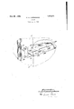
In the accompanying drawing, an anchor of dimensions substantially greater than the thickness of the mortar 21, as illustrated, and
lies the bolts 8 and 10 are positioned one on each side of the mortar, as shown. Two of these anchor bolts are, in practice, positioned one on each side of the window, and the terminals of the ropes from the window cleaners belt are adapted to be fastened to the bolts 8 and 10 of each anchor. The lower bolts 10 are adapted to sustain the window cleaner while at work, and the upper bolts are adapted to carry his weight in case he should slip 01' fall.
An anchor arm 12 projects from the bolt arm about half way between the bolts 8 and 10 substantially at right angles to the .bolt arm and comprises, in its preferred embodiment, a flat cross-shaped member one of the arms 14 of which is provided with an upstanding projection 16, and another arm 18 of which is provided with'an upstanding projection 20. The anchor arm is adapted to be placed in position in the. mortar 21 between the stones 2 and t before the stones have been laid in place, during the erection of the building. The projections 16 and 20, respectively, resists displacing forces longitudinally of the anchor arm and transversely thereto. Additional projections may be provided, if desired, and particularly upon the arm 22. It is found in practice, however, that the use of .too many projections has a tendency to weaken, rather than strengthen, the anchoring effect, because, as there is so thin a layer of mortar between the stones, a multiplication of projections decreases the quantity of mortar employed and therefore weakens the joint as a whole, For this same reason, it is preferred to have the anchor arm in cross shape rather than in the form of a single wide, flat member. In fact, the various arms of the cross-shaped anchor arm add stability to the anchoring effect by providing additional means for resisting the displacing forces that would be exerted upon the anchor in case the window not against the stones of the wall, and.
cleaner fell from the window sill. The stability is further increased by the bolt arm 6 lying fiat against the stones on each side of the mortar, as shown.
It will be obvious to persons skilled in the art that changes may readily be effected without departing from the spirit of the invention, a preferred embodiment of which has been illustrated and described. All such changes and modifications are desired to be included within the scope of the appended claims.
lVhat is claimed is:
1. An anchor comprising a bolt arm and an anchor arm, the anchor arm being of dimensions such that it is adapted to be embedded substantially horizontally in the mortar of a building wall, and the bolt arm being of dimensions substantially greater than the thickness of the mortar, whereby the bolt arm isadapted to engage against the building wall, and two bolts carried by the bolt arm, one of the bolts being adapted to be positioned above the mortar and the other bolt below the mortar.
2. An anchor comprising a bolt arm and a flat anchor arm disposed substantially at right angles to the bolt arm, the flat anchor arm being of dimensions such that itis adapted to be embedded substantially horizontally in the mortar of a building wall, the bolt arm being of dimensions substan tially greater than the thickness of the mortar and being adapted to be vertically dis posed in engagement with the building wall on both sides of the mortar, and two bolts carried by the bolt arm, one of the bolts being adapted to be positioned above the mortar and the other bolt below the mortar, the bolts being adapted to be disposed in substantially. vertical alignment.
An anchor comprising a bolt arm and an anchor arm disposed in planes substantially at right angles to each other, the anchor arm being of dimensions such that it is adapted to be embedded substantially horizontally in the mortor of a building wall, and the bolt arm being of dimensions substantially greater than the thicl-tness of the mortar, whereby the bolt arm is adapted to engage against the building wall, the anchor arm having an arm extending at an angle thereto, the last-named arm and the body portion of the anchor arm having each a projection adapted, respectively, to coact solely with the mortar to resist displacing forces at right angles to each other.
'4. An anchor comprising an anchor arm of dimensions such that it is adapted to be embedded in the mortar of a building wall and having two projections disposed at right angles to each other and adapted, re-
spectively, to solely coact with the mortar to resist displacing forces longitudinal of and transverse to the anchor arm.
5. An anchor comprising a bolt arm and an anchor arm, the anchor arm being of dimensions such that it is adapted to be embedded substantially horizontally in the mortar between the stones of a stone building wall and having means coacting with.
the mortar for resisting displacing forces longitudinal of and transverse to the anchor arm.
6. An anchor comprising a bolt arm and a flat anchor arm, the flat anchor arm being of dimensions such that it is adapted to be embedded substantially horizontally in the mortar between the stones of a stone build ing wall and having two projections disposed at right angles to each other and adapted, respectively, to coact solely with the mortar to resist displacing forces longitudinal of and transverse to the anchor arm.
7., An anchor comprising a bolt arm and an anchor arm, the anchor arm being of dimensions such that it is adapted to be embedded in the mortar of a building wall and having a terminal projection adapted to co act solely with the mortar to resist displacing forces in one direction and an intermediate projection adapted to coact solely with the mortar to resist displacing forces in a direction at right angles to the said one direction.
8. An anchor comprising a bolt arm and a cross-shaped anchor arm, the cross-shaped anchor arm being of dimensions such that it is adapted to be embedded substantially horizontally in the mortar between the stones of a stone building wall and two arms of the cross having each a projection adapted, respectively, to coact solely with the mortar to resist displacing forces longitudinal of and transverse to the anchor arm.
9. An anchor comprising a bolt arm and a flat, cross-shaped anchor arm disposed substantially at right angles to the bolt arm, the flat anchor arm being of dimensions such that it is adapted to be embedded substantially horizontally in the mortar between the stones of a stone building wall, with the bolt arm disposed substantially vertically, two of the arms of the cross having each a projection adapted, respectively, to coact solely with the mortar to resist displacing forces longitudinal of and transverse to the anchor arm.
In testimony whereof, I have hereunto subscribed my name this 8th day of January,
CHARLES A. CUNNINGHAM.
Priority Applications (1)
| Application Number | Priority Date | Filing Date | Title |
|---|---|---|---|
| US685208A US1574471A (en) | 1924-01-09 | 1924-01-09 | Anchor |
Applications Claiming Priority (1)
| Application Number | Priority Date | Filing Date | Title |
|---|---|---|---|
| US685208A US1574471A (en) | 1924-01-09 | 1924-01-09 | Anchor |
Publications (1)
| Publication Number | Publication Date |
|---|---|
| US1574471A true US1574471A (en) | 1926-02-23 |
Family
ID=24751185
Family Applications (1)
| Application Number | Title | Priority Date | Filing Date |
|---|---|---|---|
| US685208A Expired - Lifetime US1574471A (en) | 1924-01-09 | 1924-01-09 | Anchor |
Country Status (1)
| Country | Link |
|---|---|
| US (1) | US1574471A (en) |
-
1924
- 1924-01-09 US US685208A patent/US1574471A/en not_active Expired - Lifetime
Similar Documents
| Publication | Publication Date | Title |
|---|---|---|
| US3537220A (en) | Masonry wall brace | |
| US3471988A (en) | Anchoring device for tying wooden members to brick or masonry walls | |
| US3430397A (en) | Two-way wall brace | |
| US1946732A (en) | Veneer and backing bond and anchor | |
| US1574471A (en) | Anchor | |
| US2314927A (en) | Bead setter | |
| US984517A (en) | Outside wall. | |
| US3729882A (en) | Device for tying wooden members to composite brick and masonry walls | |
| US2131485A (en) | Sound deafening supporting means for floors | |
| US2174844A (en) | Adjustable anchor | |
| US1750841A (en) | Anchorage means | |
| US1816433A (en) | Anchor | |
| US689420A (en) | Hanger apparatus. | |
| US2008672A (en) | Building construction | |
| US2065796A (en) | Ceiling structure | |
| US1944787A (en) | Building construction | |
| US1393966A (en) | Concrete building structure | |
| US2015951A (en) | Anchoring device | |
| US1187918A (en) | Fastening device for plaster-board and the like. | |
| DE816305C (en) | Reinforced concrete ceiling beams | |
| US2211667A (en) | Joists and structural connections thereto | |
| US799988A (en) | Partition-wall construction. | |
| US540501A (en) | Tile-work | |
| US1787006A (en) | Putlog | |
| US1989504A (en) | Corner bead fastener |