US1574410A - Lubricating system for internal-combustion engines - Google Patents
Lubricating system for internal-combustion engines Download PDFInfo
- Publication number
- US1574410A US1574410A US506029A US50602921A US1574410A US 1574410 A US1574410 A US 1574410A US 506029 A US506029 A US 506029A US 50602921 A US50602921 A US 50602921A US 1574410 A US1574410 A US 1574410A
- Authority
- US
- United States
- Prior art keywords
- valve
- engine
- throttle
- oil
- lubricating system
- Prior art date
- Legal status (The legal status is an assumption and is not a legal conclusion. Google has not performed a legal analysis and makes no representation as to the accuracy of the status listed.)
- Expired - Lifetime
Links
Images
Classifications
-
- F—MECHANICAL ENGINEERING; LIGHTING; HEATING; WEAPONS; BLASTING
- F01—MACHINES OR ENGINES IN GENERAL; ENGINE PLANTS IN GENERAL; STEAM ENGINES
- F01M—LUBRICATING OF MACHINES OR ENGINES IN GENERAL; LUBRICATING INTERNAL COMBUSTION ENGINES; CRANKCASE VENTILATING
- F01M3/00—Lubrication specially adapted for engines with crankcase compression of fuel-air mixture or for other engines in which lubricant is contained in fuel, combustion air, or fuel-air mixture
- F01M3/02—Lubrication specially adapted for engines with crankcase compression of fuel-air mixture or for other engines in which lubricant is contained in fuel, combustion air, or fuel-air mixture with variable proportion of lubricant to fuel, lubricant to air, or lubricant to fuel-air-mixture
-
- F—MECHANICAL ENGINEERING; LIGHTING; HEATING; WEAPONS; BLASTING
- F02—COMBUSTION ENGINES; HOT-GAS OR COMBUSTION-PRODUCT ENGINE PLANTS
- F02B—INTERNAL-COMBUSTION PISTON ENGINES; COMBUSTION ENGINES IN GENERAL
- F02B75/00—Other engines
- F02B75/02—Engines characterised by their cycles, e.g. six-stroke
- F02B2075/022—Engines characterised by their cycles, e.g. six-stroke having less than six strokes per cycle
- F02B2075/025—Engines characterised by their cycles, e.g. six-stroke having less than six strokes per cycle two
Definitions
- gines and has for its object to provide a system of this character wherein the lubricant is supplied to the engine in proportion to the speed at which the engine is running thereby insuring a proper supply of lubricant at all times, the sup ly of lubricant being entirely shut ofl' w en the engine is stopped to preclude any possibility of an excess supply of oil and consequent waste.
- Another object is to provide a system of this character which is adapted to utilize the various grades of oil with equal efiiciency and which is in general of simple and durable construction, reliable in operation and easy and inexpensive to manufacture and install.
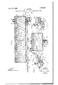
- Fi re 1 is a pers ective view, illustrating 1: e invention em odied in the internal combustion engine of an automobile;
- FIG 2 is a fragmentary view, showing a slightly modified form of the invention, only the carbureter of the internal combustion engine being shown
- Figure 3 is a detail view in longitudinal vertical section of the oil reservoir and associated valve mechanism
- Figure 4 is a view in transverse section on line 4-4 of Figure 3.
- the numeral 16 designates generally an internal corn bustion engine having a carbureter 11 provided with an outlet pipe 12 which is con nected with an inanifeld 13.
- the let pipe and the intake aid 13 can stitute the feel of the i . «l combus- Serial No. 506,029.
- a butter-fl or throttle valve [5 is operativel arrange in the pipe 12 and is provided wit a stem 16 which extends extcriorly of the pipe 12 and which is rigidly connected to the elbow "17 of a bell crank lever, designated generally at 18
- An arm 19 of the bell crank lever is ivotally secured to one end of a link 20, the other end of which is pivotally connected to a crank 21 fixed to the lower end of the controlling shaft which is actuated from the throttle control lever provided as usual on the steerin wheel.
- Ihe engine includes a crank case 25 having an opening26 constituting an oil inlet.
- An oil reservoir or tank 27 is arranged on the crank case and includes a removable filling cap 28.
- a valve block 30 depends from the oil reservoir and is fitted into the oil inlet 26.
- an oil passage 31 is provided which leads from the outlet of the oil reservoir to a valve cavity 32 also provided in the valve block and communicating with a second oil passage 33 which leads through the valve block from the valve cavity to the oil inlet to the crank case.
- a valve seat 34 is provided and a conical needle valve 35 coacts with this valve seat and 0perates in the valve cavity 32.
- the needle valve 35 regulates the flow of the lubricant from the reservoir to the engine.
- the needle valve 35 is provided with, an elongated valve stem 36 which slidably extends through a stuflin box 37 carried by the valve block and t rough a bearing 38 carried by the oil reservoir at a point remote from the valve block.
- a connecting rod 39 has one end pivotally secured to the free end of the valve stem 36 and has its other end pivotally secured to the arm 22 of the bell crank lever 18.
- the rod is connected with the openings at the extreme outer end of the arm so that a rela-- tively great throw is imparted to the needle valve whereby it is o ened to a maximum extent.
- the connecting rod is associated with openings adjacent the axis ofswing of the bell crank lever so that the needle valve is open only to a slight extent.
- a throttle associated with the fuel inlet and governing the supply of fuel flowing therethrough to the engine, operating means positively and directly connected to the throttle for controlling and adjusting the same throughout its range of movement means for supplying lubricant to the lubricating system of the engine and including an oil reservoir having a directly and downwardly extending connection projecting into the engine casing, a valve incorporated in said connection and operable to shut off or to permit in varying degrees the flow of lubricant from said oil reservoir to said engine under the influence of gravity, said valve being directly connectat to and controlled by the operating means for the throttle whereby to be shut oil when the throttle is shut oil and o ened as and when and in proportion to the degree to which the throttle is opened.
- valve lncorporated in said connection and adapted to shut off or to permit in varying degrees the flow of lubricant from said oil reservoir to said engine under the influence of gravity and motion transmission means between one of the arms. and the bell crank lever and said valve whereby when the throttle is opened the valve will be opened to a proportionate extent and when the throttle is closed the valves will beclosed.
Description
Feb. Z23 1926. 1,574,410
c. L. POWELL LUBRI CATING SYSTEM FOR INTERNAL COMBUSTION ENGINES Filed Oct. '7, 1921 I II II I II IIII I ll'I 'II IIIII I I *II II III I IIHI I I" w I I II'HII'I I I I'II Ii "III I IIIIII' IIH I I II ""IIII I II I |I|IIIII I I N WITNESSES I a;
4 TTORNEYS Patented Feb. 23, i 1926.
UNITED STATES GLAUDE I LACY POWELL, OF ALAMO, TENNESSEE.
LUBRICATING SYSTEM FOR INTERNAL-COMBUSTION ENGINES.
Application filed October 7, 1921.
To all whom it may concern:
' Be it known that I, CLAUDE LACY POWELL,
a citizen of the United States, and a resident.
gines, and has for its object to provide a system of this character wherein the lubricant is supplied to the engine in proportion to the speed at which the engine is running thereby insuring a proper supply of lubricant at all times, the sup ly of lubricant being entirely shut ofl' w en the engine is stopped to preclude any possibility of an excess supply of oil and consequent waste.
Another object is to provide a system of this character which is adapted to utilize the various grades of oil with equal efiiciency and which is in general of simple and durable construction, reliable in operation and easy and inexpensive to manufacture and install. I I
Other objects and advantages of the invention reside in certain novel features of construction, combination and arrangement of parts which will be hereinafter more fully described and particularly pointed out in the appended claims, reference being had to the accom anying drawings forming part of this spec' cation, and in which:
Fi re 1 is a pers ective view, illustrating 1: e invention em odied in the internal combustion engine of an automobile;
Figure 2 is a fragmentary view, showing a slightly modified form of the invention, only the carbureter of the internal combustion engine being shown Figure 3 is a detail view in longitudinal vertical section of the oil reservoir and associated valve mechanism; and
Figure 4 is a view in transverse section on line 4-4 of Figure 3.
' Referring to the drawings wherein for the sake of illustration is shown the preferred embodiment of the invention, the numeral 16 designates generally an internal corn bustion engine having a carbureter 11 provided with an outlet pipe 12 which is con nected with an inanifeld 13. The let pipe and the intake aid 13 can stitute the feel of the i .......l combus- Serial No. 506,029.
tion engine. A butter-fl or throttle valve [5 is operativel arrange in the pipe 12 and is provided wit a stem 16 which extends extcriorly of the pipe 12 and which is rigidly connected to the elbow "17 of a bell crank lever, designated generally at 18 An arm 19 of the bell crank lever is ivotally secured to one end of a link 20, the other end of which is pivotally connected to a crank 21 fixed to the lower end of the controlling shaft which is actuated from the throttle control lever provided as usual on the steerin wheel.
Ihe engine includes a crank case 25 having an opening26 constituting an oil inlet.
An oil reservoir or tank 27 is arranged on the crank case and includes a removable filling cap 28. A valve block 30 depends from the oil reservoir and is fitted into the oil inlet 26. In the valve block 30 an oil passage 31 is provided which leads from the outlet of the oil reservoir to a valve cavity 32 also provided in the valve block and communicating with a second oil passage 33 which leads through the valve block from the valve cavity to the oil inlet to the crank case. At the point where the passage 31 communicates with the valve cavity, a valve seat 34 is provided and a conical needle valve 35 coacts with this valve seat and 0perates in the valve cavity 32. The needle valve 35 regulates the flow of the lubricant from the reservoir to the engine. The needle valve 35 is provided with, an elongated valve stem 36 which slidably extends through a stuflin box 37 carried by the valve block and t rough a bearing 38 carried by the oil reservoir at a point remote from the valve block. A connecting rod 39 has one end pivotally secured to the free end of the valve stem 36 and has its other end pivotally secured to the arm 22 of the bell crank lever 18.
When the engine is running, the throttle valve is open to a greater or lesser degree, the bell crank 18 having been moved to open the throttle valve. This movement of the bell crank lever is transmitted to the needle valve to open the valve by means of an arm 22 connecting rod 39 and valve stem 36. It is obvious that the needle valve is thus constrained to partake of corresponding mo tion with the throttle valve so that as the throttle valve is opened, the needle valve is open and as the throttle valve is closedtlic needle valve is closed. From this it follows llll) ill) that when the engine is speeded up the supply of oil is increased since the needle valve is moved away from its seat and permits the How of lubricant through the oil passages of the valve block and on the other hand when the throttle valve is closed the needle valve is closed and entirely shuts oil the How of responds with the connecting rod 39. It is obvious that by securing the connecting rod with the openings 46 nearer to the center the throw im arted by the 'bell crank to the needle va ve will be decreased, When oils.
of relatively high viscosity are utilized the rod is connected with the openings at the extreme outer end of the arm so that a rela-- tively great throw is imparted to the needle valve whereby it is o ened to a maximum extent. On the other and when oils of relatively low viscosity are utilized the connecting rod is associated with openings adjacent the axis ofswing of the bell crank lever so that the needle valve is open only to a slight extent.
I claim:
1. In combination with an internal combustion engine having a lubricating system and also having a fuel inlet, a throttle associated with the fuel inlet and governing the supply of fuel flowing therethrough to the engine, operating means positively and directly connected to the throttle for controlling and adjusting the same throughout its range of movement means for supplying lubricant to the lubricating system of the engine and including an oil reservoir having a directly and downwardly extending connection projecting into the engine casing, a valve incorporated in said connection and operable to shut off or to permit in varying degrees the flow of lubricant from said oil reservoir to said engine under the influence of gravity, said valve being directly connectat to and controlled by the operating means for the throttle whereby to be shut oil when the throttle is shut oil and o ened as and when and in proportion to the degree to which the throttle is opened.
2. In combinationwith an internal combustion engine having a lubricating system and alsohaving a fuel inlet, a throttle asso-' ciated with the fuel inlet and governing the supply offuel flowing therethrough to the engine, said throttle having a stem about the axis of which it rotates, operating means positively controlling said throttle and in cluding a bell crank lever fastened to the stem'and having a pair of arms means for supplying lubricant to the lubricating system of the engine andincluding an oil res-.
ervoir having a directly and downwardly extending connection projecting into the engine casing, a valve lncorporated in said connection and adapted to shut off or to permit in varying degrees the flow of lubricant from said oil reservoir to said engine under the influence of gravity and motion transmission means between one of the arms. and the bell crank lever and said valve whereby when the throttle is opened the valve will be opened to a proportionate extent and when the throttle is closed the valves will beclosed.
CLAUDE LACY POWELL.
Priority Applications (1)
| Application Number | Priority Date | Filing Date | Title |
|---|---|---|---|
| US506029A US1574410A (en) | 1921-10-07 | 1921-10-07 | Lubricating system for internal-combustion engines |
Applications Claiming Priority (1)
| Application Number | Priority Date | Filing Date | Title |
|---|---|---|---|
| US506029A US1574410A (en) | 1921-10-07 | 1921-10-07 | Lubricating system for internal-combustion engines |
Publications (1)
| Publication Number | Publication Date |
|---|---|
| US1574410A true US1574410A (en) | 1926-02-23 |
Family
ID=24012861
Family Applications (1)
| Application Number | Title | Priority Date | Filing Date |
|---|---|---|---|
| US506029A Expired - Lifetime US1574410A (en) | 1921-10-07 | 1921-10-07 | Lubricating system for internal-combustion engines |
Country Status (1)
| Country | Link |
|---|---|
| US (1) | US1574410A (en) |
Cited By (2)
| Publication number | Priority date | Publication date | Assignee | Title |
|---|---|---|---|---|
| US2944538A (en) * | 1956-10-18 | 1960-07-12 | Magnaflux Corp | Lubrication system for chain saws |
| US4690249A (en) * | 1986-05-20 | 1987-09-01 | Olson Jr Theodore D | Precisely recurrently controllable dropwise liquid-feeders |
-
1921
- 1921-10-07 US US506029A patent/US1574410A/en not_active Expired - Lifetime
Cited By (2)
| Publication number | Priority date | Publication date | Assignee | Title |
|---|---|---|---|---|
| US2944538A (en) * | 1956-10-18 | 1960-07-12 | Magnaflux Corp | Lubrication system for chain saws |
| US4690249A (en) * | 1986-05-20 | 1987-09-01 | Olson Jr Theodore D | Precisely recurrently controllable dropwise liquid-feeders |
Similar Documents
| Publication | Publication Date | Title |
|---|---|---|
| US2595720A (en) | Carburetor | |
| US1574410A (en) | Lubricating system for internal-combustion engines | |
| US2128154A (en) | Internal combustion engine | |
| US1397780A (en) | Fuel-feeding system | |
| US2187998A (en) | Upper cylinder lubricator | |
| US1578216A (en) | Attachment for internal-combustion engines | |
| US1401081A (en) | Oil control and oil-feeder | |
| US1373550A (en) | Carbureter | |
| US2182580A (en) | Carburetor | |
| US1421583A (en) | Oiling device | |
| US1187761A (en) | Lubricating system for explosive-engines. | |
| US1450628A (en) | Carburetor | |
| US2115910A (en) | Air control device | |
| US2032822A (en) | Lubricating system for internal combustion engines | |
| US1627761A (en) | Internal-combustion engine | |
| US1769133A (en) | Thermostatic regulator for internal-combustion engines | |
| US1582253A (en) | Lubricating system | |
| US2155560A (en) | Carburetor | |
| US1024862A (en) | Internal-combustion engine. | |
| US1749721A (en) | Carburetor | |
| US1188061A (en) | Device for the automatic control of engines. | |
| US1835299A (en) | Supercharging apparatus for internal combustion engines | |
| US1337226A (en) | Priming device | |
| US1604221A (en) | Carburetor air control | |
| US1210533A (en) | Carburation device for internal-combustion engines. |