US1551902A - Sheet-metal cabinet - Google Patents
Sheet-metal cabinet Download PDFInfo
- Publication number
- US1551902A US1551902A US678876A US67887623A US1551902A US 1551902 A US1551902 A US 1551902A US 678876 A US678876 A US 678876A US 67887623 A US67887623 A US 67887623A US 1551902 A US1551902 A US 1551902A
- Authority
- US
- United States
- Prior art keywords
- wall
- cabinet
- secured
- side walls
- walls
- Prior art date
- Legal status (The legal status is an assumption and is not a legal conclusion. Google has not performed a legal analysis and makes no representation as to the accuracy of the status listed.)
- Expired - Lifetime
Links
- 239000002184 metal Substances 0.000 title description 18
- 238000005452 bending Methods 0.000 description 5
- 239000000463 material Substances 0.000 description 3
- 238000005192 partition Methods 0.000 description 3
- 239000007787 solid Substances 0.000 description 3
- 229910000831 Steel Inorganic materials 0.000 description 2
- 229960001948 caffeine Drugs 0.000 description 2
- 239000011810 insulating material Substances 0.000 description 2
- 239000010959 steel Substances 0.000 description 2
- RYYVLZVUVIJVGH-UHFFFAOYSA-N trimethylxanthine Natural products CN1C(=O)N(C)C(=O)C2=C1N=CN2C RYYVLZVUVIJVGH-UHFFFAOYSA-N 0.000 description 2
- 101100379079 Emericella variicolor andA gene Proteins 0.000 description 1
- 241000733322 Platea Species 0.000 description 1
- 238000010276 construction Methods 0.000 description 1
- VKYKSIONXSXAKP-UHFFFAOYSA-N hexamethylenetetramine Chemical compound C1N(C2)CN3CN1CN2C3 VKYKSIONXSXAKP-UHFFFAOYSA-N 0.000 description 1
- 238000004519 manufacturing process Methods 0.000 description 1
- 239000000126 substance Substances 0.000 description 1
Images


Classifications
-
- E—FIXED CONSTRUCTIONS
- E05—LOCKS; KEYS; WINDOW OR DOOR FITTINGS; SAFES
- E05G—SAFES OR STRONG-ROOMS FOR VALUABLES; BANK PROTECTION DEVICES; SAFETY TRANSACTION PARTITIONS
- E05G1/00—Safes or strong-rooms for valuables
- E05G1/005—Portable strong boxes, e.g. which may be fixed to a wall or the like
-
- E—FIXED CONSTRUCTIONS
- E05—LOCKS; KEYS; WINDOW OR DOOR FITTINGS; SAFES
- E05G—SAFES OR STRONG-ROOMS FOR VALUABLES; BANK PROTECTION DEVICES; SAFETY TRANSACTION PARTITIONS
- E05G1/00—Safes or strong-rooms for valuables
- E05G1/02—Details
- E05G1/024—Wall or panel structure
-
- E—FIXED CONSTRUCTIONS
- E05—LOCKS; KEYS; WINDOW OR DOOR FITTINGS; SAFES
- E05G—SAFES OR STRONG-ROOMS FOR VALUABLES; BANK PROTECTION DEVICES; SAFETY TRANSACTION PARTITIONS
- E05G1/00—Safes or strong-rooms for valuables
- E05G1/02—Details
- E05G1/026—Closures
-
- E—FIXED CONSTRUCTIONS
- E05—LOCKS; KEYS; WINDOW OR DOOR FITTINGS; SAFES
- E05G—SAFES OR STRONG-ROOMS FOR VALUABLES; BANK PROTECTION DEVICES; SAFETY TRANSACTION PARTITIONS
- E05G1/00—Safes or strong-rooms for valuables
- E05G1/02—Details
- E05G1/04—Closure fasteners
-
- E—FIXED CONSTRUCTIONS
- E05—LOCKS; KEYS; WINDOW OR DOOR FITTINGS; SAFES
- E05G—SAFES OR STRONG-ROOMS FOR VALUABLES; BANK PROTECTION DEVICES; SAFETY TRANSACTION PARTITIONS
- E05G2700/00—Safes or accessories thereof
Definitions
- This invention relates to cabinets, de
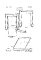
- Fig. 1 is a front elevation, with the ⁇ door of the cabinet partly broken away;
- l Fig. 2 is a section on line 2-2, Fig. 1;
- Fig. 3 is a section on line 3-3, Fig. 2, looking toward the left;
- Figs. 4 and 5 are sections on the liner 4 4, Fig. l, Fig. 4 showing only the outer wall of what I term the body part of the cabinet and Fig. 5 showing all the parts revealed by the section, the door being open and a certain drawer partly withdrawn;
- Fig. 6 shows in underneath perspective the cover or top
- Fig'? is a section on line 7 7, Fig. 6.
- the body part of the cabinet is formed hollow and outwardly seamless by two spaced wall structures, inner and outer,A each preferably consisting off a single piece of sheet metal, as steel.
- The. outer wall structure (Fig. 4) is formed from an elongated blank, which would be substantially rectangular in plan,
- bendmg the extreme edges of the material topearance may if desired be imparted to thev back b and two side walls c of' the structure by bending the blank, as at b o', also on [lines perpendicular to its long sides in a manner to leave more or less vof the middle portion of each such wall set in relatively to the lateral margins thereof.
- the inner wall structure is also formed from lan elongated blank, substantially rectangular in plan, by bending off in the same direction the end portions of the blank so that said end portions stand parallel with each other, thus producing the back wall h and the two side walls i i, and then bending the extreme edges of the end portions referably toward each other and so as to ie in the same plane, producing Hanges 7' y', all the lines of being perpendicular to the long sides of the blank.
- the inner wall structure is assembled with the outer wall structure by placing it therein, as shown best by dotted lines in Fig. 4, so that the flanges 7' of the former abut face to face and rearwardly against the flanges f, whereupon these flanges are secured together from top to bottom' in some substantial and permanent manner, as'by rivets, to form a com vosite flange or joint f-j.
- the hol1owwal ed structure dthus produced generally U-shaped in plan, has great strength for its tangular as stated, may have extensions projecting from' what is to .be its lower edge in. the finished 'outer wall structure, arranged preferably so that the lines of bending' to produce the walls 6,. c and d willbisect them; these extensions will then form legs Z, reinforced by being angular in crosssection.
- a bottom for the cabinet is formed as follows: A horizontal plate or wall m, preferably of heavier' ⁇ material than that used for the aforesaid wall structures and having in plan the same Igeneral contour as the interior of the spaced form by walls b, c, d, e, of the outer wall structure (being cutaway at the front between the two-front columns, as at m', Fig. 5-see also Fig.
- a falseV bottom consisting of'a' horizontal rectangular plate p, having the same form and dimensions as ,the interior of the inner j wall structure and having depending fianges greater areathan theouter wall structure is .arranged upon -and permanently secured thereto, and preferably also to the innerwall structure, as -by the walls of these structures having angular projections, as flanges s s,
- a cap a' surmounts the cabinet and 1s permaf nently secured to flanged plate 7" as follows.
- This cap u has a vdepending continuous fiange u which at each of its foursides and at the lower edge thereof is provided with an inturned lip u which in plan (seeFig.
- a closure for the front opening of the cabinet is formed by two rectangular plates /v w having their margins v fw bent off all around, one of these thus shallow rectangular members being tted into the other with the open side of each facing the other.
- Two' heavy strips (Figs. 4 and 5) may be welded or otherwise secured to the inner surfaces -of thewalls e to chan'en them in the plane ofthe door when in closed position and also afford a more solid support for the door or closurewhere it ishinged, at y, and
- the *drawer 5 is arranged to slide in grooved guides 6, each formed 'of a piece of channeled sheet metal, which have frontal fianges 6*. secured by the rivets lc tothe joints or flanges f-"and tangs 6b passed thron h holes in sai wall la,r and bent over.
- the le comprises a frontwall 7 of sheet metal, a bottom wall 8 secured thereto and.
- the outermost partitions 9 are spaced apart a disis tiltedforwardand su lport it in that position; by pressing lsai partitions (which are sufficiently fiexible forthe purpose) toward each other the lu I will clear the joints or fianges, permittng. the file tol be removed bodily from the cabinet.
- the available v spaces existing in the exterior wall structure of the improved cabinet may be filled with any fire-insulating material, as'air or some solid substance;
- an advantage of the described construction of the body part of the cabinet is that if it is desired that the insulating material be in the form of solid lmaterial it may be molded into slabs and the slabs introduced into the spaces between the inner and outer wall structures after the latter are assembled.
- a cabinet including, in combination, two one-piece upright sheet-metal wall structures one of which is contained in the other and each of which includes a back wall and two side walls, the back wall and side walls of one struct-ure being spaced from the back wall and side walls, respec tively, of the other /structure and the outer structure having portions forming forward integral continuations of its side walls rebent inwardly and secured to the forward portions of the side walls of the inner structure, whereby .an outwardly seamless .body part is formed having a front opening, a' bottom and a top for the cabinet each secured to one of said structures, and a closure for said front opening.
- a cabinet including, in combination,
- a cabinet including, in combination, two one-piece upright sheet-metal wall structures one of which is contained in the other and each of which includes a back wal] and two side walls, the back wall and side walls of one struct-ure being spaced' from the back wall and side walls, respectively, of the other structure and the inner structurehaving the forward edges of its side walls bent oft' and the outer structure Vhaving portions forming forward continuations of its side walls rebent inwardly and theeXtreme edges of said continuations bent off and secured to and thereby forming a joint with said bent-off edges'of the side walls of the inner structure, whereby an outwardly seamless body part is formed having a front opening, bracing means connecting the back wall of the inner structure with each of said joints, a bottom and atop for the cabinet each secured to one of said structures, and a closure ⁇ for said front opening.
- a cabinet including, in combination, twoupright sheet-metal wall structures one of which is contained in the other and each of which includes a back and two side walls, the'back -walls being spacedfrom each other and' the two corresponding side walls of said structures being spaced from each other forward ⁇ from said back walls but joined together at their forward portions, whereby a hollow structure generally U-shaped in plan is formed having an opening between the forward portions of the side walls of the inner structure, .said walls having projections extending from their upper and lower edges in angular relation thereto, a bottom and a top respectively secured to the lower and the upper projections, and a closure for the opening.
- a cabinet including, in combination, a body part having a polygonal to flange -projecting laterally all around, an n a sheet metal cap including a polygonal horizontal wall substantially conforming in plan to the plan of said flange, flanges dependin from the several sides of said wall, and lnward flips extending along the flanges and each having its greatest width between its ends and being gradually reduced in width toward both ends thereof, said cap belng sprung over said flange of the body part and having its lips engaged under said top fiange.
- a top Atherefor comprising a sheet metal lhorizontal wall formed polygonal in plan and adapted to be secured on the body part and having marginal upstanding. flanges, and a sheet metal cap including a polygonal horizontal wallsubs'tantially conforming in plan to the plan of the first wall,
- capwall depending from the several sides of the capwall, and inward lips extending l'oo along the latter anges and each having its greatest width between its ends and being gradually reduced in width toward bothy ends thereof, said cap being sprung overy said first wall and having its llps engaged marginally thereunder.
Landscapes
- Assembled Shelves (AREA)
Description
Sept 1,1925. 1 1,551,902I
CA.NELSON `sHEET METAL CABINET Septy 1, 1925.
` c. A. NELSON SHEET METAL CABINET Filed Deo. 6, 1925 4 Sheets-Sheet 2 "ATTORNEY Sept. 1
C. A. NELSON SHEET METAL CABINET Fled Dec. 6. 1923 4 Shees-Sheet 5 WITNESS Sept 1, 1925.
C. A.'NELSON SHEET METAL CABINET 4 Sheets-Sheet 4 Filed Deo WITNESS A TTOR/VE Y Patented Sept. 1,. 1925.
1,551,902 ,UNITI-:D STATES' PATENToFFlcE.
CHARLES A. NELSON, OF WATERTOWN, NEW YORK, ASSIGNOR F FORTY-NINE ONE- HUNDREDTHS TO FREDERICK D. G. HARTMANN, O'F UTICA, NEW YORK- SHEET-METAL CABINET.
Application led December 6', 1923.4 Serial No. 678,876.
To all whom tmay concern:
Be it known that I, CHARLES A.l NELsoN, a citizen of the United States, residing at Watertown, in the county of J ederson and State of New York, have invented certain new and. useful Improvements in Sheet- Metal Cabinets, of which the following is a specification,
This invention relates to cabinets, de
as steel, and yet be inexpensive to manufacture and attractive in appearance and comparatively light in weight, Whilehaving great strength so as both to resist attempts to obtain access to its contents by force andA the wear and tear incident .to moving it about, and also the ability to resist any fire of at least a merely local character.
In the drawings,
Fig. 1 is a front elevation, with the` door of the cabinet partly broken away; l Fig. 2 is a section on line 2-2, Fig. 1; Fig. 3 is a section on line 3-3, Fig. 2, looking toward the left;
Figs. 4 and 5 are sections on the liner 4 4, Fig. l, Fig. 4 showing only the outer wall of what I term the body part of the cabinet and Fig. 5 showing all the parts revealed by the section, the door being open and a certain drawer partly withdrawn;
Fig. 6 shows in underneath perspective the cover or top; and
Fig'? is a section on line 7 7, Fig. 6. The body part of the cabinet is formed hollow and outwardly seamless by two spaced wall structures, inner and outer,A each preferably consisting off a single piece of sheet metal, as steel.
The. outer wall structure (Fig. 4) is formed from an elongated blank, which would be substantially rectangular in plan,
^ by bending ofi' in the aame direction the end portions of the blank so that said'end portions stand parallel with each other, thus producing the back lwall b and the two side walls c c, then rebending inwardly the material forming continuations of the walls c c on parallel lines, so that there result narrow front walls d d and rearwardly projecting interior narrow walls e e, and. finally bendmg the extreme edges of the material topearance may if desired be imparted to thev back b and two side walls c of' the structure by bending the blank, as at b o', also on [lines perpendicular to its long sides in a manner to leave more or less vof the middle portion of each such wall set in relatively to the lateral margins thereof.
The inner wall structure is also formed from lan elongated blank, substantially rectangular in plan, by bending off in the same direction the end portions of the blank so that said end portions stand parallel with each other, thus producing the back wall h and the two side walls i i, and then bending the extreme edges of the end portions referably toward each other and so as to ie in the same plane, producing Hanges 7' y', all the lines of being perpendicular to the long sides of the blank.
The inner wall structure is assembled with the outer wall structure by placing it therein, as shown best by dotted lines in Fig. 4, so that the flanges 7' of the former abut face to face and rearwardly against the flanges f, whereupon these flanges are secured together from top to bottom' in some substantial and permanent manner, as'by rivets, to form a com vosite flange or joint f-j. The hol1owwal ed structure dthus produced, generally U-shaped in plan, has great strength for its tangular as stated, may have extensions projecting from' what is to .be its lower edge in. the finished 'outer wall structure, arranged preferably so that the lines of bending' to produce the walls 6,. c and d willbisect them; these extensions will then form legs Z, reinforced by being angular in crosssection. t
A bottom for the cabinet is formed as follows: A horizontal plate or wall m, preferably of heavier'` material than that used for the aforesaid wall structures and having in plan the same Igeneral contour as the interior of the spaced form by walls b, c, d, e, of the outer wall structure (being cutaway at the front between the two-front columns, as at m', Fig. 5-see also Fig. 2), is secured in some permanent manner to the lower edge portions of said walls b c d e, as by said walls having angular projections, here shown as flanges n', on whichthe plate m marginally rests and to which it is secured, as by- `rivets 0'; at least the side walls i of thein# ner wall structure h z' ma have angular pro- ..jections, as fianges n, Fig. 3) secured, as
- by rivets o", to this plate, thus at the bottom to hold the inner wallstructure rigidly in parallel relation to the outer wall structure. A falseV bottom, consisting of'a' horizontal rectangular plate p, having the same form and dimensions as ,the interior of the inner j wall structure and having depending fianges greater areathan theouter wall structure is .arranged upon -and permanently secured thereto, and preferably also to the innerwall structure, as -by the walls of these structures having angular projections, as flanges s s,
t0 which said late r 1s secured, as by rivets t. plate r has preferably a marginal upstanding fiange 1". all around. On4 account of its superior area it affords an ex- ,terior top ange or crown on the cabinet. A cap a' surmounts the cabinet and 1s permaf nently secured to flanged plate 7" as follows. This cap u has a vdepending continuous fiange u which at each of its foursides and at the lower edge thereof is provided with an inturned lip u which in plan (seeFig. 6) is graduated in width from the middle of the lip, where it is widest, toward each end thereof, where it disappears, so thatat each corner of the (angular) flange u the lipformation does not exist. This cap u is applied to the flanged plate r of the cabinet by placing it thereon, open side downward,
then engaging the lips uff-thereof .corresponding to two adjoining sides of its flange under saidA top flange, and finally, having sprun or bowed outwardly the other two adjoining sides of its flange so that thein' lips will clear the top fiange, forcing the plate downward until the .latter lips lock under Once the platea has thus said top'flange. been applied 1t becomes a permanent part of the cabinet and cannot be removed, due to its inherent stiffness, without the application of special means.
A closure for the front opening of the cabinet is formed by two rectangular plates /v w having their margins v fw bent off all around, one of these thus shallow rectangular members being tted into the other with the open side of each facing the other. Two' heavy strips (Figs. 4 and 5) may be welded or otherwise secured to the inner surfaces -of thewalls e to stift'en them in the plane ofthe door when in closed position and also afford a more solid support for the door or closurewhere it ishinged, at y, and
for the engagement of the -bolt of the locking means z, which' is here shown as including a knob e apertured to receive a' key.
It is not materialliow the interior of the cabinet vis avai/led of. I however show it as containing a strongbox, a drawer or till rand a file for`papers, account books, etc. This stron -box, the 'guides or waysl in whichthe rawer moves and .the'false bottom p serve as means to brace the Astructure from` front to rearby/connecting the joints f-j with the back wall h.' The strong-box 3 has the lateral portions of its'front maru ginal .flange 3* secured by the rivets 7c to the jointor flange f-j, while its rear mari ginal flange 3h is secured by rivets 4 to' the back wall h. of the inner wall structure. 'The *drawer 5 is arranged to slide in grooved guides 6, each formed 'of a piece of channeled sheet metal, which have frontal fianges 6*. secured by the rivets lc tothe joints or flanges f-"and tangs 6b passed thron h holes in sai wall la,r and bent over. The le comprises a frontwall 7 of sheet metal, a bottom wall 8 secured thereto and.
projecting `rearwardly therefrom and upright sheet-metal partitions 9forming between them the filing spaces "and suitably secured to the walls 7 8. The lower edge of the wall 7 is bent forward to form a hinging flange 7", the said wall being adapted to bear against the joints or flanges f-j, depending below the top surface of the false bottom p, and secured vbl rivets l() to the front vdepending fiange of said false bottom are a hook or hoo s A11\;.which engage the flange "l"L and form therewith a vhinge whose members may only be separated when -the file is tilted forward sufficiently to permit the flangeto clear the hooks. The outermost partitions 9 are spaced apart a disis tiltedforwardand su lport it in that position; by pressing lsai partitions (which are sufficiently fiexible forthe purpose) toward each other the lu I will clear the joints or fianges, permittng. the file tol be removed bodily from the cabinet.
It will be understood that the available v spaces existing in the exterior wall structure of the improved cabinet, as between its inner and outer walls h, i, z' and I), 0, 0, between its'bottom-forming walls m and p, between its top-forming walls 7' u and between the members 'o' w of its door, may be filled with any fire-insulating material, as'air or some solid substance; an advantage of the described construction of the body part of the cabinet is that if it is desired that the insulating material be in the form of solid lmaterial it may be molded into slabs and the slabs introduced into the spaces between the inner and outer wall structures after the latter are assembled. l
Having thus fully described my invention, what I claim as new and desire to secure by Letters Patent is 1. A cabinet including, in combination, two one-piece upright sheet-metal wall structures one of which is contained in the other and each of which includes a back wall and two side walls, the back wall and side walls of one struct-ure being spaced from the back wall and side walls, respec tively, of the other /structure and the outer structure having portions forming forward integral continuations of its side walls rebent inwardly and secured to the forward portions of the side walls of the inner structure, whereby .an outwardly seamless .body part is formed having a front opening, a' bottom and a top for the cabinet each secured to one of said structures, and a closure for said front opening.
2. A cabinet including, in combination,
two one-piece upright sheet-metal wall structures one of which is contained in the other and each of which includes a back wall and two side walls, the back wall and 4side walls of one structure being spaced from the back wall and side wall, respectively, of the other structure and the inner structure having the forward edges of its side walls .bent oft and the outer structure having port-ions forming forward continuations of its side walls rebent inwardly and the extreme edges of said continuations bent oil1 and secured to and thereby formin a joint with said bent-oft' edges of the side walls of the inner structure, whereby an outwardly seamless body part is formed having a front opening, a bottom and a to for the cabinet each secured to one of sai structures, and a closure for said front opening.
3. A cabinet including, in combination, two one-piece upright sheet-metal wall structures one of which is contained in the other and each of which includes a back wal] and two side walls, the back wall and side walls of one struct-ure being spaced' from the back wall and side walls, respectively, of the other structure and the inner structurehaving the forward edges of its side walls bent oft' and the outer structure Vhaving portions forming forward continuations of its side walls rebent inwardly and theeXtreme edges of said continuations bent off and secured to and thereby forming a joint with said bent-off edges'of the side walls of the inner structure, whereby an outwardly seamless body part is formed having a front opening, bracing means connecting the back wall of the inner structure with each of said joints, a bottom and atop for the cabinet each secured to one of said structures, and a closure `for said front opening. y
4. A cabinet including, in combination, twoupright sheet-metal wall structures one of which is contained in the other and each of which includes a back and two side walls, the'back -walls being spacedfrom each other and' the two corresponding side walls of said structures being spaced from each other forward` from said back walls but joined together at their forward portions, whereby a hollow structure generally U-shaped in plan is formed having an opening between the forward portions of the side walls of the inner structure, .said walls having projections extending from their upper and lower edges in angular relation thereto, a bottom and a top respectively secured to the lower and the upper projections, and a closure for the opening. y
v5. A cabinet including, in combination, a body part having a polygonal to flange -projecting laterally all around, an n a sheet metal cap including a polygonal horizontal wall substantially conforming in plan to the plan of said flange, flanges dependin from the several sides of said wall, and lnward flips extending along the flanges and each having its greatest width between its ends and being gradually reduced in width toward both ends thereof, said cap belng sprung over said flange of the body part and having its lips engaged under said top fiange. l
6; In combination, with a cabinet body part, a top Atherefor comprising a sheet metal lhorizontal wall formed polygonal in plan and adapted to be secured on the body part and having marginal upstanding. flanges, and a sheet metal cap including a polygonal horizontal wallsubs'tantially conforming in plan to the plan of the first wall,
flanges depending from the several sides of the capwall, and inward lips extending l'oo along the latter anges and each having its greatest width between its ends and being gradually reduced in width toward bothy ends thereof, said cap being sprung overy said first wall and having its llps engaged marginally thereunder.
In testimony whereof I aflix my signature.
CHARLES NELSON.
Priority Applications (1)
| Application Number | Priority Date | Filing Date | Title |
|---|---|---|---|
| US678876A US1551902A (en) | 1923-12-06 | 1923-12-06 | Sheet-metal cabinet |
Applications Claiming Priority (1)
| Application Number | Priority Date | Filing Date | Title |
|---|---|---|---|
| US678876A US1551902A (en) | 1923-12-06 | 1923-12-06 | Sheet-metal cabinet |
Publications (1)
| Publication Number | Publication Date |
|---|---|
| US1551902A true US1551902A (en) | 1925-09-01 |
Family
ID=24724656
Family Applications (1)
| Application Number | Title | Priority Date | Filing Date |
|---|---|---|---|
| US678876A Expired - Lifetime US1551902A (en) | 1923-12-06 | 1923-12-06 | Sheet-metal cabinet |
Country Status (1)
| Country | Link |
|---|---|
| US (1) | US1551902A (en) |
Cited By (3)
| Publication number | Priority date | Publication date | Assignee | Title |
|---|---|---|---|---|
| US2679444A (en) * | 1950-08-07 | 1954-05-25 | Bennett Edgar Lloyd | Newsstand cabinet |
| US20070109068A1 (en) * | 2005-11-15 | 2007-05-17 | Gilbarco Inc. | Multi-layer security system and method to prevent unauthorized access to fuel dispenser compartments |
| US20190178021A1 (en) * | 2017-12-11 | 2019-06-13 | Nick Kohli | Use of Motion to Disguise a Locking Cabinet / Safe |
-
1923
- 1923-12-06 US US678876A patent/US1551902A/en not_active Expired - Lifetime
Cited By (3)
| Publication number | Priority date | Publication date | Assignee | Title |
|---|---|---|---|---|
| US2679444A (en) * | 1950-08-07 | 1954-05-25 | Bennett Edgar Lloyd | Newsstand cabinet |
| US20070109068A1 (en) * | 2005-11-15 | 2007-05-17 | Gilbarco Inc. | Multi-layer security system and method to prevent unauthorized access to fuel dispenser compartments |
| US20190178021A1 (en) * | 2017-12-11 | 2019-06-13 | Nick Kohli | Use of Motion to Disguise a Locking Cabinet / Safe |
Similar Documents
| Publication | Publication Date | Title |
|---|---|---|
| US3252614A (en) | Stackable pan | |
| US2458233A (en) | Metal suitcase | |
| US4062302A (en) | Shelving assembly with removable divider inserts | |
| US1551902A (en) | Sheet-metal cabinet | |
| US2164855A (en) | Mail box | |
| US1574314A (en) | Receptacle | |
| US2216277A (en) | Box | |
| US809497A (en) | Fire-resisting cabinet. | |
| US1967257A (en) | Stove construction | |
| US1869807A (en) | Wall cabinet | |
| US1916752A (en) | Insulated cabinet or receptacle | |
| US1833882A (en) | File cabinet | |
| US2239562A (en) | Fireplace screen | |
| US1294838A (en) | Fire-resisting cabinet. | |
| US1207066A (en) | File-container. | |
| US1485360A (en) | Metallic structure | |
| US2481877A (en) | Hinge | |
| US1720158A (en) | Baggage carrier | |
| US1392998A (en) | Metal desk | |
| US1876192A (en) | Insulated file cabinet | |
| US1567355A (en) | Safe-door structure | |
| USRE18670E (en) | Baggage carrier | |
| US969620A (en) | Automobile tool-box. | |
| US1947955A (en) | Collapsible wardrobe | |
| US1068676A (en) | Cabinet. |