US1551663A - Punch and guide therefor - Google Patents
Punch and guide therefor Download PDFInfo
- Publication number
- US1551663A US1551663A US729628A US72962824A US1551663A US 1551663 A US1551663 A US 1551663A US 729628 A US729628 A US 729628A US 72962824 A US72962824 A US 72962824A US 1551663 A US1551663 A US 1551663A
- Authority
- US
- United States
- Prior art keywords
- punch
- jaws
- guide
- work
- arms
- Prior art date
- Legal status (The legal status is an assumption and is not a legal conclusion. Google has not performed a legal analysis and makes no representation as to the accuracy of the status listed.)
- Expired - Lifetime
Links
- 238000004080 punching Methods 0.000 description 10
- 238000010276 construction Methods 0.000 description 5
- 229910000831 Steel Inorganic materials 0.000 description 4
- 239000010959 steel Substances 0.000 description 4
- 239000002184 metal Substances 0.000 description 2
- 238000012986 modification Methods 0.000 description 2
- 230000004048 modification Effects 0.000 description 2
- 244000228957 Ferula foetida Species 0.000 description 1
- 229910000760 Hardened steel Inorganic materials 0.000 description 1
- 238000005336 cracking Methods 0.000 description 1
- 210000005069 ears Anatomy 0.000 description 1
- 239000011521 glass Substances 0.000 description 1
- 230000000630 rising effect Effects 0.000 description 1
- 239000011435 rock Substances 0.000 description 1
Images
Classifications
-
- B—PERFORMING OPERATIONS; TRANSPORTING
- B21—MECHANICAL METAL-WORKING WITHOUT ESSENTIALLY REMOVING MATERIAL; PUNCHING METAL
- B21D—WORKING OR PROCESSING OF SHEET METAL OR METAL TUBES, RODS OR PROFILES WITHOUT ESSENTIALLY REMOVING MATERIAL; PUNCHING METAL
- B21D28/00—Shaping by press-cutting; Perforating
- B21D28/24—Perforating, i.e. punching holes
Definitions
- metal strips such as the orwardly-projectribs of'steel windo a sashes, and in general consists of a slotted guide provided with means for attaching the same toxthe work, and a 'togglejoint punch which is adapted toChave. its jaws inserted inthe' guide, after the latter has beenattached to the work, and then to be operated by means of a hand-wheel to punch the hole'in said work, both said guide and punch. beingof,
- the primary object of my invention is to provide what may be termed a set of implemen for expeditiously and economically punching holes by" hand "in strips of metal, the same being especially adapted for punching holes in the forwardly-pr'ojecting parts or ribs of steel window sashes in order,
- brackets for shades may be readily fastened to such sashes.
- This punch and guide are strong and durable, comparatively simple both in construction and ope-ration convenient to use, and
- Another object is to produce a punch of the guide which can be easily and quickly attached to and detached from the Work, and
- a furtherobject is tojinsure accuracy in perforatingthe holes, not only as to the distance apart of the holes hut als q as to their distance in from the front edgeof the work.
- Still another object is to: produce a punch
- Figure 1 1s a central, longitudinal section through a guide which: embodies a practical form of that elementv of my invention, looking down Fig. 2, a front elevation of; said guide; Fig.1 3,, a top. plan of a punch which embodies a practical form of: that element of said invention; Fig, ban elevation of the jaw end of said punch, the han dayheel being omitted, and a portion of the'handle being broken off; Fig. a central, longitudinalseotion through said punch, looking down, said hand-wheel being again omitted,
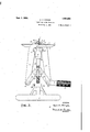
- the guide comprises a, plate which has on the front" side adjacent to'the longitudinal" edges thereof fl ge 3:3 and inte mediate, L tangular block or boss aprovided with forwardly-extending ears or lugs 55; that said plate has therein upper and under slots 6, and an intermediate slot 7 which extends clear through said plate from front to back; and that in the back side of the plate is a groove 8.
- the slot 7 is in the longitudinal center of the plate 2 and parallel with the slots 6, and extends through the boss 4.
- the inner faces of the lugs 5 are flush with the upper and under, longitudinal sides of the slot 7.
- the under side of the upper flange 3 and the upper side of the boss 4 are flush with the longitudinal sides of the upper slot 6, and the upper side of the lower flange 3 and the under side of said boss are flush with the longitudinal sides of the lower slot 6.
- the groove 8 is in the transverse center of the back side of the plate 2, at right-angles to the slots 6 and 7, and its continuit is interrupted by said slots.
- the front edge portion of the rib 1 is received in the groove 8.
- the pivots 11 are on opposite sides of and equidistant from the transverse, vertical plane in which the groove 8 is located.
- the arms 9 and 10 project through the slot 7 behind the plate 2, and the gripping posts 12 are set in adjacent sides of and project from said arms in position to en gage the rib 1.
- the arms 9 and 10 also project forwardly beyond the lugs 5, and the front end of the arm 9 is bifurcated at 17 to receive a part 18 of the screw 13. which part is unthreaded and of less diameter than the threaded portion of said screw.
- the collar 14 is secured to the outer end of the part 18 outside of the bifurcated terminal 17 while the washer 15 is mounted on said part inside of said terminal.
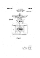
- This punch comprises a head 19, an externally screw-threaded spindle 20, an internally screw-threaded sleeve 21 mounted on the screw-threaded part of said spindle, two arms 22 pivotally connected adjacent to ther rear ends, at 2323, with said head, two pairs of links 24 each having one terminal pivotally connected at 25 with said sleeve and the other terminal pivotally connected at 26 with one of said arms at the forward end thereof, a punch pin 27, a stop 28, and a punch bushing 29.
- the links 24 in each pair are on opposite sides of said sleeve 21 and the arms 22.
- the head 19 has a slot 30 therein which opens through opposite sides and the rear end of said head, and inner projecting parts on the adjacent edges of the arms 22 are received in said slot and connected with said head by the pivots 23.
- an extension 31 At the rear end of the spindle 20 is an extension 31, and said spindle has thereon forward of such extension a flange 49.
- the extension 31 passes through a horizontal opening in the center of the head 19, and on the rear terminal of said extension, within the slot 30, is a washer 32 and a nut 33.
- the part of the head 19 through which the extension 31 passes is between the flange 49 and the aforesaid washer and nut. and the construction and arrange ment of parts are such that said extension can rotate freely but can not move independentlv endwise in said head.
- the nut 33 is pinned at 34 to the extension 31.
- the forward terminal, of the spindle 20 is slabbed off. as represented at 35 in Fig. 5. to form an angular or stem part for the reception of the hub 36 of a hand-wheel 37. a set-nut 38 being provided to prevent said hub from being withdrawn from said stem.
- a post 39 Extending outwardly from the rear terminal of one of the arms 22 is a post 39. and mounted on this post is a handle 40.
- the outer terminal of the post 39 is screwthreaded to receive a nut 41, by means of which the handle 40 is secured in place on said post. said nut being in said handle which is made hollow to receive it.
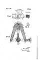
- the pivotal. connections betweenthe parts nuances integral that is'equipped with the handle Thepunch pin 27 is securedito the jaw 42.
- the stop 28 is secured to the aw by means 'of a screw 4.
- One terminal of the pin 27 1s-rece1ved in a recess in the inner face of the jaw 42, and a screw 45 is tapped into'one side of said jaw in position to engage such terminal and thus secure said pin in place.
- a passage 46 is forniedin the aw 43, said passage opening at the inner end through'the inner face of said jaw, and at the outer end through the outer edge of said jaw.
- the inner terminal portion of the passage 46 is enlarged to receive the bushing 29,.said bushing being held in place in said passage by means of a screw 47 that is tapped into one side of the 43and engages said bushing.
- Both the pin 27 and the bushing 29 are made of hardened steel.
- the bushing 29 is in position to receive the out-er terminal of the pin 27 when the jaws 42'and 43 are closed to their fullest extent, as clearly shown in Fig. 5.
- the closing movement of the jaws 42 and 43 is limited by the stop 28 which is located between the inner faces of said jaws below the punch pin and bushing.
- the stop 28 is secured in this position to the inner face ofthe jaw 43 by means of the screw 44 which passes through said stop and is tapped into said jaw. Rising from the top.
- the fingers 48 are separated bya space sufficiently wide to permit of the passage of the pin 27,. and are spaced apart from the bushing 29 a suliicient distance to enable thelrib 1, or other work, to be received in the space between the exposed end of said bushing and said fingers.
- Both the jaws 42 and 43 are of the same thickness, and they are in the same plane,
- the flanges 3 and boss serve abutments for the jaws 42 and 43, when the latter are in either slot 6, and with the gitudinal sides of such slot properly st 0..
- the slots 6 necessarily must be of sufficient length to enable the ewe 42 and 43' to be opened and closed therein.
- Powerful means are, thus provided for causing the jaws 42 and 43 to be closed gradually and with great force, force sufficient, in fact, to drive the punch pin 27 through any work which is between said jaws, and the slow movement insures a clean-cut hole.
- the punchlngs are pushed end thereof.
- the punch may be disposer. so as to enable the handle 4-0 to be grasped in the left hand instead of the right. of desired, for vertical work. and said handle may be grasped in either hand when the punch is used in connection with horizontal or oblique work.
- the jaws are held so securely in the slot 6 in which they are inserted. and the stop 28 so adequately positions the rear end of the punch relative to the work or rib 1, that there is no rocking, tilting, or unnecessary sideways movement of th punch, whereby the holes might be improperly located.
- the punch after being properly placed in position. be held steady by the hand, and there is no diflioulty in so holding it owing to the construction and balance ot the implements.
- stop 23 performs the following three functions, or serves three purposes. it limits the closing of the jaws 4-2 and 413, it positions the punch relative to the work laterally, and it bears against the work to enable the punch pin 27 to be withdrawn from the work.
- the plate 2 might have therein more or less than two of the slots 6. and that such plate might be provided with additional gripping parts and members.
- a guide. for a punch which cooperates with but is separate from said guide. comprising a plate grooved in one direction to receive the work. and slotted in another direction to receive the front ends of the jaws of the punch, and provided with workengaging means, whereby said plate 1s attached to said work.
- a guide for a punch, comprising a plate grooved to receive the work, and slotted at right-angles to said groove to receive the aws of the punch, arms pivotally connected with said plate, and provided with work-gripping members, and means to rock said arms on their pivots and actuate said gripping members into and out of engagement with the work.
- a guide for a punch, comprising a plate transversely grooved in the back side to receive the work, longitudinally slotted to rcceive the jaws of the punch and also to receive arms, and provided with lugs, arms pivotally connected with said lugs and extending through one of the slots in said plate, said arms being provided at their car terminals with gripping posts, and one said arms being bifurcated at its forward rminal, a screw tapped into the other of aid arms and having a part which extends hrough said bifurcated terminal, and proecting members on said screw on opposite sides oi said terminal.
- a punch and guide therefor both being separable and independent, but adapted to cooperate with each other, with a guide comprising a plate having a slot therethrough, and having workrcceiving parts on opposite sides of said slot, and provided with gripping and releasing means for the work, oi a punch provided with a punch pin, and having jaws which are receivable at their forward terminals in said slot, and adapted to project through and beyond the same, so that, said and pin can engage that part of the work which extends across the slot.
- a punch and guide therefor with a guide comprising a plate having slots therein, and having work receiving parts on opposite sides of said slots, and provided with gripping and releasing means for the work, which means extend into one or" said slots, of a punch having jaws which are adapted to have their forward ends inserted in the other of said slots, wherein said ends are guided by the sides thereof, and provided with a punch pin, the punch being insertable in and removable from the guide at will.
- a punch and guide tnercfor a punch having aws which are provided with a punching member, and a guide having workreceiving parts, and provided with gripping and releasing means for the work, and also having positioning means for said jaws, whereby holes which are separated by a predetermined distance may be punched in the work by said punching member.
- a punch and guide therefor a punch having jaws which are provided with a punching member, and further provided with means to determine the distance in from the front edge of the work of the holes punched by said punching member, and a guide having work-receiving parts, and pro vided with gripping and releasing means for the work, and also having positioning means for said jaws, whereby holes which are separated by a predetermined distance may be punched in the work by said punching member.
- a screw-threaded spindle rotatably connected with said head, a sleeve, in threaded en-' gagement with said spindle, arms having jaws formed thereon, and pivotally connected with said head, links pivotally connecting said arms with said sleeve, a punch pin projecting fromthe inner face of one of said jaws, the other of said jaws being recessed to accommodate the free end of said pin when said jaws are closed, and a stop secured to the inner face of said last-named jaw, said stop having a projecting part to bear against the work when said pin is withdrawn therefrom.
- a screw-threaded spindle rotatably connected with said head, a sleeve in threaded engagement with said spindle, farms having jaws provided with punching members, said arms being pivotally connected with said head, and one of said arms being provided with a handle, links pivotally connecting said arms with said sleeve, and a hand-wheel on the spindle.
Landscapes
- Engineering & Computer Science (AREA)
- Mechanical Engineering (AREA)
- Drilling And Boring (AREA)
Description
1,551,663 A. C. HOUGH.
PUNCH AND GUIDE THEREFOR Filed Aug, 1, 1924 3 Sheets- Sheet 2 I N VEN TOR.
r nij I BY WCLQW,
ATTORNEY.
'A. C- HOUGH PUNCH AND GUIDE THEREFOR Filed Aug. 1, 1924 3 Shouts-Shae 5 PLEA f INVENTOR.
By W WI 4 a. M!
Patented Sept. 1, 1925;
PATENT o AZIBD c1 nooemormunsvrnrn, Wisconsin; ASSIGNORYTO- ROUGH SHADE com roaATIoN, or JANESVILLE; Wisconsin, A CORPORATION" OF GONNEGTICUTi BUNCH AND GUIDE THEREFOR.
Application. filedi Arug ust 1, 1924. Serial No. 728,628.
tools or implements for u-nching holes. in
metal strips, such as the orwardly-projectribs of'steel windo a sashes, and in general consists of a slotted guide provided with means for attaching the same toxthe work, and a 'togglejoint punch which is adapted toChave. its jaws inserted inthe' guide, after the latter has beenattached to the work, and then to be operated by means of a hand-wheel to punch the hole'in said work, both said guide and punch. beingof,
special and peculiar construction, and as hereinafter set forth in detail.
The primary object of my invention is to provide what may be termed a set of implemen for expeditiously and economically punching holes by" hand "in strips of metal, the same being especially adapted for punching holes in the forwardly-pr'ojecting parts or ribs of steel window sashes in order,
that brackets for shades may be readily fastened to such sashes. V
This punch and guide are strong and durable, comparatively simple both in construction and ope-ration convenient to use, and
require little or no skill on: the part person using the same.
Another object is to produce a punch of the guide which can be easily and quickly attached to and detached from the Work, and
ing or .cracking the' glass offfthe window is thereby removed,
A furtherobject is tojinsure accuracy in perforatingthe holes, not only as to the distance apart of the holes hut als q as to their distance in from the front edgeof the work.
Still another objectis to: produce a punch,
of the character'described above, with, which a gradual but positive pressure is. brought to bear on the aws'of the punchby turning a hand-wheel. v a
When the punch and guide-are used for perforating steel window sash ribsfifor: the purpose of having attached thereto shade brackets, said punch and guide are disposed horizontally, because it isthe vertical ribs of such sashes that are perforatedibnt the implements may be used andv operated ina vertical posit on, or 1n a diagonal position,
in connection with other kinds of work.
Other objects andadvantages, will appear in the course? of the following description.
I attain the objects and secure the; adya-m tages of my invention by the means illiustrated' in the, accompanying drawings, in Wll1(3h,
Figure 1 1s a central, longitudinal section through a guide which: embodies a practical form of that elementv of my invention, looking down Fig. 2, a front elevation of; said guide; Fig.1 3,, a top. plan of a punch which embodies a practical form of: that element of said invention; Fig, ban elevation of the jaw end of said punch, the han dayheel being omitted, and a portion of the'handle being broken off; Fig. a central, longitudinalseotion through said punch, looking down, said hand-wheel being again omitted,
and a portion of said handle being, again broken off, and, Fig. ,6, a lefthand side elevation of one of the punch members.
Similar reference characters, des gnate similar parts throughout the several views.
.In the first three views infull lines, and in Fig, 5,- in broken lines, is, represented, at l, a fragmentary portion of, the
rib of the right-hand side of a-steel lwindow sash, and the punch and guide will' be de- I scribed in their applicationthereto and operation thereon, but as herei lbefore explained, the range of application and operation is by no meanslimited to work of this character.
Referring first more particularly to Figs. 1 and 2, it will beseen that, the guide comprises a, plate which has on the front" side adjacent to'the longitudinal" edges thereof fl ge 3:3 and inte mediate, L tangular block or boss aprovided with forwardly-extending ears or lugs 55; that said plate has therein upper and under slots 6, and an intermediate slot 7 which extends clear through said plate from front to back; and that in the back side of the plate is a groove 8. Other parts and members of the guide consist of arms 9 and 10, each of which is pivotally connected at 11 with the lugs 5, and is provided with a gripping post 12, and a screw 13 tapped into and through the arm 10, and provided with a collar 14 and a washer 15, the head of said screw having a handle 16.
The slot 7 is in the longitudinal center of the plate 2 and parallel with the slots 6, and extends through the boss 4. The inner faces of the lugs 5 are flush with the upper and under, longitudinal sides of the slot 7. The under side of the upper flange 3 and the upper side of the boss 4 are flush with the longitudinal sides of the upper slot 6, and the upper side of the lower flange 3 and the under side of said boss are flush with the longitudinal sides of the lower slot 6. The groove 8 is in the transverse center of the back side of the plate 2, at right-angles to the slots 6 and 7, and its continuit is interrupted by said slots. The front edge portion of the rib 1 is received in the groove 8. The pivots 11 are on opposite sides of and equidistant from the transverse, vertical plane in which the groove 8 is located.
The arms 9 and 10 project through the slot 7 behind the plate 2, and the gripping posts 12 are set in adjacent sides of and project from said arms in position to en gage the rib 1. The arms 9 and 10 also project forwardly beyond the lugs 5, and the front end of the arm 9 is bifurcated at 17 to receive a part 18 of the screw 13. which part is unthreaded and of less diameter than the threaded portion of said screw. The collar 14 is secured to the outer end of the part 18 outside of the bifurcated terminal 17 while the washer 15 is mounted on said part inside of said terminal. It will now be seen that, when the screw 13 is rotated in one direction, the forward terminals of the arms 9 and 10 are forced apart and the rear terminals of said arms with the gripping posts 12 are forced to ward each other, and that, when said screw is rotated in the opposite direction. said arms are actuated toward each other at their front ends and away from each other at their rear ends.
To attach the guide to the rib 1. place the plate 2 a ainst the forward edge of said rib, with such edge in the groove 8. while the gripping posts 12 are widely separated. and rotate the screw 13 in the direction to cause said posts to approach each other and the proper height on said rib to enable the holes subsequently to be punched therein to be in the desired positions. To detach the guide from the rib 1, simply rotate the screw 13 in the opposite direction far enough to cause the gripping posts 12 to be carried out of engagement with said rib, and withdraw said guide.
When the guide is attached to the rib 1, the positions of the holes to be punched are in the horizontal planes of the longitudinal centers of the slots 6, as will presently be more clearly apparent.
The punch, as illustrated in Figs. 3, 4, and 5, will next be described.
This punch comprises a head 19, an externally screw-threaded spindle 20, an internally screw-threaded sleeve 21 mounted on the screw-threaded part of said spindle, two arms 22 pivotally connected adjacent to ther rear ends, at 2323, with said head, two pairs of links 24 each having one terminal pivotally connected at 25 with said sleeve and the other terminal pivotally connected at 26 with one of said arms at the forward end thereof, a punch pin 27, a stop 28, and a punch bushing 29. The links 24 in each pair are on opposite sides of said sleeve 21 and the arms 22.
The head 19 has a slot 30 therein which opens through opposite sides and the rear end of said head, and inner projecting parts on the adjacent edges of the arms 22 are received in said slot and connected with said head by the pivots 23. At the rear end of the spindle 20 is an extension 31, and said spindle has thereon forward of such extension a flange 49. The extension 31 passes through a horizontal opening in the center of the head 19, and on the rear terminal of said extension, within the slot 30, is a washer 32 and a nut 33. The part of the head 19 through which the extension 31 passes is between the flange 49 and the aforesaid washer and nut. and the construction and arrange ment of parts are such that said extension can rotate freely but can not move independentlv endwise in said head. For greater securitv the nut 33 is pinned at 34 to the extension 31. The forward terminal, of the spindle 20 is slabbed off. as represented at 35 in Fig. 5. to form an angular or stem part for the reception of the hub 36 of a hand-wheel 37. a set-nut 38 being provided to prevent said hub from being withdrawn from said stem.
Extending outwardly from the rear terminal of one of the arms 22 is a post 39. and mounted on this post is a handle 40. The outer terminal of the post 39 is screwthreaded to receive a nut 41, by means of which the handle 40 is secured in place on said post. said nut being in said handle which is made hollow to receive it.
The pivotal. connections betweenthe parts nuances integral that is'equipped with the handle Thepunch pin 27 is securedito the jaw 42. The stop 28 is secured to the aw by means 'of a screw 4. One terminal of the pin 27 1s-rece1ved in a recess in the inner face of the jaw 42, and a screw 45 is tapped into'one side of said jaw in position to engage such terminal and thus secure said pin in place. A passage 46 is forniedin the aw 43, said passage opening at the inner end through'the inner face of said jaw, and at the outer end through the outer edge of said jaw. The inner terminal portion of the passage 46 is enlarged to receive the bushing 29,.said bushing being held in place in said passage by means of a screw 47 that is tapped into one side of the 43and engages said bushing. Both the pin 27 and the bushing 29 are made of hardened steel. The bushing 29 is in position to receive the out-er terminal of the pin 27 when the jaws 42'and 43 are closed to their fullest extent, as clearly shown in Fig. 5. The closing movement of the jaws 42 and 43 is limited by the stop 28 which is located between the inner faces of said jaws below the punch pin and bushing. The stop 28 is secured in this position to the inner face ofthe jaw 43 by means of the screw 44 which passes through said stop and is tapped into said jaw. Rising from the top. of the stop 28 are two lingers 48. The fingers 48 are separated bya space sufficiently wide to permit of the passage of the pin 27,. and are spaced apart from the bushing 29 a suliicient distance to enable thelrib 1, or other work, to be received in the space between the exposed end of said bushing and said fingers. p
Both the jaws 42 and 43 are of the same thickness, and they are in the same plane,
and such thickness is approximately equal to the width of either of the slots 6, consequently' such jaws can be' readily slipped into and out of either of said slots.
taken that the front edge of the rib 1 is receivedbetween the jaw 43 and the fingers48 and said jaws are pushed into said slotuntil the rear edge of the stop 28 bears against. the front edge of sa d l'lll' By thisnieans through the passage 46 When the jaws are slipped into either slot 6, care is bushing-see: Fig. 5.
facilitate the withdrawal of the punch pin 27"after'the hole has been made in the rib l, as will hereinafter be more fully explained.
The flanges 3 and boss serve abutments for the jaws 42 and 43, when the latter are in either slot 6, and with the gitudinal sides of such slot properly st 0..
- v o a o v and guide said jaws during the pun hing operation. The slots 6 necessarily must be of sufficient length to enable the ewe 42 and 43' to be opened and closed therein.
When the spindle is rotated in one direction. the sleeve2l is actuated rearwardly and carries with it the links 24, with the result that said links cause the forward ends of the arms 22 to' be drawn toward each other, said arr is swinging on the pivots 23 in the head 19, and the jaws 42 and 43 to be more widely separated. This open position of the jaws 42 and 43' will be clearly seen upon referring to Figs. 3 and 4. Upon rotating the spindle 20 in the opposite direction, the sleeve 21 is actuated forwardly and carries with it the linlrs24, with the result that the forward terminals of the arms 23 are forced outwardly and the jaws 42 and 43 are forced inwardly. Powerful means are, thus provided for causing the jaws 42 and 43 to be closed gradually and with great force, force sufficient, in fact, to drive the punch pin 27 through any work which is between said jaws, and the slow movement insures a clean-cut hole. The punchlngs are pushed end thereof.
Although the operation of this punch and and out of the outer 10o guide willbe quite well understood from the i's'raised and said jaws are inserted in one or v the other of the slots 6 in such a way as to receive thefront edge of the rib 1 in the space between the jaw 43 and the fingers 48, and said punch is pushed rearwardly until the back edge of the stop 28 comes to rest against said edge of said rib. With the punch held in this position, by means of the handle 40, the hand-wheel 37 is retated in the direction to causethe jaws 42 and 4:3 to be closed. As the jaws continue to close the punch pin 27 passes between the fingers 48 into contact with the rib 1, causes the exposed end of the bushing 29 to bear hard against one side of said rib; and forces its way through said rib from the other side until itemergesfroni the rib and enters the Next the hand-wheel 37 is rotated in the opposite direction to cause the jaws 42 and 43 to open. when the pin 27 causes the fingers 48 to be f rced foregoing, I will next briefly explain such n at against the contiguous side of the rib 1, and said pin is slowly withdrawn from the rib, the opening movement continuing until the pin is entirely clear of the rib, or until said jaws are approximately wide open as illustrated in Figs. 3 and at.
The jaws 4-2 and are now withdrawn from the slot 6 in which they were first inserted and inserted in the other slot 6, when the operations just described are repeated to punch the second hole in the rib 1. After the second hole is punched and the jaws are again opened, the punch is withdrawn from the rib and guide. and the latter is unfastened and removed from the rib.
The punch may be disposer. so as to enable the handle 4-0 to be grasped in the left hand instead of the right. of desired, for vertical work. and said handle may be grasped in either hand when the punch is used in connection with horizontal or oblique work.
During the punching operation the jaws are held so securely in the slot 6 in which they are inserted. and the stop 28 so adequately positions the rear end of the punch relative to the work or rib 1, that there is no rocking, tilting, or unnecessary sideways movement of th punch, whereby the holes might be improperly located. provided the punch. after being properly placed in position. be held steady by the hand, and there is no diflioulty in so holding it owing to the construction and balance ot the implements.
ittention is called to the fact that the stop 23 performs the following three functions, or serves three purposes. it limits the closing of the jaws 4-2 and 413, it positions the punch relative to the work laterally, and it bears against the work to enable the punch pin 27 to be withdrawn from the work.
It is conceivable that the plate 2 might have therein more or less than two of the slots 6. and that such plate might be provided with additional gripping parts and members.
In addition to the modifications or changes of which special mention has hereinbefore been made. other modifications or changes in the shape. size, construction. and arrange ment ot the parts and members of this punch and guide may be made without departing from the spirit 0t my invention or exceec. ing the score of what is claimed.
hat I claim as my invention. and desire to secure by Letters Patent, is
1. A guide. for a punch which cooperates with but is separate from said guide. comprising a plate grooved in one direction to receive the work. and slotted in another direction to receive the front ends of the jaws of the punch, and provided with workengaging means, whereby said plate 1s attached to said work.
2. A guide, for a punch, comprising a plate grooved to receive the work, and slotted at right-angles to said groove to receive the aws of the punch, arms pivotally connected with said plate, and provided with work-gripping members, and means to rock said arms on their pivots and actuate said gripping members into and out of engagement with the work.
A guide, for a punch, comprising a plate transversely grooved in the back side to receive the work, longitudinally slotted to rcceive the jaws of the punch and also to receive arms, and provided with lugs, arms pivotally connected with said lugs and extending through one of the slots in said plate, said arms being provided at their car terminals with gripping posts, and one said arms being bifurcated at its forward rminal, a screw tapped into the other of aid arms and having a part which extends hrough said bifurcated terminal, and proecting members on said screw on opposite sides oi said terminal.
The combination, in a punch and guide therefor, both being separable and independent, but adapted to cooperate with each other, with a guide comprising a plate having a slot therethrough, and having workrcceiving parts on opposite sides of said slot, and provided with gripping and releasing means for the work, oi a punch provided with a punch pin, and having jaws which are receivable at their forward terminals in said slot, and adapted to project through and beyond the same, so that, said and pin can engage that part of the work which extends across the slot.
The combination, in a punch and guide therefor, with a guide comprising a plate having slots therein, and having work receiving parts on opposite sides of said slots, and provided with gripping and releasing means for the work, which means extend into one or" said slots, of a punch having jaws which are adapted to have their forward ends inserted in the other of said slots, wherein said ends are guided by the sides thereof, and provided with a punch pin, the punch being insertable in and removable from the guide at will.
6. In a punch and guide tnercfor, a punch having aws which are provided with a punching member, and a guide having workreceiving parts, and provided with gripping and releasing means for the work, and also having positioning means for said jaws, whereby holes which are separated by a predetermined distance may be punched in the work by said punching member.
7. In a punch and guide therefor, a punch having jaws which are provided with a punching member, and further provided with means to determine the distance in from the front edge of the work of the holes punched by said punching member, and a guide having work-receiving parts, and pro vided with gripping and releasing means for the work, and also having positioning means for said jaws, whereby holes which are separated by a predetermined distance may be punched in the work by said punching member.
8. The combination, in a punch and guide therefor, with a guide attachable to the work and adapted to position the jaws of a punch, of a punch comprising a head, a screwthreaded spindle rotatably connected with said head, a sleeve in threaded engagement with said spindle, arms having jaws formed thereon, and pivotally connected with said head, links pivotally connecting said arms with said sleeve, a punch pin projecting from the inner face of one of said jaws, the other of said jaws being recessed to accommodate the free end of said pin when said jaws are closed, and a stop secured to theinner face of said last-named jaw, and adapted to limit the closing of, the jaws.
9. The combination, in a punch and guide therefor, with a guide attachable to the work, of a punch comprising a head, a screw-threaded spindle rotatably connected with said head, a sleeve in threaded engagement with said spindle, arms having jaws formed thereon, and pivotally connected with said head, said guide being adaptedto position said jaws, links pivotally connecting said arms with said sleeve, a punch pin projecting from the inner face of one of said jaws, the other of said jaws being recessed to accomodate the free end of said pinwhen said jaws are closed, and a stop secured to the inner face of said last-named jaw, and adapted to bear against the front edge of the work and thus determine the position in from such edge of the hole punched by said P 10. The combination, in a punch and guide therefor, with a guide attachable to the work and adapted to position the jaws of a punch, of a punch comprising a head,
a screw-threaded spindle rotatably connected with said head, a sleeve, in threaded en-' gagement with said spindle, arms having jaws formed thereon, and pivotally connected with said head, links pivotally connecting said arms with said sleeve, a punch pin projecting fromthe inner face of one of said jaws, the other of said jaws being recessed to accommodate the free end of said pin when said jaws are closed, and a stop secured to the inner face of said last-named jaw, said stop having a projecting part to bear against the work when said pin is withdrawn therefrom. g
11. The combination, in a punch and guide therefor, with a guide attachable to the work and adapted to position the jaws of a punch, of a punchcomprising a head,
a screw-threaded spindle rotatably connected with said head, a sleeve in threaded engagement with said spindle, farms having jaws provided with punching members, said arms being pivotally connected with said head, and one of said arms being provided with a handle, links pivotally connecting said arms with said sleeve, and a hand-wheel on the spindle.
12. The combination, in a punch and guide therefor, with a guide attachable to the work and adapted to position the jaws of a punch, of a punch comprising a head, a
screw-threaded spindle rotatably connected with said head, a sleeve in threaded engagement with said spindle, arms having jaws and provided with punching members, said arms being pivotally connected with said head, and one of said arms being provided with 'a handle, a stop attached to one of said jaws, links pivotally connecting said arms with said sleeve, and a hand-wheel on the spindle.
c AZEL C. HOUGH.
Priority Applications (1)
| Application Number | Priority Date | Filing Date | Title |
|---|---|---|---|
| US729628A US1551663A (en) | 1924-08-01 | 1924-08-01 | Punch and guide therefor |
Applications Claiming Priority (1)
| Application Number | Priority Date | Filing Date | Title |
|---|---|---|---|
| US729628A US1551663A (en) | 1924-08-01 | 1924-08-01 | Punch and guide therefor |
Publications (1)
| Publication Number | Publication Date |
|---|---|
| US1551663A true US1551663A (en) | 1925-09-01 |
Family
ID=24931894
Family Applications (1)
| Application Number | Title | Priority Date | Filing Date |
|---|---|---|---|
| US729628A Expired - Lifetime US1551663A (en) | 1924-08-01 | 1924-08-01 | Punch and guide therefor |
Country Status (1)
| Country | Link |
|---|---|
| US (1) | US1551663A (en) |
-
1924
- 1924-08-01 US US729628A patent/US1551663A/en not_active Expired - Lifetime
Similar Documents
| Publication | Publication Date | Title |
|---|---|---|
| US2360111A (en) | Tool for riveting, perforating, and like operations | |
| US1551663A (en) | Punch and guide therefor | |
| US2690915A (en) | Jaw chuck | |
| US2208061A (en) | Folding brake construction | |
| US3961517A (en) | Rivet setting tool | |
| US422013A (en) | Cannon-wheel remover | |
| US2620879A (en) | Tool for perforating radiator hangers | |
| US1950726A (en) | Die press | |
| US1700306A (en) | Hand tool | |
| US2615356A (en) | Punch plier for eyeglass frames | |
| US1874257A (en) | Placing tool for automobile motor valve shoes | |
| US1813620A (en) | Can opener | |
| US2109686A (en) | Cutting tool | |
| US3024681A (en) | Optician's punch plier | |
| US2314574A (en) | Device for making rear sights for firearms | |
| US1565776A (en) | Press | |
| US2317541A (en) | Can opener | |
| US348423A (en) | Gutter-beading device | |
| US1563671A (en) | Punch | |
| US1222173A (en) | Cotter-pin extractor. | |
| US1933465A (en) | Work stripper | |
| CN108903144B (en) | Key ring opening device | |
| US2955639A (en) | Article bending and ejecting method and apparatus | |
| US1167073A (en) | Mechanism for making sheet-metal links. | |
| US1328508A (en) | Tipping hand-tool |