US1550737A - Fire-protective appliance - Google Patents
Fire-protective appliance Download PDFInfo
- Publication number
- US1550737A US1550737A US669017A US66901723A US1550737A US 1550737 A US1550737 A US 1550737A US 669017 A US669017 A US 669017A US 66901723 A US66901723 A US 66901723A US 1550737 A US1550737 A US 1550737A
- Authority
- US
- United States
- Prior art keywords
- cable
- conduit
- fire
- wire
- open
- Prior art date
- Legal status (The legal status is an assumption and is not a legal conclusion. Google has not performed a legal analysis and makes no representation as to the accuracy of the status listed.)
- Expired - Lifetime
Links
Images
Classifications
-
- A—HUMAN NECESSITIES
- A62—LIFE-SAVING; FIRE-FIGHTING
- A62C—FIRE-FIGHTING
- A62C35/00—Permanently-installed equipment
- A62C35/58—Pipe-line systems
- A62C35/60—Pipe-line systems wet, i.e. containing extinguishing material even when not in use
- A62C35/605—Pipe-line systems wet, i.e. containing extinguishing material even when not in use operating and sounding alarm automatically
Definitions
- My invention relates to an improvement in fire protective appliances, and my general object is to provide facile and practical means for lacing a building, or workshop or factory, with a fusible cable and an openwork conduit for the cable.
- the cable is preferably made in sections joined together by smoothly finished bonds of low fusing solder, such a cable for example as shown in my Letters Patent of the United States, No. 1,455,805, dated May 22, 1923.
- this cable is associated with and adapted to control the operation of any suitable apparatus or device capable of giving warning of a fire or adapted to safe-guard against or put out a fire.
- the cable To function efiectively the cable must be supported to move or slide freely throughout its length, and to prevent any impedance or possible stoppage of move ment of the cable, while at the same time permitting the fusible bonds to remain constantly in the open or exposed, I find it desirable and advantageous to enclose, guide and protect the cable and its fusible bonds in an open conduit, substantially as hereinafter set forth in detail and more particularly pointed out in the claims.
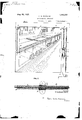
- Fig. 1 is a perspective view of a work-room and workbench laced with my improved fire cable and helical wire conduit.
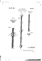
- Fig. 2 is an enlarged side elevation and sectional view of the meeting ends of two spiral wire conduit sections joined together and showing a portion of a fusible control cable extending therethrough.
- Fig. 3 is a side elevation of two short but complete wire conduits connected together and with a control cable therein.
- Fig. 4 is a side View of a short section of wire conduit with a split ferrule sleeved upon one end thereof, and
- Fig. 5 is a perspective view of a clip adapted to receive the said ferrule.
- Fig. 1 is a perspective view of a work-room and workbench laced with my improved fire cable and helical wire conduit.
- Fig. 2 is an enlarged side elevation and sectional view of the meeting ends of two spiral wire conduit sections joined together and showing a portion of a fusible control cable extending therethrough
- FIG. 6 is a cross section of a helical wire conduit section where joined to another like section within a ferrule and clip, this view being taken on line 66 of Fig. 7.
- Fig. 7 is an enlarged side view of two helical conduit sections spirally Serial No. 669,017.
- Bodies 2 are smoothly rounded and tapered or without abrupt or projecting portions at their opposite ends to permit the cable to pass freely around suitable sheaves or pulleys 8 within the building and to slide without being check or retarded or being caught or seized and stopped by any object past which it may move.
- FIG. 1 I show a work table T having a long thermal control cable A secured to one end 4 thereof, the cable being stretched horizontally along one side face of the top of the table to its opposite end where it passes around a sheave 3 and thence upwardly along one side of a column 6 to a second sheave 7, thence horizontally beneath a beam 8 to a third sheave, 9, and thence downwardly and into a rectangular box 10 containing guides for a weight 11 suspended from the cable and adapted to hold it taut.
- a pair of switch buttons or electrical con tacts 12 are situated within the lower end of box 10 beneath weight 11, and an electrical signaling circuit C having a bell 13 or other alarm device is connected to the switch buttons or contacts 12 so that when the weight drops upon fusion of any single bond 2, or is lowered by loosening the cable, an alarm will be given.
- FIG. 1 exemplifies a simple form of lacing a fusible cable for a fire alarm system, but in practice a single thermal control cable, many hundred feet in length, may be laced in a circuitous manner through many rooms and around and beneath and through all sorts of places, including storage bins, trays, balconies, open shafts, etc., and a more extended showing of the lacing of a building with a thermal control cable A is shown in my co-pending application Serial No. 669,016, filed on even date herewith. Reverting to Fig.
- helical wire conduit This permits the helical wire conduit to be fixed to a wall or a wood support with open spaces or interstices between the cable and the wall or support as well as on all other sides thereof, and the heat from a fire on the opposite side of the wall is not cut off from the cable by the conduit itself.
- a helical wire conduit of this kind can be made in any length, and being very flexible it may be readily rolled into a large body for convenient handling and shipment in the same way as the cable.
- the conduit may enclose the cable its entire length, or only at intervals where protection is needed, and to facilitate its assembly and installation together with the cable the helical coil may be easily cut to any given length or divided into sections to fit a given place or condition, and a union or joint between co-extensive helical sections is readily effected. by merely screwing the spiral coil ends together substantially as delineated at 16 in Fig. 7.
- a split sleeve or ferrule 17 may be slipped over the spiral joint to avoid lateral displacement of the wire coils and to permit a clamping holder or clip 18 to be used at this point in fastening the conduit and cable jointly in place upon a wall or other support.
- each helical coil section Only one ferrule 17 is required for each helical coil section, see Fig. at, the opposite end of the coil being left uncovered to permit it to be screw-connected to the ferrule end of another coil section.
- the helical coil being extremely pliable or flexible it is readily fitted to irregular surfaces and may be easily bent and fixed to follow the course of the cable or to serve as a guide for the cable.
- the wire forming each coil is preferably round and may be of any desired gauge depending upon the stiffness or strength re quired, and the wire may be either a soft iron wire or spring wire.
- any given section of coil can be compressed or expanded to shorten or lengthen the section in making interconnections, and the cable can also be cut and spliced to any desired length in lacing a building. From the fore going it will be seen that the cable and helical coil used together provide a very practi cal and useful co-acting assembly in reducing the hazards in a building and that these elements may be jointly installed in a building with a minimum of cost and expense and in a pliant way without difficulty or exacting labor.
- a flexible fusible cable capable of being stretched and com pressed loiwitiicliiially to increase or decrease the size of the openings therein.
- a flexible fusible cable in combination with a helical coil of wire enclosing said cable the coils being permanently spaced apart and open.
- a conduit made of successive open helical coils of wire interconnected at their ends and adapted to enclose and guide a fusible control. cable therein.
- A. conduit made of a series of open helical coils of wire spirally inter-connected at their meeting ends and adapted to enclose and guide a fusible control cable therein.
- An open-work conduit for a fusible control cable made of openly spaced helically wound wire and having a ferrule at one end adapted to facilitate interconnection with a similar open wire conduit.
Description
Aug. 25, E925.
F. W. PARSONS FIRE PROTECTIVE APPLIANCE Filed Oct. 192,3 2 Sheets-Sheet 1 v Fla-Z.
Elma/mm FWPAR SUNS.
Aug. 25, 1925.
v F. w PARSONS mm: PROTECTIVE APPLIANCE F iled Oct. 1923 2 Sheets-Sheet 2 awua wfoz F 5 DNS it 7 .H 3 .1 avvihvvvvum au'071121 S m M WWW q 7) a a1.
Patented Aug. 25, 1925.
UNITED STATES FREDERICK W. PARSONS, OF CLEVELAND, OHIO.
FIRE-PROTECTIVE APPLIANCE.
Application filed. October 17, 1923.
To all whom it may concern:
Be it known that I, FREDERICK W. PAR- SONS, a citizen of the United States, residing at Cleveland, in the county of Guyahoga, and State of Ohio, have invented certain new and useful Improvements in Fire-Protective Appliances, of which the following is a specification.
My invention relates to an improvement in fire protective appliances, and my general object is to provide facile and practical means for lacing a building, or workshop or factory, with a fusible cable and an openwork conduit for the cable. The cable is preferably made in sections joined together by smoothly finished bonds of low fusing solder, such a cable for example as shown in my Letters Patent of the United States, No. 1,455,805, dated May 22, 1923. In use this cable is associated with and adapted to control the operation of any suitable apparatus or device capable of giving warning of a fire or adapted to safe-guard against or put out a fire. To function efiectively the cable must be supported to move or slide freely throughout its length, and to prevent any impedance or possible stoppage of move ment of the cable, while at the same time permitting the fusible bonds to remain constantly in the open or exposed, I find it desirable and advantageous to enclose, guide and protect the cable and its fusible bonds in an open conduit, substantially as hereinafter set forth in detail and more particularly pointed out in the claims.
In the accompanying drawing, Fig. 1 is a perspective view of a work-room and workbench laced with my improved fire cable and helical wire conduit. Fig. 2 is an enlarged side elevation and sectional view of the meeting ends of two spiral wire conduit sections joined together and showing a portion of a fusible control cable extending therethrough. Fig. 3 is a side elevation of two short but complete wire conduits connected together and with a control cable therein. Fig. 4 is a side View of a short section of wire conduit with a split ferrule sleeved upon one end thereof, and Fig. 5 is a perspective view of a clip adapted to receive the said ferrule. Fig. 6 is a cross section of a helical wire conduit section where joined to another like section within a ferrule and clip, this view being taken on line 66 of Fig. 7. Fig. 7 is an enlarged side view of two helical conduit sections spirally Serial No. 669,017.
inter-connected and enclosed within a ferrule and clip.
In lacing a building with a thermal control cable A I prefer to use a flexible wire cable of small diameter made in short sec tions bonded or joined together by relatively small cylindrical bodies 2 of low fusing solder. Bodies 2 are smoothly rounded and tapered or without abrupt or projecting portions at their opposite ends to permit the cable to pass freely around suitable sheaves or pulleys 8 within the building and to slide without being check or retarded or being caught or seized and stopped by any object past which it may move. To illustrate, in Fig. 1 I show a work table T having a long thermal control cable A secured to one end 4 thereof, the cable being stretched horizontally along one side face of the top of the table to its opposite end where it passes around a sheave 3 and thence upwardly along one side of a column 6 to a second sheave 7, thence horizontally beneath a beam 8 to a third sheave, 9, and thence downwardly and into a rectangular box 10 containing guides for a weight 11 suspended from the cable and adapted to hold it taut. A pair of switch buttons or electrical con tacts 12 are situated within the lower end of box 10 beneath weight 11, and an electrical signaling circuit C having a bell 13 or other alarm device is connected to the switch buttons or contacts 12 so that when the weight drops upon fusion of any single bond 2, or is lowered by loosening the cable, an alarm will be given. Fig. 1 exemplifies a simple form of lacing a fusible cable for a fire alarm system, but in practice a single thermal control cable, many hundred feet in length, may be laced in a circuitous manner through many rooms and around and beneath and through all sorts of places, including storage bins, trays, balconies, open shafts, etc., and a more extended showing of the lacing of a building with a thermal control cable A is shown in my co-pending application Serial No. 669,016, filed on even date herewith. Reverting to Fig. 1 herein it will be noted that where the cable is stretched along a table or column or a similarly exposed place there is danger or liability of the cable becoming engaged or held whenever a heavy object is placed against it, such as a packing case, or a roll of goods. In many instances this cable is stretched underneath a work bench, or between rows of filing cabinets or shelves into which goods are shoved and stored and where there is a possibility of the goods coming into contact with the cable unless provision is made to prevent it. I have therefore conceived the idea of using an open work conduit B of relatively small diameter to enclose and protect cable A. In carrying the idea into effect and to obtain the maximum safety with complete fire exposure of the cable and all its fusible bonds, and to pro vide a conduit of low cost adapted to be readily and cheaply installed and quickly connected and also extended to any length in any direction and substantially in as flexible manner as the cable itself, I use a helical coil of wire 15 of slightly larger diameter than the cylindrical bodies or fusible bonds 2 in the cable to permit the cable to slide freely through the helical coil. The coils are open or spaced apart slightly which exposes the cable its full length and on all sides to heat or fire arising in its immediate vicinity. This permits the helical wire conduit to be fixed to a wall or a wood support with open spaces or interstices between the cable and the wall or support as well as on all other sides thereof, and the heat from a fire on the opposite side of the wall is not cut off from the cable by the conduit itself. A helical wire conduit of this kind can be made in any length, and being very flexible it may be readily rolled into a large body for convenient handling and shipment in the same way as the cable. In lacing a building the conduit may enclose the cable its entire length, or only at intervals where protection is needed, and to facilitate its assembly and installation together with the cable the helical coil may be easily cut to any given length or divided into sections to fit a given place or condition, and a union or joint between co-extensive helical sections is readily effected. by merely screwing the spiral coil ends together substantially as delineated at 16 in Fig. 7. A split sleeve or ferrule 17 may be slipped over the spiral joint to avoid lateral displacement of the wire coils and to permit a clamping holder or clip 18 to be used at this point in fastening the conduit and cable jointly in place upon a wall or other support. Only one ferrule 17 is required for each helical coil section, see Fig. at, the opposite end of the coil being left uncovered to permit it to be screw-connected to the ferrule end of another coil section. The helical coil being extremely pliable or flexible it is readily fitted to irregular surfaces and may be easily bent and fixed to follow the course of the cable or to serve as a guide for the cable. The wire forming each coil is preferably round and may be of any desired gauge depending upon the stiffness or strength re quired, and the wire may be either a soft iron wire or spring wire. In lacing a building with a cable and a helical open coil any given section of coil can be compressed or expanded to shorten or lengthen the section in making interconnections, and the cable can also be cut and spliced to any desired length in lacing a building. From the fore going it will be seen that the cable and helical coil used together provide a very practi cal and useful co-acting assembly in reducing the hazards in a building and that these elements may be jointly installed in a building with a minimum of cost and expense and in a pliant way without difficulty or exacting labor.
\Vhat I claim is:
1. In combination, a flexible fusible cable, and a permanently open conduit for said cable capable of being stretched and com pressed loiwitiicliiially to increase or decrease the size of the openings therein.
2. A flexible fusible cable, in combination with a helical coil of wire enclosing said cable the coils being permanently spaced apart and open.
3. A flexible thermal control cable, and a flexible conduit made of permanently open coils sleeved over said cable, said cable and conduit being adapted to be jointly handled and strung in lacing a building.
4. A fusible cable, and a helical open wire coil of small diameter sleeved over said cable and expansible and contractible lengthwise thereof, the ends of the coil being also open to permit inter connection with simi lar open coils.
A conduit made of successive open helical coils of wire interconnected at their ends and adapted to enclose and guide a fusible control. cable therein.
6. A. conduit made of a series of open helical coils of wire spirally inter-connected at their meeting ends and adapted to enclose and guide a fusible control cable therein.
7. An open-work conduit for a fusible control cable, made of openly spaced helically wound wire and having a ferrule at one end adapted to facilitate interconnection with a similar open wire conduit.
In testimony whereof I aliix my signature hereto.
FREDERICK WV. PARSONS.
Priority Applications (1)
| Application Number | Priority Date | Filing Date | Title |
|---|---|---|---|
| US669017A US1550737A (en) | 1923-10-17 | 1923-10-17 | Fire-protective appliance |
Applications Claiming Priority (1)
| Application Number | Priority Date | Filing Date | Title |
|---|---|---|---|
| US669017A US1550737A (en) | 1923-10-17 | 1923-10-17 | Fire-protective appliance |
Publications (1)
| Publication Number | Publication Date |
|---|---|
| US1550737A true US1550737A (en) | 1925-08-25 |
Family
ID=24684682
Family Applications (1)
| Application Number | Title | Priority Date | Filing Date |
|---|---|---|---|
| US669017A Expired - Lifetime US1550737A (en) | 1923-10-17 | 1923-10-17 | Fire-protective appliance |
Country Status (1)
| Country | Link |
|---|---|
| US (1) | US1550737A (en) |
Cited By (1)
| Publication number | Priority date | Publication date | Assignee | Title |
|---|---|---|---|---|
| DE1114390B (en) * | 1955-05-07 | 1961-09-28 | Josef Unger | Automatic fire protection device for flammable goods stored in storage rooms |
-
1923
- 1923-10-17 US US669017A patent/US1550737A/en not_active Expired - Lifetime
Cited By (1)
| Publication number | Priority date | Publication date | Assignee | Title |
|---|---|---|---|---|
| DE1114390B (en) * | 1955-05-07 | 1961-09-28 | Josef Unger | Automatic fire protection device for flammable goods stored in storage rooms |
Similar Documents
| Publication | Publication Date | Title |
|---|---|---|
| US1550737A (en) | Fire-protective appliance | |
| ES2075483T3 (en) | FLEXIBLE PROTECTIVE TUBE FOR LONG ELEMENTS. | |
| US1186741A (en) | Sap-collecting system. | |
| US2197180A (en) | Coiled wire holder | |
| US814472A (en) | Fire-escape | |
| US1422001A (en) | Chimney cleaner | |
| DE607280C (en) | Electric heating device for rollers | |
| GB566679A (en) | Improvements in and connected with supports for electric cables and the like | |
| US1137931A (en) | Cable-armor joint. | |
| US1081498A (en) | Electric-light fixture. | |
| US804365A (en) | Device for preventing contact in telegraph line-wires. | |
| US1110104A (en) | Conveyer for unloading cotton or the like. | |
| US461452A (en) | Electric-wire connector | |
| US647924A (en) | Pulley for overhead telephone-cables. | |
| US1120366A (en) | Fire-starter. | |
| US1246970A (en) | Connection-sleeve for cables. | |
| US1168350A (en) | Lighting-fixture. | |
| US1455805A (en) | Thermal control cable | |
| US1017985A (en) | Hickey. | |
| US1118035A (en) | Conductor-cable support. | |
| US1258051A (en) | Electrical insulator. | |
| US1163618A (en) | Device for capping off glass cylinders. | |
| US401498A (en) | johnson | |
| US816429A (en) | Device for supporting cables of electric lamps. | |
| US426917A (en) | Thermostatic circuit-closer |