US1540468A - Rail end and head support - Google Patents
Rail end and head support Download PDFInfo
- Publication number
- US1540468A US1540468A US753164A US75316424A US1540468A US 1540468 A US1540468 A US 1540468A US 753164 A US753164 A US 753164A US 75316424 A US75316424 A US 75316424A US 1540468 A US1540468 A US 1540468A
- Authority
- US
- United States
- Prior art keywords
- rail
- fish
- shim
- rails
- plate
- Prior art date
- Legal status (The legal status is an assumption and is not a legal conclusion. Google has not performed a legal analysis and makes no representation as to the accuracy of the status listed.)
- Expired - Lifetime
Links
Images
Classifications
-
- E—FIXED CONSTRUCTIONS
- E01—CONSTRUCTION OF ROADS, RAILWAYS, OR BRIDGES
- E01B—PERMANENT WAY; PERMANENT-WAY TOOLS; MACHINES FOR MAKING RAILWAYS OF ALL KINDS
- E01B11/00—Rail joints
- E01B11/02—Dismountable rail joints
Definitions
- My invention relates to improvements in rail end and head supports and has for its primer object .adevice adapted to be inserted etween the fish-plate and the web ofadjacent rails, a portion of-the device extending over the upper edge of the lish-plate so as to fill in the space between the upper edge of the fishlate, and the lower edge of the rail ball anc thus prevent any verticai Y movement of the abutting ends of the-rail.
- a further object is to construct a device or shim which is ada )ted to be used for relaying rails, and whie i is designed to fill 11 that space between the lower edge of the rail ball and the to edge of the fish-plate .or angle bar, and t iereby prevent any vertical movement of the abutting ends of the rails and the elimination of this vertical movement removii all rattle when cars are passing over. the track.
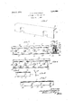
- FIG. 1 is a perspective view of one of the shims employed
- Fig. 2 is a side elevation of a rail show- 'ing the shim in position and supporting the hall of the rails adjacent the abutting ends;
- Fig. 3 is a vertical section taken on the line 3-3 of Fig. 2;
- Fig. 4 is a side elevation of the abutting ends of two rails illustrating the manner of shimming u i the halls of the rails when one of the balls is thinner than the other;
- Fig. 5 is a front elevation of one of the auxiliary shims made use of
- Fig. 6 is an end view of the same.
- Fig. 7 is a modified form of shim when made the complete length of the fish-plate.
- my device I employ a shim composed ofa single piece of metal and having flatportions 8 and 9 arsnugly within the curve formed between theball and web of a railroad rail.
- the portion 9 is provided with open or U shaped slots 11 'web of the rail where the bolts -through.
- portion 12 is provided with an open slot 15 which is similar in shape to the slots '11 but which is so positioned that the edge 16 of the shim will extend to the end of the rail.
- the center of the slot 15 is the-same distance from the edge 16 as the center of the first hole formed through the rail web is from theend oi the rail.
- the other end of the shim has a cut away portion 17 which pernilits it to slide past the next rail bolt.
- Fig. 7 shows a shim which hasportions 18 and 19 and which is provided with slots 20.
- the shim is the same length as the fish-plate and has thesame number of slots therein as there are bolt openings in fish-plate.
- My device is especially useful in relaying rails, that is, rails which have been in use on the main line and which are relaid for sidings, switches, and so forth, as it is almost impossible to get used rails in which the halls have all had the same amount of wear, but by inserting the shims, these tracks can be easily lined up and are practically as noiseless as a new track.
- the shims are made of various thicknesses and in order to cheapen the cost as much as possi- I have found it practical to make the shims out of worn out shovels and scoops and other pieces of scrap sheet metal which accumulates around repair shops, thus doing away with the expense of buying new material as the shims thus constructed serve thepurpose equally'as well.
- My purpose of making one face of the shims relatively wide and providing it with pass over the bolts, is to prevent the shim which permits it to.
- cut away portions extending inwardly rom and at right angles to one of its longitudinal edges, a relatively narrow portion of said sheet adjacent the opposite longitudinal edge beingbent so as to lie at an angle to the remainder of said sheet, to the end that said sheet will lie snugly against the web and between the underside of the ball of a rail and the upper edge of a fish plate, the cut away portion permitting track bolts to pass therethrough and prevent said sheet from creeping when in use.
- a rail end and head support formed from a single piece of sheet metal of substantially uniform width and thickness throughout, and having a wide depending portion provided with elongated laterally extending openings through which bolts for holding fish plates to the rail pass, and with a narrow substantially horizontal portion united to the depending portion by a curve corresponding to the curved surface beneath the ball of a railway rail and to the upper edge of-a fish plate said substantially horizontal portion adapted to be seated between the upper edge of the fish plate and the ball of the rail, the edge of said horizontal ⁇ portion substantially in line with the outer side of the fish plate and the side of the rail ball.
Description
v June 2, 1925. 1,540,463
, E. M. FFFZGERALD RAIL END AND HEAD SUPPORT Filed Dec. 1, 1924 *W 4 fill/1% v Patented June 2, 1925.
UNITED STATES EDWARD M. FITZGERALD, OF SPRINGFIELD, MISSOURI.
RAIL END AND Application filed December To (ZZZ whom it may concern:
Be it known that I, EDWARD M. Frrz- GERALD, a citizen of the United States, and
resident of the city of Springfield,
4 v county of Greene, and State of MlSSOllIl,
have i nvented certain new and useful Improvements in Rail End and Head Supports, of which'the following is a specification con taining a full, clear, and exact description, reference being had to the accompanying drawings, forming a part thereof.
My invention relates to improvements in rail end and head supports and has for its primer object .adevice adapted to be inserted etween the fish-plate and the web ofadjacent rails, a portion of-the device extending over the upper edge of the lish-plate so as to fill in the space between the upper edge of the fishlate, and the lower edge of the rail ball anc thus prevent any verticai Y movement of the abutting ends of the-rail.
ranged at an angle to each other, theintermediate portion .10 being curved so as to fit A further object is to construct a device or shim which is ada )ted to be used for relaying rails, and whie i is designed to fill 11 that space between the lower edge of the rail ball and the to edge of the fish-plate .or angle bar, and t iereby prevent any vertical movement of the abutting ends of the rails and the elimination of this vertical movement removii all rattle when cars are passing over. the track.
In the drawingsz- Fig. 1 is a perspective view of one of the shims employed;
Fig. 2 is a side elevation of a rail show- 'ing the shim in position and supporting the hall of the rails adjacent the abutting ends;
Fig. 3 is a vertical section taken on the line 3-3 of Fig. 2;
Fig. 4 is a side elevation of the abutting ends of two rails illustrating the manner of shimming u i the halls of the rails when one of the balls is thinner than the other;
Fig. 5is a front elevation of one of the auxiliary shims made use of;
Fig. 6 is an end view of the same; and
Fig. 7 is a modified form of shim when made the complete length of the fish-plate.
In the construction of my device I employ a shim composed ofa single piece of metal and having flatportions 8 and 9 arsnugly within the curve formed between theball and web of a railroad rail. The portion 9 is provided with open or U shaped slots 11 'web of the rail where the bolts -through. As soon as this is noticed by the traclewalker the fish-plates HEAD SUPPORT.
1, 1924. Serial No. 753,164.
which are designed to fit over the bolts used in securing the fish-plates to the rail.
In the modification shown in Fig. 5, flat portions 12 and l3 are employed which are =connected together by means of a curved portion 14 which is constructed in the same manner as the shim shown in Fig. 1. The
Fig. 7 shows a shim which hasportions 18 and 19 and which is provided with slots 20. In this instance, however, the shim is the same length as the fish-plate and has thesame number of slots therein as there are bolt openings in fish-plate.
In applying my device I employ rails which are provided with a ball 21, a web 22., and base flanges 23. The web is provided with openings 24 through which bolts 25 pass, these bolts also passing through openings formed in the fish-plates 26. The openings in the fish-plates and in the web of the rail, or": course, correspond. lhc lower edge of the fish-plates is designed to contact with the base flanges of the rail and also with the lower portion of i'hc web and on each side thereof, while the ripper edge of the fish plates is designed to contact with the underside of the ball 21 when layingucw rai ls.
fitter the rails have been in use for a certain length of timo,-continuous pounding of the wheels. over the joint causes the hall ofthe rail to 'wear so that in time an upprcciahle space is formed between the upper edge of the fish plate and the lower surl'ace of the ball, which not only causes the meeting ends of the rail to move up and down when traffic passes thcrcovcr, hut in so doing throws strain on the bolts and. also on the pass thereare loosened up and a shim inserted behind the fish-plate, as illustrated in Figs. 2 ing the hall of the rail to be supported by the upper edge of the and 3, thus again causfish-plate and relieving ble,
the bolts rrom all strain due to-vertical movement of the -rails. in fact, this shim will eliminate. this vertical movement and again make a smooth track. Should it happen that the ball on one'iot' the rails becomes more worn than the other, this is shimmed u') additionally by using the shim shown in Fig. 5 which only extends from the rail joint along the ball which is worn most. Another shim can then be placed beneath the out-turned portion 13 of this shim and the upper edge of the fish-plate, which is clearly shown in Fig. 4.
My device is especially useful in relaying rails, that is, rails which have been in use on the main line and which are relaid for sidings, switches, and so forth, as it is almost impossible to get used rails in which the halls have all had the same amount of wear, but by inserting the shims, these tracks can be easily lined up and are practically as noiseless as a new track.
It is to be understood, of course, that the shims are made of various thicknesses and in order to cheapen the cost as much as possi- I have found it practical to make the shims out of worn out shovels and scoops and other pieces of scrap sheet metal which accumulates around repair shops, thus doing away with the expense of buying new material as the shims thus constructed serve thepurpose equally'as well.
I do not wish my deviceto be confused with the fiber fillers now placed between the fish-plates and rails for insulating the same for block signal purposes, as my deslots open at one end vice is in no sense an insulator but merely a filler to insure proper support of the ball of the rail above the upper edge ofthe fislrplate adjacent the joint so as to prevent vertical movement ot' the abutting rail ends and thereby eliminate unnecessary rattling and clatter over these joints, and by properly supporting the rails and eliminating this vertical movement the tread of the car wheels is also preserved, because if one end of the rail sags down under the pressure, the abutting end or the next rail strikes the tread of the wheel a sharp blow making a dent, this dent with constant rolling becomes a flat place which gradually grows larger and that alone is not. only hard on the rolling stock but also on the track. i
My purpose of making one face of the shims relatively wide and providing it with pass over the bolts, is to prevent the shim which permits it to.
cut away portions extending inwardly rom and at right angles to one of its longitudinal edges, a relatively narrow portion of said sheet adjacent the opposite longitudinal edge beingbent so as to lie at an angle to the remainder of said sheet, to the end that said sheet will lie snugly against the web and between the underside of the ball of a rail and the upper edge of a fish plate, the cut away portion permitting track bolts to pass therethrough and prevent said sheet from creeping when in use. 2. A rail end and head support formed from a single piece of sheet metal of substantially uniform width and thickness throughout, and having a wide depending portion provided with elongated laterally extending openings through which bolts for holding fish plates to the rail pass, and with a narrow substantially horizontal portion united to the depending portion by a curve corresponding to the curved surface beneath the ball of a railway rail and to the upper edge of-a fish plate said substantially horizontal portion adapted to be seated between the upper edge of the fish plate and the ball of the rail, the edge of said horizontal} portion substantially in line with the outer side of the fish plate and the side of the rail ball.
3. A rail end'and head supportformed of a single-plate of sheet metal of uniform width and thicknesssaid plate bent longitudinall adjacent one of its-edges so as to lie snug y along the web and the underside of the ba'll of -a rail, the portion along the web being relatively wide and provided with laterally extending elongated openings, the rail being tightly held there against by the upper edge of a fish plate whereby the. wear on the underside of the rail ball and the upper edge of the fish plate is compensated for and movement of abutting rail ends preented. In testimony whereof, name to this specification.
EDWARD M. FITZGERALD.
portion along the ball of the I have signed my
Priority Applications (1)
| Application Number | Priority Date | Filing Date | Title |
|---|---|---|---|
| US753164A US1540468A (en) | 1924-12-01 | 1924-12-01 | Rail end and head support |
Applications Claiming Priority (1)
| Application Number | Priority Date | Filing Date | Title |
|---|---|---|---|
| US753164A US1540468A (en) | 1924-12-01 | 1924-12-01 | Rail end and head support |
Publications (1)
| Publication Number | Publication Date |
|---|---|
| US1540468A true US1540468A (en) | 1925-06-02 |
Family
ID=25029439
Family Applications (1)
| Application Number | Title | Priority Date | Filing Date |
|---|---|---|---|
| US753164A Expired - Lifetime US1540468A (en) | 1924-12-01 | 1924-12-01 | Rail end and head support |
Country Status (1)
| Country | Link |
|---|---|
| US (1) | US1540468A (en) |
-
1924
- 1924-12-01 US US753164A patent/US1540468A/en not_active Expired - Lifetime
Similar Documents
| Publication | Publication Date | Title |
|---|---|---|
| US1540468A (en) | Rail end and head support | |
| US1045741A (en) | Reinforced-concrete railway-tie. | |
| US1645514A (en) | Railroad tie | |
| US1013960A (en) | Metallic railroad. | |
| US380575A (en) | Street-railway | |
| US1231465A (en) | Railway-rail. | |
| US986899A (en) | Rail-joint and rail-fastener. | |
| US626612A (en) | Metallic cross-tie for railway-tracks | |
| US897592A (en) | Stringer and tie. | |
| US1766367A (en) | Railway-roadbed construction | |
| US898709A (en) | Railroad-tie. | |
| US551688A (en) | Railway-rail and connection | |
| US1766795A (en) | Railway-rail joint | |
| US924931A (en) | Metallic cross-tie and rail-fastener. | |
| US873707A (en) | Tie-plate. | |
| US1562088A (en) | Railway tie | |
| US855755A (en) | Railroad-rail holder. | |
| US1213580A (en) | Railway-track construction. | |
| US793449A (en) | Railroad. | |
| US765603A (en) | Metal railway-tie. | |
| US466942A (en) | Railroad-tie | |
| US446446A (en) | Street-railway track | |
| US1483792A (en) | Anchor tie plate | |
| US1341090A (en) | Railroad-tie | |
| US656986A (en) | Construction of railroad-tracks. |