US1536282A - Shoveling and loading machine - Google Patents
Shoveling and loading machine Download PDFInfo
- Publication number
- US1536282A US1536282A US714559A US71455924A US1536282A US 1536282 A US1536282 A US 1536282A US 714559 A US714559 A US 714559A US 71455924 A US71455924 A US 71455924A US 1536282 A US1536282 A US 1536282A
- Authority
- US
- United States
- Prior art keywords
- shovel
- frame
- base
- oil
- shoveling
- Prior art date
- Legal status (The legal status is an assumption and is not a legal conclusion. Google has not performed a legal analysis and makes no representation as to the accuracy of the status listed.)
- Expired - Lifetime
Links
- 239000012530 fluid Substances 0.000 description 11
- 239000000463 material Substances 0.000 description 10
- 230000033001 locomotion Effects 0.000 description 8
- 238000010276 construction Methods 0.000 description 2
- 239000003245 coal Substances 0.000 description 1
- 238000000151 deposition Methods 0.000 description 1
- 230000010006 flight Effects 0.000 description 1
- 210000004907 gland Anatomy 0.000 description 1
- 238000005065 mining Methods 0.000 description 1
- 230000007935 neutral effect Effects 0.000 description 1
Images


Classifications
-
- E—FIXED CONSTRUCTIONS
- E02—HYDRAULIC ENGINEERING; FOUNDATIONS; SOIL SHIFTING
- E02F—DREDGING; SOIL-SHIFTING
- E02F3/00—Dredgers; Soil-shifting machines
- E02F3/04—Dredgers; Soil-shifting machines mechanically-driven
- E02F3/28—Dredgers; Soil-shifting machines mechanically-driven with digging tools mounted on a dipper- or bucket-arm, i.e. there is either one arm or a pair of arms, e.g. dippers, buckets
- E02F3/34—Dredgers; Soil-shifting machines mechanically-driven with digging tools mounted on a dipper- or bucket-arm, i.e. there is either one arm or a pair of arms, e.g. dippers, buckets with bucket-arms, i.e. a pair of arms, e.g. manufacturing processes, form, geometry, material of bucket-arms directly pivoted on the frames of tractors or self-propelled machines
- E02F3/348—Buckets emptying into a collecting or conveying device
- E02F3/3483—Buckets discharging on a conveyor or elevator mounted on the machine
Definitions
- J. c. BRACKETT SHOVELING AND LOADING MACHINE Filed may 2( 1924 4 She ets-Sheet .5
- MI INVENTOR I T1514 dBrac/ieif HIS ATToia 1 Y Patented May 5, 1925.
- This invention relates to shoveling and loading machines, and more particularly to such machines in which a shovel or scoop is adapted to move through a predetermined cycle of movements.
- the particular type i of machine hereinafter described, is especially designed for use in places such as tunnels. headings of mines and like places in which limited space is provided.
- the movements of the shovel may be resolved into a horizontal thrust toward or away from the material it is desired to opera ate on and a purely circular swinging motion for lifting the loaded shovel upwardly and back to the point at which the material is .to be deposited.
- the forward thrust is accomplished by meansof plungers supporting the shovel and the circular motion is accomplished by 'a device supported by the plungers and swinging the shovel about a pivot fixed with respect to the plungers.
- This invention also contemplates the use of a conveyor of the endless type in which the material is unloaded from theshovel and by which itis carried back and removed to a suitable receptacle such as the usual mining car.
- Figure 1 is a side elevation of a shovel ing and loading machine constructed in accordance with the practice of the inven tion;
- Figure 2 is a plan view of the machine showing more particularly the conveyor
- Figure 3 is a side elevation of the machine partly in section to show the means for directing the shovel with respect to the material which it is desired to remove and the means for horizontally ad ust1ng the conveyor mechanlsm;
- Figure 4 is a horizontal section through the machine showing the internal construction of the device for directing the shovel toward the material to be removed and more particularly the internal construction of the cylinders and associated plungers for'thrusting the shovel longitudinally;
- Figure 5 is a cross sectional detail view of the swivel joint about which the shovel supporting frame and the conveyor are pivoted;
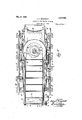
- Figure 6 is a cross section taken along the line 66 of Figure 2 looking in the direction of the arrows through the device for swinging the shovel in this circular motion to its dumping position;
- Figure 7 is a cross section of the device shown in Figure 6 taken along the line 7- 1 of Figure 2 looking in the direction of the arrows.
- the machine includes a wheeled base A, a frame B supported on the base, adapted to be swung horizontally for adjusting the direction of A center pin K ( Figure 3) forms a pivot about whichboth the frame B and the conveyor F may be swung.
- two cylinders L are formed integrally with the frame 3 preferably on either side of the frame and are each provided with a piston O at tached as by screw threaded engagement to the endsof the plungers D.
- a source of pressure fluid such as the gear pump P mounted 011 the rearward end of the frame B, is adapted to supply a fluid such as oil to the interior of the cylinders L for ac tuating the plungers D.
- the gear pump 1. is in a state of continuous operation and to this end a direct connected electric motor Q, also mounted on the frame B, supplies the motive power to the pump P for continuously maintaining, a circulation of oil to and from an oil reservoir B through a suitable bypass S.
- A. spring pressedvalve T resists the flow of oil in the by-pass S and in this manner the desired pressure in the oil supply is maintained.
- the oil under pressure from the pump P is admitted through pipes U associated with the source oi supply by means of a valve V which is connected by means of a pipe iv to the pump supply and by a pipe X with the reservoir R.
- the valve V is controlled by means of a lever Y which is directly connected with the valve V.
- oil is supplied from the pump P through the pipe iv, the valve V and the pipes U to the bacl; of the cylinders L.
- the pipes U are connected to the pipe X leading, to the reservoir R permitting the oil to tlowbaclr from the rear end of the cylinders L into the reservoir H.
- the shovel C mounted on a pair of arms Z) :t'astencd to opposite ends of a shat't which is rotatably mounted on a littinp; device supported by the plungi crs and adapt cd to swing the shovel about the shaft 0 as a pivot, the axis of which is lined with respect to the ends of the plungers l).
- the device for rot: 'ing the shaft 0 to hit the shovel C consists of a cylindrical chamber (Z concentric with the shaft 0 and having a.
- the. chamber (Z is not a complete. cylinder since the piston 0 does not describe a complete revolution. Accordingly a stationary head 7' is provided at .the limiting positions of the piston e.
- oil under. pressure is supplied from. the pump Pto the rearward side of the piston a through a port 9 ( Figure 6).
- oil is adapted to be introduced into the chamber (Z at the forward face of the piston e througl'i a port 7b which provides pressure to force the oil back through the port o into the reservoir R.
- The'supply of oil to the chamber (Z is controlled by a pair of valves j and which may be operated by a control lever Z, these valves being;' adapted to control the flow of. oil through pipes 0 and 0 connected with tubes 7) and p" extending); longitudinally into the cylinders L and communicating: with passages and y in the plungers D'leading to the ports y and ll respectively.
- Suitable return pipes r and 1" lead from the valves j and y" respectively to the reservoir R.
- the valves and j l;(% lug directly connected to each other and with the lever is are arranged so that when one of these valves connects its respective pipe with the supply from the pump P, the other connects its pipe with the return pip-c.
- the plungers D may be made integrally with the cylindrical chamber (Z thereby insuring rigidity.
- the shovel C is drawn baclc by manipulation of the lever Y controlling the valve V.
- the shovel C is then lowered by admitting oil through the port It as above descril md. l l ith the shovel in. its lowered position, the valve V is then operated by means of the lever Y to adi'nit' oil into the rear end of the cylinders L, tin-listing the shovel l'm'ward into the pile of material to be removed.
- the shovel having been thrust forward and filled, the control lever Z: is then operated to admit the oil under pressure through the port r thereby rotating the shovel C.
- oil is admitted by means of the valve V to the front end of the cylinders L to withdraw the shovel.
- the shovel, therct'orc moves through a circulararc and backward to its dunuginp position.
- the coal or other material isv dumped from the shovel G into a hopper a above a conveyor o by which it is carried back and dumped into a suitable receptacle, such as a car G.
- the conveyor '0 ( Figure 2) is provided with side chains to by which it is pro pelled and which support flights pivoted on rods 3 secured at their opposite ends to the side chains 10.
- ahousing wnich assists in guiding the belt.
- the upper run o adapted to slide on a plate 2 suitably secured to the sides of the housing Suitable means may be provided to op crate the conveyor o, such as an electric motor 8 provided with a worm st meshing with a worm wheel 5 on the end of a shaft 6 to which are attached a pair of sprockets llf) 7 for the chains to.
- a shaft 8 adjacent the opposite end" of the conveyor F is provided with a pair of similar sprockets 9 for guiding thechains w. r
- the n 9 yer bearing race 11 forms the base of the con veyor F which is held against tipping by a retainer 12 held on the center pin ll-bv suitably attached to the rearward end of the conveyor F] to support the rear end of the'conveyor F.
- the hopper a is constructed partly circular so as to receive the material from the shovel C regardlessof the angle at which the conv yor if is turned with respect to the frame B.
- the base B is also adapted to be turned about the center pin K as a pivot.
- the frame 1]?) is supported on anti-friction bearings 19 on which the circular race 20 is adapted to turn.
- the frame B isordinarily too heavy to be swung easily by hand and therefore,power driven means are provided for performing this function.
- a cylinder 21 is formed in the frame ll with the piu K as acenter. The top of this (,xylinder is closed by the lower race22 for the bearings 10.
- a flat piston 23 keyed to the center pin K is adapted to receive on either side [iuid pressure of oil introduced through apertures 24 and associated with pipes 26 and 27 leading to the valve 28.
- supply pipe 29 connects the discharge side of the pump P with the valve 28 and a re turn pipe 30 connects the valve 28 with the reservoir R, Alcver 31 controls the valve 28.
- the cylinder 21 is divided into two compartments by the piston 23 and a head rigidly attached to the wall of the cylinder 2i, one of the compartments being supplied with. oil from the aperture 2d and the other being supplied through the aperture 25.
- the valve QS so arranged that when the supply pipe 29 is connected with one or the other of the pipes 26 and 27, theother pipe'is connected with the return pipe 30.
- the other compartment is being exhausted.
- Oil entering by the aperture 25, by reaction causes pressure against the piston 23 and rotates the cylinder and the frame 13 countei clockwise. Similarly when oil is forced through the aperture 24 the motion of the frame B is clockwise. Very accurate pointing of the shovel G in the proper position may thus be obtained.
- the machine may be propelled in any desired manner. Being heavy it is preferred to provide a power drive, such as the electric motor 33 for driving the flanged wheels H through suitable gearing as for instance, a worm wheel and worm (not shown).
- a power drive such as the electric motor 33 for driving the flanged wheels H through suitable gearing as for instance, a worm wheel and worm (not shown).
- the wheels H may be spaced at any desired gauge so as to fit as for instance, the railway tracks 34. l
- a shoveling and loading machine comprising the combination of a base, a shovel, means for thrusting said shovel forwardly and back, means including a cylindrical pressure chamber, and a pivotally supported flat piston swinging in said pressure chamher for raising and dumping said shovel.
- a shoveling and loading machine 0011 1, prising the combination of a base, a frame pivotally supported on said base, a shovel,
- means for thrusting said shovel forwardly and back means including a cylindrical pressure chamber and pivotally supported flat piston swinging in said pressure chain her for raising and dumping saidlshovel.
- a shoveling and loading machine com prising the COlIllOlUtItlOll of abase, a frame, a shovel, means mounted on said frame for thrusting said shovel forwardly and back, and means including a cylindrical pressure chamber and a pivotally supported flat piston swinging in said pressure chamber for raising and drunping said shovel.
- a shoveling and loading machine comprising the combination of a base, a frame PlVOtitllff supported on said base, a shovel, means mounted on said frame for thrusting said shovel forwardly and back and means including a cylindrical pressure chamber and a pivotally supported flat pis ton in said pressure chamber for raising and dumping said shovel.
- a shoveling and loading machine comprising the combination of a base, a frame pivotally supported on said base, a shovel, fluid actuated plungers mounted on said frame for thrusting said shovel forwardly and back, means including a cylindrical pressure chamber mounted on said plungers, and a fluid actuated piston rotatably mounted in said chamber for raising and dumping said shovel.
- a shoveling and loading machine comprising the combination of a base, a frame on said base, a shovel, means associated with said frame to thrust said shovel forwardly and back, means for raising and dumping said shovel, means including a cylindrical pressure chamber, and a relatively rotatable fluid actuated flat piston in said cylinder for swinging said frame with respect to said base.
- a shoveling and loading machine comprising the combination of a base, a frame on said base, a shovel, means on saidframe for thrusting said shovel forwardly and back, means to raise and dump said shovel, means including a cylindrical pressure chamber formed in said frame, and a relatively rotatable fluid actuated flat piston fixed-With respect to said base to swing said frame with respect to said base.
- a shoveling. and loading machine comprising the combination of a base, a frame mounted on said base, a shovel, means sup ported by said frame for thrusting said shovel forwardly and back, means for raising and dumping said shovel, means including a center: pin supported on said base, a cylindrical pressure chamber concentric with said center pin and stationary with respect to said frame, and a relatively rotatable fluid actuated fiat piston in said chamber and attached to said center pin to swing said-frame with respect to said base.
- a shoveling and loading machine comprising the combinationof a base, a frame v supported by said base, a shovel, plungers on sa1d basefor thrustlng sa1d shovel forwardly and back,- means for raising. and dump ng said shovel, means including a cy lindrical pressure chamber, and a relatively rotatable fluid actuated flat piston in said cylinder for swinging said frame with respect to said base.
- a shoveling and loading machine comprising the combination of a base, a frame on said base, a shovel, fluid actuated plungers supported by said frame, a pressure chamber on said plunger-s, a rotatable fluid actuated fiat piston rotatable in said cylinder andadapted to raise and dump said shovel, means including a cylindrical pressure chamber, and a relatively rotatable fluid actuated flat piston in said cylinder for swinging said frame with respect to said base.
- a shoveling and loading machine comprising the combination of a base, a frame supported by said base, a shovel, plungers mounted on said frame and adapted to thrust said shovel forwardly and back, a cylindrical pressure chamber mounted on said plunger-s, a flat rotatable piston within said chamber adapted to raise and dump said shovel, said chamber having a concave outer surface to guide the material dumped from said shovel, and a con veyor having a circular hopper cooperating with said concave outer surface of the pressure chamber to receive the material dumped from said shovel.
Landscapes
- Engineering & Computer Science (AREA)
- Mechanical Engineering (AREA)
- Mining & Mineral Resources (AREA)
- Civil Engineering (AREA)
- General Engineering & Computer Science (AREA)
- Structural Engineering (AREA)
- Operation Control Of Excavators (AREA)
Description
May 5, 1925. 1,536,282
' J. c. BRACKETT SHOVELING AND LOADING MACHINE Filed May 20. 19 4 4 Sheets-Sheet 1 INVENTOR i 75 A); afinaclfeff Mali 5, 1925.
J. c. BRACKETT SHOVELING AND LOADING MACHINE Filed may 2( 1924 4 She ets-Sheet .5
INN
INVENTOR v i (u HIS ATTO EY May 5, 1925. 1,536,282
J. CQIBRACKETT SHOVELING AND. LOADING mourns FiledJJay 2 1924 4 Sheets-Sheet 4 il l lli
in MI INVENTOR I T1514]: dBrac/ieif HIS ATToia 1 Y Patented May 5, 1925.
UNITED STATES PATENT OFFICE.
JOHN c. naacxarr, 0F rHILLIrsnUne, new JERSEY, ASSIGNOR r0 INGERSOLL-RAND COMPANY, or JERSEY CITY, NEW JERSEY, A coaroaarron on NEW JERSEY.
SHOVELII'IG- AND LQADING MACHINE.
Application filed. May 20, 1924. Serial No, 714,559.
To all 107mm it may concern:
Be it known that I, J OHN C. BRACKETT, a citizen of the United States, and a resident of Phillipsburg, county of Warren, and State of New Jersey, have invented a certain Shoveling and Loading Machine, of
which the following is a specification, accompanied by drawings.
This invention relates to shoveling and loading machines, and more particularly to such machines in which a shovel or scoop is adapted to move through a predetermined cycle of movements. The particular type i of machine, hereinafter described, is especially designed for use in places such as tunnels. headings of mines and like places in which limited space is provided.
It is'an object of this invention tosimplify the movements of the shovel in lifting its load and depositing it in a suitable receptacle. In the preferred embodiment hereinafter described, the movements of the shovel, independent of the mechanism provided for directing its action, may be resolved into a horizontal thrust toward or away from the material it is desired to opera ate on and a purely circular swinging motion for lifting the loaded shovel upwardly and back to the point at which the material is .to be deposited. Preferably, the forward thrust is accomplished by meansof plungers supporting the shovel and the circular motion is accomplished by 'a device supported by the plungers and swinging the shovel about a pivot fixed with respect to the plungers. This invention also contemplates the use of a conveyor of the endless type in which the material is unloaded from theshovel and by which itis carried back and removed to a suitable receptacle such as the usual mining car.
The invention will be more clearly under stood by reference to the following description taken in connection with the drawings, in which-.-
Figure 1 is a side elevation of a shovel ing and loading machine constructed in accordance with the practice of the inven tion;
Figure 2 is a plan view of the machine showing more particularly the conveyor;
Figure 3 is a side elevation of the machine partly in section to show the means for directing the shovel with respect to the material which it is desired to remove and the means for horizontally ad ust1ng the conveyor mechanlsm;
Figure 4 is a horizontal section through the machine showing the internal construction of the device for directing the shovel toward the material to be removed and more particularly the internal construction of the cylinders and associated plungers for'thrusting the shovel longitudinally;
Figure 5 is a cross sectional detail view of the swivel joint about which the shovel supporting frame and the conveyor are pivoted;
Figure 6 is a cross section taken along the line 66 of Figure 2 looking in the direction of the arrows through the device for swinging the shovel in this circular motion to its dumping position; and
Figure 7 is a cross section of the device shown in Figure 6 taken along the line 7- 1 of Figure 2 looking in the direction of the arrows.
Referring to the drawings, the machine includes a wheeled base A, a frame B supported on the base, adapted to be swung horizontally for adjusting the direction of A center pin K (Figure 3) forms a pivot about whichboth the frame B and the conveyor F may be swung.
To operate the plungers for the pun pose of thrusting the shovel C, two cylinders L are formed integrally with the frame 3 preferably on either side of the frame and are each provided with a piston O at tached as by screw threaded engagement to the endsof the plungers D. A source of pressure fluid, such as the gear pump P mounted 011 the rearward end of the frame B, is adapted to supply a fluid such as oil to the interior of the cylinders L for ac tuating the plungers D.
Preferably, the gear pump 1. is in a state of continuous operation and to this enda direct connected electric motor Q, also mounted on the frame B, supplies the motive power to the pump P for continuously maintaining, a circulation of oil to and from an oil reservoir B through a suitable bypass S. A. spring pressedvalve T resists the flow of oil in the by-pass S and in this manner the desired pressure in the oil supply is maintained.
To thrust the plun-gcrs 1) forward, the oil under pressure from the pump P is admitted through pipes U associated with the source oi supply by means of a valve V which is connected by means of a pipe iv to the pump supply and by a pipe X with the reservoir R. The valve V is controlled by means of a lever Y which is directly connected with the valve V. In one position of the valve V, oil is supplied from the pump P through the pipe iv, the valve V and the pipes U to the bacl; of the cylinders L. In another position of the alve V, the pipes U are connected to the pipe X leading, to the reservoir R permitting the oil to tlowbaclr from the rear end of the cylinders L into the reservoir H. An additional pair of pipes Zlead to the front end of the cylindersL and in the last mentioned positionoi the valve V oil is supplied through these pipes to provide pressure against the pistons O to withdraw the plungers D. .ln the neutral position of the valve V, the oil .is trapped in-both ends of the cylinders L anduo more is supplied to or returned therefrom.
The shovel C mounted on a pair of arms Z) :t'astencd to opposite ends of a shat't which is rotatably mounted on a littinp; device supported by the plungi crs and adapt cd to swing the shovel about the shaft 0 as a pivot, the axis of which is lined with respect to the ends of the plungers l). The device for rot: 'ing the shaft 0 to hit the shovel C consists of a cylindrical chamber (Z concentric with the shaft 0 and having a.
llat. piston e secured to the shaft (1 for rotation within the chamber (Z. Preferably, the. chamber (Z is not a complete. cylinder since the piston 0 does not describe a complete revolution. Accordingly a stationary head 7' is provided at .the limiting positions of the piston e. Inorder to raise the shovel C, oil under. pressure is supplied from. the pump Pto the rearward side of the piston a through a port 9 (Figure 6). For reversing this movement of the shovel C, oil is adapted to be introduced into the chamber (Z at the forward face of the piston e througl'i a port 7b which provides pressure to force the oil back through the port o into the reservoir R. The'supply of oil to the chamber (Z is controlled by a pair of valves j and which may be operated by a control lever Z, these valves being;' adapted to control the flow of. oil through pipes 0 and 0 connected with tubes 7) and p" extending); longitudinally into the cylinders L and communicating: with passages and y in the plungers D'leading to the ports y and ll respectively. Suitable return pipes r and 1" lead from the valves j and y" respectively to the reservoir R. The valves and j l;(% lug directly connected to each other and with the lever is are arranged so that when one of these valves connects its respective pipe with the supply from the pump P, the other connects its pipe with the return pip-c. Thus, for instance, as oil is being forced into the chamber (Z through the port 7, oil is simultaneously being forced out of the chamber (Z through the return pipe r into the reservoir P.
The tubes p and 7) preterably telescope with the plunger-s D and preferably, the sliding surfaces of these tubes and the passages Q and g are made to lit accurately. Leakage from the cylinders L is prevented by means of suitable glands 8 within which the plungcrs D are adapted to slide. The plungers D may be made integrally with the cylindrical chamber (Z thereby insuring rigidity.
In operation, the shovel C is drawn baclc by manipulation of the lever Y controlling the valve V. The shovel C is then lowered by admitting oil through the port It as above descril md. l l ith the shovel in. its lowered position, the valve V is then operated by means of the lever Y to adi'nit' oil into the rear end of the cylinders L, tin-listing the shovel l'm'ward into the pile of material to be removed. The shovel having been thrust forward and filled, the control lever Z: is then operated to admit the oil under pressure through the port r thereby rotating the shovel C. Sunultancously, oil is admitted by means of the valve V to the front end of the cylinders L to withdraw the shovel. The shovel, therct'orc, moves through a circulararc and backward to its dunuginp position.
The coal or other material isv dumped from the shovel G into a hopper a above a conveyor o by which it is carried back and dumped into a suitable receptacle, such as a car G. The conveyor '0 (Figure 2) is provided with side chains to by which it is pro pelled and which support flights pivoted on rods 3 secured at their opposite ends to the side chains 10. At thesidesand bottom there is provided ahousing wnich assists in guiding the belt. The upper run o adapted to slide on a plate 2 suitably secured to the sides of the housing Suitable means may be provided to op crate the conveyor o, such as an electric motor 8 provided with a worm st meshing with a worm wheel 5 on the end of a shaft 6 to which are attached a pair of sprockets llf) 7 for the chains to. A shaft 8 adjacent the opposite end" of the conveyor F is provided with a pair of similar sprockets 9 for guiding thechains w. r
The conveyorF 1s mounted on Etlltl-fllC tion bearm 's 10 on the frame B. The n 9 yer bearing race 11 forms the base of the con veyor F which is held against tipping by a retainer 12 held on the center pin ll-bv suitably attached to the rearward end of the conveyor F] to support the rear end of the'conveyor F.
Being provided with the 2tlltlf1'1C'tlO11 bearings 10 and let the conveyor may be swung about the centerpinfK a pivot to any desiredrearward direction. The hopper a is constructed partly circular so as to receive the material from the shovel C regardlessof the angle at which the conv yor if is turned with respect to the frame B.
In practice it becomes desirable to direct the shovel (J in a great variety of directions and therefore, the base B is also adapted to be turned about the center pin K as a pivot.
The frame 1]?) is supported on anti-friction bearings 19 on which the circular race 20 is adapted to turn. The frame B isordinarily too heavy to be swung easily by hand and therefore,power driven means are provided for performing this function. For this purpose a cylinder 21 is formed in the frame ll with the piu K as acenter. The top of this (,xylinder is closed by the lower race22 for the bearings 10. A flat piston 23 keyed to the center pin K is adapted to receive on either side [iuid pressure of oil introduced through apertures 24 and associated with pipes 26 and 27 leading to the valve 28. A
The machine may be propelled in any desired manner. Being heavy it is preferred to provide a power drive, such as the electric motor 33 for driving the flanged wheels H through suitable gearing as for instance, a worm wheel and worm (not shown). The wheels H may be spaced at any desired gauge so as to fit as for instance, the railway tracks 34. l
I claim:
1. A shoveling and loading machine, comprising the combination of a base, a shovel, means for thrusting said shovel forwardly and back, means including a cylindrical pressure chamber, and a pivotally supported flat piston swinging in said pressure chamher for raising and dumping said shovel.
52. A shoveling and loading machine, 0011 1, prising the combination of a base, a frame pivotally supported on said base, a shovel,
means for thrusting said shovel forwardly and back, means including a cylindrical pressure chamber and pivotally supported flat piston swinging in said pressure chain her for raising and dumping saidlshovel.
3. A shoveling and loading machine, com prising the COlIllOlUtItlOll of abase, a frame, a shovel, means mounted on said frame for thrusting said shovel forwardly and back, and means including a cylindrical pressure chamber and a pivotally supported flat piston swinging in said pressure chamber for raising and drunping said shovel.
l. A shoveling and loading machine, comprising the combination of a base, a frame PlVOtitllff supported on said base, a shovel, means mounted on said frame for thrusting said shovel forwardly and back and means including a cylindrical pressure chamber and a pivotally supported flat pis ton in said pressure chamber for raising and dumping said shovel.
5. A shoveling and loading machine, comprising the combination of a base, a frame pivotally supported on said base, a shovel, fluid actuated plungers mounted on said frame for thrusting said shovel forwardly and back, means including a cylindrical pressure chamber mounted on said plungers, and a fluid actuated piston rotatably mounted in said chamber for raising and dumping said shovel.
6. A shoveling and loading machine, comprising the combination of a base, a frame on said base, a shovel, means associated with said frame to thrust said shovel forwardly and back, means for raising and dumping said shovel, means including a cylindrical pressure chamber, and a relatively rotatable fluid actuated flat piston in said cylinder for swinging said frame with respect to said base.
7. A shoveling and loading machine, comprising the combination of a base, a frame on said base, a shovel, means on saidframe for thrusting said shovel forwardly and back, means to raise and dump said shovel, means including a cylindrical pressure chamber formed in said frame, and a relatively rotatable fluid actuated flat piston fixed-With respect to said base to swing said frame with respect to said base.
8. A shoveling. and loading machine, comprising the combination of a base, a frame mounted on said base, a shovel, means sup ported by said frame for thrusting said shovel forwardly and back, means for raising and dumping said shovel, means including a center: pin supported on said base, a cylindrical pressure chamber concentric with said center pin and stationary with respect to said frame, and a relatively rotatable fluid actuated fiat piston in said chamber and attached to said center pin to swing said-frame with respect to said base.
9. A shoveling and loading machine, comprising the combinationof a base, a frame v supported by said base, a shovel, plungers on sa1d basefor thrustlng sa1d shovel forwardly and back,- means for raising. and dump ng said shovel, means including a cy lindrical pressure chamber, and a relatively rotatable fluid actuated flat piston in said cylinder for swinging said frame with respect to said base. I
10. A shoveling and loading machine, comprising the combination of a base, a frame on said base, a shovel, fluid actuated plungers supported by said frame, a pressure chamber on said plunger-s, a rotatable fluid actuated fiat piston rotatable in said cylinder andadapted to raise and dump said shovel, means including a cylindrical pressure chamber, and a relatively rotatable fluid actuated flat piston in said cylinder for swinging said frame with respect to said base.
11. A shoveling and loading machine, comprising the combination of a base, a frame supported by said base, a shovel, plungers mounted on said frame and adapted to thrust said shovel forwardly and back, a cylindrical pressure chamber mounted on said plunger-s, a flat rotatable piston within said chamber adapted to raise and dump said shovel, said chamber having a concave outer surface to guide the material dumped from said shovel, and a con veyor having a circular hopper cooperating with said concave outer surface of the pressure chamber to receive the material dumped from said shovel.
In testimony whereof I have signed this specification.
JOHN C. BRACKETT.
Priority Applications (1)
| Application Number | Priority Date | Filing Date | Title |
|---|---|---|---|
| US714559A US1536282A (en) | 1924-05-20 | 1924-05-20 | Shoveling and loading machine |
Applications Claiming Priority (1)
| Application Number | Priority Date | Filing Date | Title |
|---|---|---|---|
| US714559A US1536282A (en) | 1924-05-20 | 1924-05-20 | Shoveling and loading machine |
Publications (1)
| Publication Number | Publication Date |
|---|---|
| US1536282A true US1536282A (en) | 1925-05-05 |
Family
ID=24870520
Family Applications (1)
| Application Number | Title | Priority Date | Filing Date |
|---|---|---|---|
| US714559A Expired - Lifetime US1536282A (en) | 1924-05-20 | 1924-05-20 | Shoveling and loading machine |
Country Status (1)
| Country | Link |
|---|---|
| US (1) | US1536282A (en) |
Cited By (6)
| Publication number | Priority date | Publication date | Assignee | Title |
|---|---|---|---|---|
| US2417544A (en) * | 1944-10-16 | 1947-03-18 | Marion P Mccaffrey | Material handling apparatus |
| DE891529C (en) * | 1941-04-16 | 1953-09-28 | Moenninghoff Maschf | Loading machine for underground operation |
| DE904279C (en) * | 1951-11-22 | 1954-02-18 | Kloeckner Humboldt Deutz Ag | Shovel loading machine |
| US2746625A (en) * | 1951-08-09 | 1956-05-22 | Eimco Corp | Pivoted bucket loader |
| DE1093730B (en) * | 1957-11-28 | 1960-11-24 | Duesterloh Fabrik Fuer Bergwer | Mobile throwing shovel loader |
| DE1266228B (en) * | 1961-09-20 | 1968-04-11 | Landsverk Ab | Loading machine |
-
1924
- 1924-05-20 US US714559A patent/US1536282A/en not_active Expired - Lifetime
Cited By (6)
| Publication number | Priority date | Publication date | Assignee | Title |
|---|---|---|---|---|
| DE891529C (en) * | 1941-04-16 | 1953-09-28 | Moenninghoff Maschf | Loading machine for underground operation |
| US2417544A (en) * | 1944-10-16 | 1947-03-18 | Marion P Mccaffrey | Material handling apparatus |
| US2746625A (en) * | 1951-08-09 | 1956-05-22 | Eimco Corp | Pivoted bucket loader |
| DE904279C (en) * | 1951-11-22 | 1954-02-18 | Kloeckner Humboldt Deutz Ag | Shovel loading machine |
| DE1093730B (en) * | 1957-11-28 | 1960-11-24 | Duesterloh Fabrik Fuer Bergwer | Mobile throwing shovel loader |
| DE1266228B (en) * | 1961-09-20 | 1968-04-11 | Landsverk Ab | Loading machine |
Similar Documents
| Publication | Publication Date | Title |
|---|---|---|
| US2537010A (en) | Tractor mounted shovel and front end loader | |
| US2712876A (en) | Self-loading and dumping vehicle | |
| US2413096A (en) | Portable loading machine | |
| US2099981A (en) | Material loading apparatus | |
| US1536282A (en) | Shoveling and loading machine | |
| US3091874A (en) | High speed excavating machine | |
| US1692121A (en) | Truck | |
| US3896571A (en) | Multi-wheeled excavator and conveying system | |
| US1908434A (en) | Loading machine | |
| US1321983A (en) | Pneumatic shovel. | |
| US2785761A (en) | Apparatus for walking heavy structures | |
| US3406851A (en) | Self-loading power driven dump vehicles | |
| US2152700A (en) | Heavy duty scraper | |
| US1783787A (en) | Excavating machine | |
| US1472563A (en) | Trenching machine | |
| US2394006A (en) | Material haulage vehicle | |
| US884960A (en) | Excavator. | |
| US2527928A (en) | Power shovel and loader | |
| US1472907A (en) | Loading machine | |
| US1128151A (en) | Excavating-machine. | |
| US388910A (en) | Excavator | |
| US2334770A (en) | Mining machine | |
| US2638200A (en) | Loading machine | |
| US1535381A (en) | Shoveling machine | |
| USRE17467E (en) | crawford |