US1521271A - Can opener - Google Patents
Can opener Download PDFInfo
- Publication number
- US1521271A US1521271A US501609A US50160921A US1521271A US 1521271 A US1521271 A US 1521271A US 501609 A US501609 A US 501609A US 50160921 A US50160921 A US 50160921A US 1521271 A US1521271 A US 1521271A
- Authority
- US
- United States
- Prior art keywords
- cutter
- bar
- opened
- cans
- base
- Prior art date
- Legal status (The legal status is an assumption and is not a legal conclusion. Google has not performed a legal analysis and makes no representation as to the accuracy of the status listed.)
- Expired - Lifetime
Links
Images


Classifications
-
- B—PERFORMING OPERATIONS; TRANSPORTING
- B67—OPENING, CLOSING OR CLEANING BOTTLES, JARS OR SIMILAR CONTAINERS; LIQUID HANDLING
- B67B—APPLYING CLOSURE MEMBERS TO BOTTLES JARS, OR SIMILAR CONTAINERS; OPENING CLOSED CONTAINERS
- B67B7/00—Hand- or power-operated devices for opening closed containers
- B67B7/30—Hand-operated cutting devices
Definitions
- This invention relates to can openers and has for its object the provision of a can opening machine designed primarily for use in hotels, restaurants, ships, barracks, and other places where a large number of cans must be opened in a short time, the construction of the device being such that a can may f be opened-at one stroke of a lever, the machine being equally well adapted for use regardless of the size or shape of the cans to be opened.
- the essential feature is the provision of a centering member for holding the cans in proper position to be engagedvby the cutter, the centering member being so constructed as to hold a can to prevent it from being drawnupwardly in case the cutter sticks in the cut edges of the cans.
- An additional object is the provision of a machine of this character which will be simple and inexpensive in manufacture, highly eflicient in use, easy to operate, durable in service, and a general improvement in the art.
- Figure 2 is an elevation taken at right angles to Figure 1, Y
- Figure 3 is a horizontal sectional view taken On the line 3 3 of Figure 1,
- Figure 4e is a cross sectional view taken immediately above the operating lever, on
- Figure 5 is a cross sectional view line 5--5g'of Figure 1
- Figure 6 is a detail longitudinal sectional view through the base'and centering guide showing a can engaged in the latter
- Figure 7 is a bottom plan view of the circular cutter
- Figure 8 is a bottom cutter,A
- Figure 10 is a side elevation ,of a straight ings, the numeral 15 designates a suitable base which may be disposed at any preferred height and which may be supported by any suitable means as for instance by being secured upon a table. shelf or other support.
- a standard 16 Secured upon and rising from this base is a standard 16 which is shown as being rectangular in cross section and secured upon which standard in spaced relation to each other, are yokes 17 which are of elongated loop formation and which are riveted to the standard, as shown at 18.
- Slidable through these yokes is a vertically disposed bar 19 which is formed with a plurality of holes 20 for a purpose to be described.
- links 22 Disposed on opposite sides of the standard and pivoted thereto, as shown at 21, are links 22 with the lower ends of which are pivotally con nected levers 23 which are pivotally connected with the bar 19 by means of a suitable pin 24 passing through a selected one of the holes 20.
- the levers 23 are of any desired length and are to be moved to move the bar 19 up and down through the guide yokes 17.
- a centering guide for properly centering the can to be opened and it will of course be understood that there must be a set of these centering guides, depending upon the shape and size of cans to be opened.
- the centering guide as formed of a suitable plate 26 having its smaller end formed with a slot 27 adapted to be slipped onto the lower end of the standard 16.
- a U-shaped clip 28 for preventing upward movement of the guide I provide a U-shaped clip 28 which is disposed in straddling relation upon the lower end of the standard and y held thereon by a suitable transverse pin 29.
- the plate 26 is easily slipped under the clip 28.
- This guide, or the plate 26 has Vits wider end formed with a recess corresponding to the size and shape of the can to be opened.
- Thisv ilange of cou-rse operates to hold the can down.
- a cutter Secured upon the lower end of the member 19 is a cutter which can be of dili'erent sizes and shapes, depending kupon the cans to be opened.
- this cutter as comprisingk a circular disk 32 provided centrally with a socket 33 which receives the lower end of the bar 19',4 this through and into the flange.- It'will be seen that the lower edge of this blade is formed with teeth 38 which are o'f course pointed and which have their edges sharpened.
- the cutter includes a blockl 43- carrying a socket 44 for engagement upon the bar, and having a longitudinaly slot 45 within' which is secured a straight blade 46.
- The' operation otthe device is as follows The can to be opened is placed upon the base 15, it being at first. necessary to place theproper centering guide' plate 26 in position", the selection of the guide plate depending upon the shape and diameter of vthe can to be opened. I then secure whichever cutter' it is' desired to use upon the lower end' of the bar 19 and adjust the height of the bar 19 to bring the' cutter at the desired height with respect to the can A to be cut,
- a base In a can opening machine, a base, an lup- ⁇ right rising therefrom and'adapted to support the cutter, and centering means for the can for properlypositioning' the" saine upon the base, comprisinga plate disposable upon the base and slotted for engagement upon the upright; said plate having' a semi-circular v rec-ess for receiving a can, the recess having its edge under cut to monocyte a flange overg thus described my invention, I
Description
Dec. 30, '1924.
D. B. BooN v GAN OPENER' 4Filed sept; 19, 519.21
, -Tg4. F1
@www
.ATTKJRNEV LSZLZW D. B. SOON rCAN OPENER Filed sept. 19,' .1921
D. B. BOON CAN OPENER Filed Sep'b. 19, 1921 3Y shets-sheez s INVENTOR VVITNCSS:
ATTORNEY l lil Patented Dec. 3Q, 1924,
rus
man
HQE..
DANIEL IB.l EGON, OF BOSFBURG, OREGON.
CAN OPENER.
Application filed September 19, 1921. Serial No. 561,609,
To all whom t may concern.'
Be it known that I, DANIEL B. Boon. a citizen of the United States, residing at Roseburg, in the county of Bougies and State of Oregon, have invented new and useful Improvements in Can Openers, of which the following is a specification.
This invention relates to can openers and has for its object the provision of a can opening machine designed primarily for use in hotels, restaurants, ships, barracks, and other places where a large number of cans must be opened in a short time, the construction of the device being such that a can may f be opened-at one stroke of a lever, the machine being equally well adapted for use regardless of the size or shape of the cans to be opened.
The essential feature is the provision of a centering member for holding the cans in proper position to be engagedvby the cutter, the centering member being so constructed as to hold a can to prevent it from being drawnupwardly in case the cutter sticks in the cut edges of the cans.
An additional object is the provision of a machine of this character which will be simple and inexpensive in manufacture, highly eflicient in use, easy to operate, durable in service, and a general improvement in the art.
With the above and' other objects and advantages in view, the invention consists in the details of construction to be hereinafter more fully described and claimed and illustrated in the accompanying drawings in which* Figure 1 is a side elevation of my device,
Figure 2 is an elevation taken at right angles to Figure 1, Y
Figure 3 is a horizontal sectional view taken On the line 3 3 of Figure 1,
Figure 4e is a cross sectional view taken immediately above the operating lever, on
.the line 4-4 of Figure 1,
Figure 5 is a cross sectional view line 5--5g'of Figure 1,
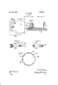
.Figure 6 is a detail longitudinal sectional view through the base'and centering guide showing a can engaged in the latter,
Figure 7 is a bottom plan view of the circular cutter,
Figure 8 is a bottom cutter,A
on the plan view of a square Figure 9 is a cross sectional view therethrough,
Figure 10 is a side elevation ,of a straight ings, the numeral 15 designates a suitable base which may be disposed at any preferred height and which may be supported by any suitable means as for instance by being secured upon a table. shelf or other support. Secured upon and rising from this base is a standard 16 which is shown as being rectangular in cross section and secured upon which standard in spaced relation to each other, are yokes 17 which are of elongated loop formation and which are riveted to the standard, as shown at 18. Slidable through these yokes is a vertically disposed bar 19 which is formed with a plurality of holes 20 for a purpose to be described. Disposed on opposite sides of the standard and pivoted thereto, as shown at 21, are links 22 with the lower ends of which are pivotally con nected levers 23 which are pivotally connected with the bar 19 by means of a suitable pin 24 passing through a selected one of the holes 20. The levers 23 are of any desired length and are to be moved to move the bar 19 up and down through the guide yokes 17.
Disposed upon the base 15 is a centering guide for properly centering the can to be opened and it will of course be understood that there must be a set of these centering guides, depending upon the shape and size of cans to be opened. Ihave shown the centering guide as formed of a suitable plate 26 having its smaller end formed with a slot 27 adapted to be slipped onto the lower end of the standard 16. For preventing upward movement of the guide I provide a U-shaped clip 28 which is disposed in straddling relation upon the lower end of the standard and y held thereon by a suitable transverse pin 29.
It will be seen that the plate 26 is easily slipped under the clip 28. This guide, or the plate 26, has Vits wider end formed with a recess corresponding to the size and shape of the can to be opened. I have illustrated the plate 26 as provided with a semiwircular recess 30 which is undercut7 as shown at CJi 31, to. provide a slight overhanging flange which will engage above the small bead B on the end of a can A. to be opened. Thisv ilange of cou-rse operates to hold the can down. Y
Secured upon the lower end of the member 19 is a cutter which can be of dili'erent sizes and shapes, depending kupon the cans to be opened. In Figure 7 I have shown this cutter as comprisingk a circular disk 32 provided centrally with a socket 33 which receives the lower end of the bar 19',4 this through and into the flange.- It'will be seen that the lower edge of this blade is formed with teeth 38 which are o'f course pointed and which have their edges sharpened.
square cans, I make use of a centering guide similar to that already described but formed with a rectangular recess instead of the semicircular rec-ess 30. I also replace'the cutter above described with a square cutter includling a square disk 39' having a. socket 40 having engagement upon the lower end'oit the bar 19 and having a rectangular' flange 41 within which is disposed and to which is secured the blade 42 which 1s square instead of circular. Y 1
Instead of making eitherI ai circular or asqua-re cut, I may make use of the cutterA shown in Figures 10 and 11. In this form* the cutter includes a blockl 43- carrying a socket 44 for engagement upon the bar, and having a longitudinaly slot 45 within' which is secured a straight blade 46. The' operation otthe device is as follows The can to be opened is placed upon the base 15, it being at first. necessary to place theproper centering guide' plate 26 in position", the selection of the guide plate depending upon the shape and diameter of vthe can to be opened. I then secure whichever cutter' it is' desired to use upon the lower end' of the bar 19 and adjust the height of the bar 19 to bring the' cutter at the desired height with respect to the can A to be cut,
it being well known that such adjustment isv necessary owing to the variations in the heights of cans. The `operator then grasps the lever 23 and presses downwardly upon it which will' of course result in downward movement of the bar 19 so as to bringl the Y binding.
cutting blade into penetrating engagement with the top ot' the can. It will be observed thatv the liange surrounding the blade extends almost to the base of the teeth and will strike against the top of the can for limiting the insertion of the ,blade beyond therdegree necessary toV effectV the cutting action. The operator then Vmoves the bar 19 upwardly whereupon the blade will be withdrawn from the can'.` In case the blade pivotally connected with these links7 it will lie-apparent that therewill be very tree move- Y. nient ot the bar 19 withoutany possibility of The operation isV of course the saine regardless ot which. shape of cutter is used olie-.cpt that when the' form'oli'thc' cutter shown in Figures 1'0 and 11 is vemployed the practice would be to make two cuts at right angles to each other in the center ot the can top. Y In case the device is to be used for cutting From the foregoing description Vand *aV study of the drawings it will be appa-rent that I have thus Vprovided'a simply conf ystructed andE consequently inexpensive can Vopener by means-oilD which al large number of cans of any size or shape may beopened in a remarkably short time, vthe device thus recommending itself for use anywhere where canned goods are used on a wholesalescale;
lVhileI have shown and described the preferred embodiment oiv my inventioinit is of course to be understoodv that I reserve the right to make such changes" in the form, construction and arrangement of parts as will? not depart from the spirit of the invention or the scope of the subjoiuned claim.
I-Iavin' claim: i
In a can opening machine, a base, an lup-` right rising therefrom and'adapted to support the cutter, and centering means for the can for properlypositioning' the" saine upon the base, comprisinga plate disposable upon the base and slotted for engagement upon the upright; said plate having' a semi-circular v rec-ess for receiving a can, the recess having its edge under cut to denne a flange overg thus described my invention, I
lying the bead at the b'ottomfof a can', and'v p Y a U-shaped clip engaged upon the upright the plate for holding the latter against up'-V Vward displacementin case of a tendency lto lift the can fro'nithe base;v
In testimony whereofI atlixmy signature.VY
DANIEL B. Boon;
and engaging against the slotted portion etno'
Priority Applications (1)
| Application Number | Priority Date | Filing Date | Title |
|---|---|---|---|
| US501609A US1521271A (en) | 1921-09-19 | 1921-09-19 | Can opener |
Applications Claiming Priority (1)
| Application Number | Priority Date | Filing Date | Title |
|---|---|---|---|
| US501609A US1521271A (en) | 1921-09-19 | 1921-09-19 | Can opener |
Publications (1)
| Publication Number | Publication Date |
|---|---|
| US1521271A true US1521271A (en) | 1924-12-30 |
Family
ID=23994271
Family Applications (1)
| Application Number | Title | Priority Date | Filing Date |
|---|---|---|---|
| US501609A Expired - Lifetime US1521271A (en) | 1921-09-19 | 1921-09-19 | Can opener |
Country Status (1)
| Country | Link |
|---|---|
| US (1) | US1521271A (en) |
Cited By (2)
| Publication number | Priority date | Publication date | Assignee | Title |
|---|---|---|---|---|
| US4092005A (en) * | 1976-09-09 | 1978-05-30 | The Raymond Lee Organization, Inc. | Vegetable chopper |
| US7409768B1 (en) * | 2005-05-09 | 2008-08-12 | Samuel Lee Chapman | Can opener |
-
1921
- 1921-09-19 US US501609A patent/US1521271A/en not_active Expired - Lifetime
Cited By (2)
| Publication number | Priority date | Publication date | Assignee | Title |
|---|---|---|---|---|
| US4092005A (en) * | 1976-09-09 | 1978-05-30 | The Raymond Lee Organization, Inc. | Vegetable chopper |
| US7409768B1 (en) * | 2005-05-09 | 2008-08-12 | Samuel Lee Chapman | Can opener |
Similar Documents
| Publication | Publication Date | Title |
|---|---|---|
| US1521271A (en) | Can opener | |
| US1284132A (en) | Apple-coring device. | |
| US2135116A (en) | Can opener | |
| US2133529A (en) | Oyster opener | |
| US2426120A (en) | Nut cracker | |
| US1604006A (en) | Can opener | |
| US2571310A (en) | Can opener | |
| US1891997A (en) | Vegetable slicer | |
| US1164776A (en) | Can-opener. | |
| US2058925A (en) | Adjustable can opener and funnel | |
| US2198613A (en) | Paper hanger's instrument | |
| US1650842A (en) | Can opener | |
| US482057A (en) | Can-opener | |
| US2984904A (en) | Can opener cutter wheel carrier assembly | |
| US1790439A (en) | Btybo patebmann | |
| US2083435A (en) | Safety wedge cutter | |
| US2265148A (en) | Can opener | |
| US1437860A (en) | Nutcracker | |
| US1182781A (en) | Can-opener. | |
| US1329133A (en) | Can-opener | |
| US1728569A (en) | Can opener | |
| US606805A (en) | Can-opener | |
| US540099A (en) | Can-opener | |
| US2240975A (en) | Envelope opener | |
| US2622317A (en) | Can opener |