US1516474A - Alfred denis - Google Patents
Alfred denis Download PDFInfo
- Publication number
- US1516474A US1516474A US1516474DA US1516474A US 1516474 A US1516474 A US 1516474A US 1516474D A US1516474D A US 1516474DA US 1516474 A US1516474 A US 1516474A
- Authority
- US
- United States
- Prior art keywords
- boiler
- casing
- flue
- extension
- furnace
- Prior art date
- Legal status (The legal status is an assumption and is not a legal conclusion. Google has not performed a legal analysis and makes no representation as to the accuracy of the status listed.)
- Expired - Lifetime
Links
Images
Classifications
-
- A—HUMAN NECESSITIES
- A47—FURNITURE; DOMESTIC ARTICLES OR APPLIANCES; COFFEE MILLS; SPICE MILLS; SUCTION CLEANERS IN GENERAL
- A47J—KITCHEN EQUIPMENT; COFFEE MILLS; SPICE MILLS; APPARATUS FOR MAKING BEVERAGES
- A47J27/00—Cooking-vessels
- A47J27/14—Cooking-vessels for use in hotels, restaurants, or canteens
- A47J27/16—Cooking-vessels for use in hotels, restaurants, or canteens heated by steam
-
- F—MECHANICAL ENGINEERING; LIGHTING; HEATING; WEAPONS; BLASTING
- F24—HEATING; RANGES; VENTILATING
- F24H—FLUID HEATERS, e.g. WATER OR AIR HEATERS, HAVING HEAT-GENERATING MEANS, e.g. HEAT PUMPS, IN GENERAL
- F24H1/00—Water heaters, e.g. boilers, continuous-flow heaters or water-storage heaters
- F24H1/06—Portable or mobile, e.g. collapsible
Definitions
- the present invention relates to improvements in a canning apparatus, and relates to that type in which the furnace is entirely surrounded by water.
- the invention contemplates an extension easing into which the furnace casing is extended, thus providing means for handling a large or small amount of water.
- the invention further resides in novel means for operating the doors which control the passage of the fuel gases into the extension chamber.
- Figure 1 is a side elevation of a device according to the invention
- Figure 2 is a top view, the cover and pans having been removed;
- FIG 3 is a cross section on line 33 of Figure 2, the pans being illustrated in section;
- Figure 4 is a modified form of the boiler cover, a portion of the boiler being shown in section.
- a boiler preferably of rectangular shape and provided with a pyramidal cover 2 on its upper open end.
- 3 indicates a furnace casing mounted in the boiler and having its bottom, top, sides and one end suitably spaced from the interior sides of said boiler, said furnace casing having an opening 4 into the forward end of the boiler and which may be closed by the door 5, the said furnace casing being preferably longitudinally disposed somewhat on one side of the center of the inside of said boiler and made to project into the extension casing 6.
- the extension casing 6 is preferably provided at one end of said boiler and is provided with a cover 7.
- the furnace casing 3 extending into said portion 6 is also suitably spaced at its bottom, top sides and end from said casing and projects at 8 beyond the width of the casing 3.
- To said extension 8 is suitably connected the horizontal and parallel flue 9 which extends from said extension 8 back into the boiler l and terminates outside of said boiler with the chimney 10.
- the flue 9 communicates with the furnace casing 3 by means of the right angular flue 11.
- the flue 11 is preferably closed by means of the sliding door 12.
- 13 is a door pivotally mounted at 14 in the bottom of the furnace casing and located at the end of the boiler 1, said doors 13 and 12 being simultaneously operated by means of the rod 15.
- the rod 15 is provided at one end with the handle 16 which projects outside of the boiler 1 and is secured at 17 to the sliding door 12, so that when the rod 15 is pushed longitudinally and inwardly the door 12 will be closed. Simultaneously the door 13 will be opened as indicated in dotted lines in Figure 3, by means of the pivoted link 18 which is connected at one end to the other end, of said rod 15, and at its other end, is pivotally connected to the door 13. By pulling said handle 16 outwardly the door 13 is operated to close a portion of said furnace casing 3 and simultaneously open the door 12, thus allowing the products of combustion to enter the flue 9 by means 01 the flue 11.
- the object of the flue 11 and the doors 12 and 13 is to heat the casing 6 simultaneously with the boiler 1 when desired, or heat only the contents of the boiler 1.
- the boiler 1 and the casing 6 are preferably filled with water.
- 19 are trays suitably disposed across the casing 23, and flue 9 in said boiler and easing 6. In said trays the canned goods are placed for cooking.
- the boiler 1 and casing G are also each provided on one side with taps 20 for emptying them of water.
- the boiler 1 has also provided at its forward end a tray 21 to prevent the ashes from falling to the ground.
- FIG 4 a modified form of cover for the boiler 1.
- the cover which is pyramidal is provided at its apex with the nipple 22 which preferably connects with the inner side of said cover and on which is mounted the hose 23.
- the object of said hose is to provide suitable means for the steam to escape from said boiler.
- a canning apparatus comprising a boiler; an extension casing secured to said boiler; a furnace casing secured in said boiler and extension casing and having bottom, side and top portions; a flue in said boiler arranged parallel to and connected to said furnace casing in the extension casing; a right-angular flue connecting said furnace casing and said first-named flue together; a door hinged to the bottom portion of said furnace casing adapted to shutoff that part of the furnace casing which projects into said extension casing; a sliding door secured to the side portion of the furnace casing and adapted to close the opening into the right angular flue; trays arranged on the top por tion of the said casings; and means for operating said doors.
- a canning apparatus comprising a boiler; an extension casing secured to said boiler; a furnace casing secured in said boiler and extension casing; a flue in said boiler arranged parallel to and connected to said furnace casing in the extension casing; a right-angular flue connecting said furnace casing and said first-named flue together; and means including a pair of doors for controlling the passage of the flue gases through the furnace casing or said extension casing.
- a canning apparatus comprising a boiler; an extension casing secured to said boiler; a furnace casing secured in said boiler and projecting into said extension casing; a flue in said boiler secured to said furnace casing; a right-angular flue connecting said furnace casing and said firstnalned flue together; and means for closing said extension casing to guide the flue gases through the right-angular flue.
- a canning apparatus comprising a boiler; an extension casing secured to said boiler; a furnace casing secured in said boiler and projecting into said extension casing; furnace casing inthe extension casing; a rightangular flue connecting said furnace casing and said first-named flue; a hinged door in said furnace casing adapted to shut off that part of said furnace casing which projects in said extension; a sliding door in said furnace casing adapted to close the right-angular flue; and means for simultaneously operating said doors to shut off the flue gases from the furnace casing extending into the extension casing and guide them through the right-angular flue.
Landscapes
- Engineering & Computer Science (AREA)
- Physics & Mathematics (AREA)
- Thermal Sciences (AREA)
- Chemical & Material Sciences (AREA)
- Combustion & Propulsion (AREA)
- Mechanical Engineering (AREA)
- General Engineering & Computer Science (AREA)
- Food Science & Technology (AREA)
- Commercial Cooking Devices (AREA)
Description
Nov 18, 1924. 1,516,474
A. DENIS CANNING APPARATUS Filed Sept. 24 1923 Patented Nov. 18, 1924.
UNITED STATES ALFRED DENIS, OF MONTREAL, QUEBEC, CANADA.
CANNING APPARATUS.
Application filed September 24, 1923. Serial No. 664,459.
To all whom. it may GOHOQWt-f Be it known that I, ALFRED DENIS, a British subject, residing at 314 Notre Dame St. east, in the city of Montreal, in the Province of Quebec, in the Dominion of Canada, have invented certain new and useful Improvements in Canning Apparatus; and I do here by declare that the following is a true, clear, and exact description of the same.
The present invention relates to improvements in a canning apparatus, and relates to that type in which the furnace is entirely surrounded by water. The invention contemplates an extension easing into which the furnace casing is extended, thus providing means for handling a large or small amount of water. The invention further resides in novel means for operating the doors which control the passage of the fuel gases into the extension chamber.
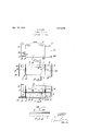
The invention is hereinafter fully described and illustrated in the accompanying drawing, in which Figure 1 is a side elevation of a device according to the invention;
Figure 2 is a top view, the cover and pans having been removed;
Figure 3 is a cross section on line 33 of Figure 2, the pans being illustrated in section; and
Figure 4 is a modified form of the boiler cover, a portion of the boiler being shown in section.
Like numerals of reference indicate corresponding parts in each figure.
Referring to the drawing 1 is a boiler preferably of rectangular shape and provided with a pyramidal cover 2 on its upper open end. 3 indicates a furnace casing mounted in the boiler and having its bottom, top, sides and one end suitably spaced from the interior sides of said boiler, said furnace casing having an opening 4 into the forward end of the boiler and which may be closed by the door 5, the said furnace casing being preferably longitudinally disposed somewhat on one side of the center of the inside of said boiler and made to project into the extension casing 6.
The extension casing 6 is preferably provided at one end of said boiler and is provided with a cover 7. The furnace casing 3 extending into said portion 6 is also suitably spaced at its bottom, top sides and end from said casing and projects at 8 beyond the width of the casing 3. To said extension 8 is suitably connected the horizontal and parallel flue 9 which extends from said extension 8 back into the boiler l and terminates outside of said boiler with the chimney 10. Approximately intermediate of its length, the flue 9 communicates with the furnace casing 3 by means of the right angular flue 11. The flue 11 is preferably closed by means of the sliding door 12. 13 is a door pivotally mounted at 14 in the bottom of the furnace casing and located at the end of the boiler 1, said doors 13 and 12 being simultaneously operated by means of the rod 15.
The rod 15 is provided at one end with the handle 16 which projects outside of the boiler 1 and is secured at 17 to the sliding door 12, so that when the rod 15 is pushed longitudinally and inwardly the door 12 will be closed. Simultaneously the door 13 will be opened as indicated in dotted lines in Figure 3, by means of the pivoted link 18 which is connected at one end to the other end, of said rod 15, and at its other end, is pivotally connected to the door 13. By pulling said handle 16 outwardly the door 13 is operated to close a portion of said furnace casing 3 and simultaneously open the door 12, thus allowing the products of combustion to enter the flue 9 by means 01 the flue 11.
The object of the flue 11 and the doors 12 and 13 is to heat the casing 6 simultaneously with the boiler 1 when desired, or heat only the contents of the boiler 1. The boiler 1 and the casing 6 are preferably filled with water. 19 are trays suitably disposed across the casing 23, and flue 9 in said boiler and easing 6. In said trays the canned goods are placed for cooking. The boiler 1 and casing G are also each provided on one side with taps 20 for emptying them of water. The boiler 1 has also provided at its forward end a tray 21 to prevent the ashes from falling to the ground.
In Figure 4 is disclosed a modified form of cover for the boiler 1. In this modified form the cover which is pyramidal is provided at its apex with the nipple 22 which preferably connects with the inner side of said cover and on which is mounted the hose 23. The object of said hose is to provide suitable means for the steam to escape from said boiler.
What I claim as my invention is 1. A canning apparatus comprising a boiler; an extension casing secured to said boiler; a furnace casing secured in said boiler and extension casing and having bottom, side and top portions; a flue in said boiler arranged parallel to and connected to said furnace casing in the extension casing; a right-angular flue connecting said furnace casing and said first-named flue together; a door hinged to the bottom portion of said furnace casing adapted to shutoff that part of the furnace casing which projects into said extension casing; a sliding door secured to the side portion of the furnace casing and adapted to close the opening into the right angular flue; trays arranged on the top por tion of the said casings; and means for operating said doors.
2. A canning apparatus comprising a boiler; an extension casing secured to said boiler; a furnace casing secured in said boiler and extension casing; a flue in said boiler arranged parallel to and connected to said furnace casing in the extension casing; a right-angular flue connecting said furnace casing and said first-named flue together; and means including a pair of doors for controlling the passage of the flue gases through the furnace casing or said extension casing.
3. A canning apparatus comprising a boiler; an extension casing secured to said boiler; a furnace casing secured in said boiler and projecting into said extension casing; a flue in said boiler secured to said furnace casing; a right-angular flue connecting said furnace casing and said firstnalned flue together; and means for closing said extension casing to guide the flue gases through the right-angular flue.
4:- A canning apparatus comprising a boiler; an extension casing secured to said boiler; a furnace casing secured in said boiler and projecting into said extension casing; furnace casing inthe extension casing; a rightangular flue connecting said furnace casing and said first-named flue; a hinged door in said furnace casing adapted to shut off that part of said furnace casing which projects in said extension; a sliding door in said furnace casing adapted to close the right-angular flue; and means for simultaneously operating said doors to shut off the flue gases from the furnace casing extending into the extension casing and guide them through the right-angular flue.
Signed at Montreal, Quebec, Canada, this 2nd day of June, 1923..
ALFRED DENIS.
'VVitnesses C. PATENAUDE; G. BEAUDOIN.
a fluein said boiler secured to said
Publications (1)
| Publication Number | Publication Date |
|---|---|
| US1516474A true US1516474A (en) | 1924-11-18 |
Family
ID=3407671
Family Applications (1)
| Application Number | Title | Priority Date | Filing Date |
|---|---|---|---|
| US1516474D Expired - Lifetime US1516474A (en) | Alfred denis |
Country Status (1)
| Country | Link |
|---|---|
| US (1) | US1516474A (en) |
-
0
- US US1516474D patent/US1516474A/en not_active Expired - Lifetime
Similar Documents
| Publication | Publication Date | Title |
|---|---|---|
| US1516474A (en) | Alfred denis | |
| US2196934A (en) | Fireplace heater | |
| US1546717A (en) | Safety cooking and baking stove | |
| US2032252A (en) | Range | |
| US1224563A (en) | Cooker. | |
| US1662747A (en) | Baker's oven | |
| US404641A (en) | Baker s oven | |
| US1596096A (en) | Smoke hood for cookstoves | |
| US987978A (en) | Stove. | |
| US1622176A (en) | Portable stove | |
| US1551619A (en) | Device | |
| US1236985A (en) | Stove. | |
| US32764A (en) | Cooking-stove | |
| US1525175A (en) | Tank heater | |
| US1747920A (en) | Combination gas range and water heater | |
| US1197677A (en) | Stove. | |
| US1149107A (en) | Stove. | |
| US731985A (en) | Hood for stoves. | |
| US2110641A (en) | althoff | |
| US944515A (en) | Heat-storing attachment for stoves. | |
| SU14575A1 (en) | Smoker for food | |
| US1308970A (en) | Combination gas and coal range | |
| US1015665A (en) | Fuel-consumer, heat-generator, and heater. | |
| US1717715A (en) | heat economizer | |
| US406204A (en) | Territory |