US1515944A - Gas heater - Google Patents
Gas heater Download PDFInfo
- Publication number
- US1515944A US1515944A US565537A US56553722A US1515944A US 1515944 A US1515944 A US 1515944A US 565537 A US565537 A US 565537A US 56553722 A US56553722 A US 56553722A US 1515944 A US1515944 A US 1515944A
- Authority
- US
- United States
- Prior art keywords
- gas heater
- gas
- mantles
- burner
- clay
- Prior art date
- Legal status (The legal status is an assumption and is not a legal conclusion. Google has not performed a legal analysis and makes no representation as to the accuracy of the status listed.)
- Expired - Lifetime
Links
- 239000004927 clay Substances 0.000 description 5
- 239000007789 gas Substances 0.000 description 5
- 238000005192 partition Methods 0.000 description 3
- 241000985696 Tecoma Species 0.000 description 2
- 238000010276 construction Methods 0.000 description 2
- 239000000446 fuel Substances 0.000 description 2
- VNWKTOKETHGBQD-UHFFFAOYSA-N methane Chemical compound C VNWKTOKETHGBQD-UHFFFAOYSA-N 0.000 description 2
- 230000015572 biosynthetic process Effects 0.000 description 1
- 238000005266 casting Methods 0.000 description 1
- 230000001276 controlling effect Effects 0.000 description 1
- 238000005336 cracking Methods 0.000 description 1
- 238000010304 firing Methods 0.000 description 1
- 238000010438 heat treatment Methods 0.000 description 1
- 238000009434 installation Methods 0.000 description 1
- 238000004519 manufacturing process Methods 0.000 description 1
- 239000000463 material Substances 0.000 description 1
- 238000000034 method Methods 0.000 description 1
- 238000000465 moulding Methods 0.000 description 1
- 239000003345 natural gas Substances 0.000 description 1
- 239000011505 plaster Substances 0.000 description 1
- 230000005855 radiation Effects 0.000 description 1
- 239000011819 refractory material Substances 0.000 description 1
- 238000004544 sputter deposition Methods 0.000 description 1
Images

Classifications
-
- F—MECHANICAL ENGINEERING; LIGHTING; HEATING; WEAPONS; BLASTING
- F24—HEATING; RANGES; VENTILATING
- F24C—DOMESTIC STOVES OR RANGES ; DETAILS OF DOMESTIC STOVES OR RANGES, OF GENERAL APPLICATION
- F24C3/00—Stoves or ranges for gaseous fuels
- F24C3/04—Stoves or ranges for gaseous fuels with heat produced wholly or partly by a radiant body, e.g. by a perforated plate
- F24C3/042—Stoves
Definitions
- This invention relates to heating devices, particularly to those employing artificial or natural gas as fuel, and has for its object the provision of a novel device in the nature of gas logs combined with a radiant portion which will operate to give oif the maximum degree of heat with the consumption of the minimum quantity of fuel.
- An important object is the provision of a combined device of this character which is constructed entirely of clay and which may be considered a practically integral structure, certain portions being treated by a more or less peculiar process whereby to insure the maximum radiation of the intense heat.
- An additional object is the provision of a device of this character which will be simple and inexpensive in manufacture, and installation, highly efiicient in use, durable in service and a general improvement in the art.
- Figure 1 is a front elevation of the device with parts broken away and in section
- Figure 2 is a vertical cross section
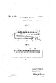
- Figure 3 is a vertical longitudinal section showing the burner structure and Figure 4 is a detail horizontal section.
- our device as comprising a body B formed of refractory material such, for instance, as clay or the like.
- This body has its lower portion wider than the upper portion and formed with chambers or hollowed portions 10 and 11. l/Vithin the upper portion is a chamber 12.
- the chambers 11 and 12 communicate with the atmosphere through holes 13 so as to avoid cracking of the body on account of increase in air pressure when it becomes hot.
- the front surface of the body, at the intermediate portion thereof, is formed flat, as indicated at 1922. Serial No. 565,537.
- rihis flat front portion constitutes the radiating element and secured thereagainst are inantles 17 formed of suitable clay and secured in place by any desired means.
- the number of mantles and air passages together with the exact formation thereof is a mere matter of design as many variations might be resorted to without in any way departing from the spirit of the invention.
- the burner structure Located within the chamber 1() is the burner structure designated broadly by the numeral 18 and including a lower conduit 19 which is connected with a casting 20 with which is associated a spud adjustment 21 cont-rolling the inlet of gas from a supply pipe 22.
- the numeral 28 designates an adjustable air shutter located within the member 2O and regulable to control the proportion of air entering the device with respect to the gas.
- the burner also includes an upper conduit 2/1 which has its top surface formed with holes 25 within which are mounted back firing preventing screens 26 and over which are disposed pressure equalizers 27 which are located below the respective mantles 17 and which really constitute the burner j ets.
- the mantles 17 are formed of wa-shed tire clay made into a heavy slip which is not too thick to be poured. Plaster Paris moldsare provided into which the slip is poured to eiect molding. After stiifening somewhat the mantles are removed from the molds, dried and then baked in the kiln.v
- the burners 18 are also formed of clay molded in a suitable form and subsequently dried and baked, though the perforations 28 in the so-called pressure equalizers are made while the burner is still somewhat plastic.
- a body formed of a mass of plastic material, and with hollow portions formed With lioles to permit the escape of air expanding under the influence of heat, a portion of the front of-said bodyv beingy formed flat and recessed7 Vertical partitions extending across the recess for defining a plurality of compartments, radiant inantles fitting Within said flat portion and closing the recess, said inantles engaging against the partitions and covering the compartments, and a burner struc ture located Within the lower portion of the body and having jets communicating with said radiant inantles.
Landscapes
- Engineering & Computer Science (AREA)
- Chemical & Material Sciences (AREA)
- Combustion & Propulsion (AREA)
- Mechanical Engineering (AREA)
- General Engineering & Computer Science (AREA)
- Helmets And Other Head Coverings (AREA)
Description
my. las WM J. T. FLOWER, JR ET AL.
. J. T. F`LOWER, JR., ET AL GAS HEATER Filed June 3, 1922 2 Sheets-Sheet 2 chmFzwerJ Parli A. Smith INVENTORS ATTORNEY W ITNESSBJ Patented Nov. 18, 1924..
JAMES T. FLOWER, JR., AND' PARK A. SMITH, 01T AKRON, OHIO.
GAS HEATER.
Application filed June 3,
To all whom it may concern:
Be it known that we, JAMES T. FLOWER, Jr., and PARK A. SMrrn, citizens of the United States, residing at Akron, in the county of Summit and State of Ohio, have invented new and useful Improvements in Gas Heaters, of which the following is a specification.
This invention relates to heating devices, particularly to those employing artificial or natural gas as fuel, and has for its object the provision of a novel device in the nature of gas logs combined with a radiant portion which will operate to give oif the maximum degree of heat with the consumption of the minimum quantity of fuel.
An important object is the provision of a combined device of this character which is constructed entirely of clay and which may be considered a practically integral structure, certain portions being treated by a more or less peculiar process whereby to insure the maximum radiation of the intense heat.
An additional object is the provision of a device of this character which will be simple and inexpensive in manufacture, and installation, highly efiicient in use, durable in service and a general improvement in the art.
Vith the above and other objects and advantages in view the invention consists in the details of construction to be hereinafter more fully described and claimed and illustrated in the accompanying drawings in which:
Figure 1 is a front elevation of the device with parts broken away and in section,
Figure 2 is a vertical cross section,
Figure 3 is a vertical longitudinal section showing the burner structure and Figure 4 is a detail horizontal section.
Referring more particularly to the drawings, we have shown our device as comprising a body B formed of refractory material such, for instance, as clay or the like. This body has its lower portion wider than the upper portion and formed with chambers or hollowed portions 10 and 11. l/Vithin the upper portion is a chamber 12. The chambers 11 and 12 communicate with the atmosphere through holes 13 so as to avoid cracking of the body on account of increase in air pressure when it becomes hot. The front surface of the body, at the intermediate portion thereof, is formed flat, as indicated at 1922. Serial No. 565,537.
14, and is provided with a series of vVertical partitions 15 defining air passages 16.
rihis flat front portion constitutes the radiating element and secured thereagainst are inantles 17 formed of suitable clay and secured in place by any desired means. The number of mantles and air passages together with the exact formation thereof is a mere matter of design as many variations might be resorted to without in any way departing from the spirit of the invention.
Located within the chamber 1() is the burner structure designated broadly by the numeral 18 and including a lower conduit 19 which is connected with a casting 20 with which is associated a spud adjustment 21 cont-rolling the inlet of gas from a supply pipe 22. The numeral 28 designates an adjustable air shutter located within the member 2O and regulable to control the proportion of air entering the device with respect to the gas. The burner also includes an upper conduit 2/1 which has its top surface formed with holes 25 within which are mounted back firing preventing screens 26 and over which are disposed pressure equalizers 27 which are located below the respective mantles 17 and which really constitute the burner j ets.
The burners 18 are also formed of clay molded in a suitable form and subsequently dried and baked, though the perforations 28 in the so-called pressure equalizers are made while the burner is still somewhat plastic.
1n the operation of the device it will be seen that the gas issuing from the jets 27 will burn and will supply an intense heat to the mantles which of course become red hot so as to be radiant for giving off great heat into the room or other place where the device is used. The air ducts or passages 16 back of the mantles prevent a suction at the base and keep the heater from making a sputtering noise while burning.
vWhile we have shown and described the preferred embodiment of the invention it is of course to be understood that we reserve the right to make such changes in the form,
construction and arrangement of parts as Will not depart from the spirit of the invention orl the soop'e o the subjoined claim.
'- Having thus described our invention We claim:
In a devieeof the eliaraoter described, a body formed of a mass of plastic material, and with hollow portions formed With lioles to permit the escape of air expanding under the influence of heat, a portion of the front of-said bodyv beingy formed flat and recessed7 Vertical partitions extending across the recess for defining a plurality of compartments, radiant inantles fitting Within said flat portion and closing the recess, said inantles engaging against the partitions and covering the compartments, and a burner struc ture located Within the lower portion of the body and having jets communicating with said radiant inantles.
In testimony whereof` we aiii; our signatures.
JAMES T. FLOVER, Ju. PARK A. SMTH.
Priority Applications (1)
| Application Number | Priority Date | Filing Date | Title |
|---|---|---|---|
| US565537A US1515944A (en) | 1922-06-03 | 1922-06-03 | Gas heater |
Applications Claiming Priority (1)
| Application Number | Priority Date | Filing Date | Title |
|---|---|---|---|
| US565537A US1515944A (en) | 1922-06-03 | 1922-06-03 | Gas heater |
Publications (1)
| Publication Number | Publication Date |
|---|---|
| US1515944A true US1515944A (en) | 1924-11-18 |
Family
ID=24259057
Family Applications (1)
| Application Number | Title | Priority Date | Filing Date |
|---|---|---|---|
| US565537A Expired - Lifetime US1515944A (en) | 1922-06-03 | 1922-06-03 | Gas heater |
Country Status (1)
| Country | Link |
|---|---|
| US (1) | US1515944A (en) |
Cited By (1)
| Publication number | Priority date | Publication date | Assignee | Title |
|---|---|---|---|---|
| DE755913C (en) * | 1934-11-04 | 1952-08-14 | Kueppersbusch & Soehne A G F | Device for roasting and roasting on a wire rack |
-
1922
- 1922-06-03 US US565537A patent/US1515944A/en not_active Expired - Lifetime
Cited By (1)
| Publication number | Priority date | Publication date | Assignee | Title |
|---|---|---|---|---|
| DE755913C (en) * | 1934-11-04 | 1952-08-14 | Kueppersbusch & Soehne A G F | Device for roasting and roasting on a wire rack |
Similar Documents
| Publication | Publication Date | Title |
|---|---|---|
| US1867110A (en) | Stove | |
| US1806216A (en) | Heater | |
| US3107720A (en) | Gas-fired radiant heaters | |
| US1515944A (en) | Gas heater | |
| US1839515A (en) | Gas burner | |
| US1280235A (en) | Stove. | |
| US1462643A (en) | Gas heater for furnaces, stoves, or apartments | |
| US1699032A (en) | Gas burner | |
| US2731010A (en) | Refractory element for gas fires and like space heating means | |
| US1903878A (en) | Heater | |
| US1415234A (en) | Floor furnace | |
| US1746546A (en) | Oil and gas burning furnace | |
| US1099876A (en) | Gas-furnace. | |
| US1698775A (en) | Gas stove | |
| US1511246A (en) | Gas burner | |
| US807244A (en) | Gas-stove. | |
| US1567830A (en) | Gas burner for heating plants | |
| US336392A (en) | converse | |
| US1383741A (en) | Gas-burner | |
| US1314860A (en) | Gas-heater tor water-backs | |
| US171481A (en) | Improvement in tobacco-curers | |
| US1286195A (en) | Drying apparatus. | |
| US1591782A (en) | Brooder heater | |
| US1432087A (en) | Combined oil and gas furnace | |
| US1383720A (en) | Low-pressure oil-burner with an attached combustion-box |