US1508564A - Gearing - Google Patents
Gearing Download PDFInfo
- Publication number
- US1508564A US1508564A US699516A US69951624A US1508564A US 1508564 A US1508564 A US 1508564A US 699516 A US699516 A US 699516A US 69951624 A US69951624 A US 69951624A US 1508564 A US1508564 A US 1508564A
- Authority
- US
- United States
- Prior art keywords
- gear
- gearing
- spur
- teeth
- concentric
- Prior art date
- Legal status (The legal status is an assumption and is not a legal conclusion. Google has not performed a legal analysis and makes no representation as to the accuracy of the status listed.)
- Expired - Lifetime
Links
Images
Classifications
-
- B—PERFORMING OPERATIONS; TRANSPORTING
- B61—RAILWAYS
- B61H—BRAKES OR OTHER RETARDING DEVICES SPECIALLY ADAPTED FOR RAIL VEHICLES; ARRANGEMENT OR DISPOSITION THEREOF IN RAIL VEHICLES
- B61H13/00—Actuating rail-vehicle brakes
- B61H13/02—Hand or other personal actuation
- B61H13/04—Hand or other personal actuation by mechanisms incorporating toothed gearing
-
- Y—GENERAL TAGGING OF NEW TECHNOLOGICAL DEVELOPMENTS; GENERAL TAGGING OF CROSS-SECTIONAL TECHNOLOGIES SPANNING OVER SEVERAL SECTIONS OF THE IPC; TECHNICAL SUBJECTS COVERED BY FORMER USPC CROSS-REFERENCE ART COLLECTIONS [XRACs] AND DIGESTS
- Y10—TECHNICAL SUBJECTS COVERED BY FORMER USPC
- Y10T—TECHNICAL SUBJECTS COVERED BY FORMER US CLASSIFICATION
- Y10T74/00—Machine element or mechanism
- Y10T74/19—Gearing
- Y10T74/1987—Rotary bodies
- Y10T74/19884—Irregular teeth and bodies
-
- Y—GENERAL TAGGING OF NEW TECHNOLOGICAL DEVELOPMENTS; GENERAL TAGGING OF CROSS-SECTIONAL TECHNOLOGIES SPANNING OVER SEVERAL SECTIONS OF THE IPC; TECHNICAL SUBJECTS COVERED BY FORMER USPC CROSS-REFERENCE ART COLLECTIONS [XRACs] AND DIGESTS
- Y10—TECHNICAL SUBJECTS COVERED BY FORMER USPC
- Y10T—TECHNICAL SUBJECTS COVERED BY FORMER US CLASSIFICATION
- Y10T74/00—Machine element or mechanism
- Y10T74/20—Control lever and linkage systems
- Y10T74/20396—Hand operated
- Y10T74/20474—Rotatable rod, shaft, or post
- Y10T74/20492—Gear
- Y10T74/20498—Variable ratio
Definitions
- the driven gear may be, initially rotated at a fast speed that i s graduso that increased; .power is obtained as the speed of the driven gear is reduced.
- One of the objects of my invention is toprovide a geanmechanism that is adapted for use in connection with the operation of the drawer rod of railroad car hand brakes .so that thewslackof Athechain'or cable may be taken vup rapidlypdndthereaiegetheratio -changesothattheleverage and power is materially increased during the 'actual braki ,ing-operation'without'altering thevspeed or power utilized at the hand-wheel. While the structure is hereindisclosed for convenience in connection with a brake mechanism, it, of course,”may be employed in connection with any structure where the principles thereof may be indicated for the services desired. In carrying out my invention I have made 'use of several types of 'gearing and have embodied the samel in two gear elements that mesh with each other in such.
- Va gearing that is extremely compact in its arrangement, that is dependable 1n operation, that is simple in construction and will not readily get out of'order
- My invention relates to gearing and more the struc- ⁇ ippiiaaoxi akanne1: 15, 1924. seran mi. esame.
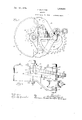
- Figure 1 is a to plan of my gear mecha ⁇ nism in assemble 'form and mounted fin a suitable retainer for use in connection with accompanying drawings that form a part of -the handoperated'bralre mechanism of :a
- FIG. 2 is avertical side elevation o the structure shown in F igure- 1.
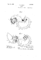
- Fi ure 3 is a top plan of the gearing illustrate in Figure 1 and with the retainer and other parts removed to disclose the relative positionfof the gear elements when vthe in itial movement begins.
- Figure 4 is'aview of the elements shown in F1gures-3 and -4r 'at an-interme'diat posi-'fi tion.
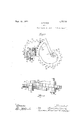
- r l g., .... Figure 6 is a side elevatio'nlof 'tlielgear ele-- -ments in the pt si'ti'c'iii shown in- Figure 5.
- a skeleton or cuen frame is secured by bolts or the like to'tne lugs 12 of the structure just described and consists of a transverse member 14 vfrom the opposite ends of which project convergingarms 15, which at their point of juncture provide a central bearing 16 for the vertical spindle 17 of the drivengear to the upper end of which the actuating hand-wheel (not shown) is secured in the usual manner.
- Extending outwardly and downwardly from the lower portion of the skeleton frame is a single arm 18, the lower end of 4which is deflected horizontally and terminates in a bearing boss 19, for the lower end of thev driven spindle 17 and is below and in alinement with thev upper bearing boss 16.
- the transverse member '14 has a downwardly extending boss 20. at about its center of length below the re-v Completed portion 1310i the top plate that-pro- ⁇ los" for the 'spindle 21 of the drive gear, an
- the drive gear preferably consists of a spur-gear 23 that forms what might be termeda hub .for said drive gear.
- the teeth of this spur-gear 23 however may not extend entirely around the same in a concentric manner but'may terminate in a block 24 so as to stop the "urther'i'otation'of the structure.
- the driving gear consists ofA a relativelysmall spur that merges into an eccentric gear that is disposed spirallyl and inclined with re- .spect to said spur and the same is mounted upon the driving spindle 21 heretofore mentioned.
- the driven element of this gearing comprises a scroll or spiral gear 'of a Vmodiiied construction and consists of a fiange or spirally inclined plate having a plurality of teeth 28 upon its edge that are adapted to mesh with the-teeth 26 of the driving-element.
- the teeth 28, of course, are s irally,-
- the flange o i' inc ined plate 27 changes its form from a convolute to a yconcentric arrangement yas ati the sector-29, but continues in an inclined plane, and the edge of this concentric portion 'is'provided vwith teeth '30 arranged concentric with the'hub or axis ofthe driven member so that the latter teeth 30 will mesh with the concentric teeth 23 which form the spilli-gear 23.
- a gearing comprising two unitary gears-in engagement with each other, a portion of the teeth on each gear being eccentric and oblique to the-axis of rotation and the remaining portion being concentric to the axis of rotation of the respective gears.
- a gearing comprising a spur gear, a convolute flange' the periphery ⁇ of which merges into said spur gear, a segmental gear adapted to engage said spur gear, and a gear element the periphery of which extends in a convolute from said segmental ear and adapted to engage the convolute ange eilt'- '3 ⁇ .”
- gearing comprising a spur gear a toothed iiange'the periphery of which un tends in a convolute from said spur gear and and" a to'qthed elemer.; the periphery of which extendsin a convolute from said segmental gear and inclined with respect there- 4.
- gearing compris-ing a spur gear, a
- segmental gear adapted tolengage said spur gear and a gear element the (periphery of whic extends in'an inwardly irection and 4in a convolute from said segmental gear and adapted to engage the ange extending from spur gear.
- a gearing comprising a spur gear, a toothed flange the periphery of which extends in amoutwardly direction and in a convolute' from said spur gear and is inclined with respect thereto, a segmental vgear adapted to mesh with' said spur ear, and a toothed element, the periphery o? which extends in an inwardly direction and in a convolute from said segmental gear and in- 'clined with respect thereto, said toothed element adapted to mesh withjthe toothed ⁇ flange extending from said spur gear.
- a gearing comprising two gear elements, each arranged obliquely vand engaged with each other, a portion of the edge of ach element being developed on a convoute.
- a gearing comprising two interengaging scroll gears disposed in planes oblique to their axes of rotation.
- a gearing comprising two gears dis- 'posedin planes oblique to their axes Aof rotation, one of saidgearsjterminating' 1n a spur pinion atl its hub that is engageable with a portion of .the other gear.
- a gearing comprising a scroll gear terminating at its outer portion in a vconcentric gear segment,'and a second scroll gearadapted to mesh with the first scroll gear and terminating at its inner end in a concentric gear segment adapted to mesh with the lirst-'mentioned concentric gear segment said scroll ears being 'arranged oblique to the axes ci; rotation.
- a gearing comprising two gear ele ments each having concentric and eccentric portions adapted to continuously interen-l gage in sequence throughout rotation and in constantly changing planes of engagement;
- a gear having concentric and eccentric portions, and a second gear the axis of which is spaced a xed distance from the axis of the first gear, said second gear shaped soas to continuously engage with said first gear and adapted to drive the same at a gradually changing speed and then at a xed ratio, said eccentric portion being arranged oblique toits axis ofrotation.
- A- gearing comprising two gear 'elements each having concentric and eccentric portions adapted to continuously interengage in sequence throughout rotation and portions of which pass 1n superposed relation during rotation.
Landscapes
- Engineering & Computer Science (AREA)
- Mechanical Engineering (AREA)
- Gears, Cams (AREA)
Description
F. MATHEWS GEARNG Filed March l5 1924 3 Shen?"afer-Shea?l l m, wm, 11508564 F. MATHEVVS GEARNG Filed March l5. 1924 3 Sheets-Sheet 2 @ng 3uh M www Sem. 16, i924@ @$508,554
F. MA1-NEWS GEARING Filed March 15. 1924 5 Sheets-Sheet 3 Panarea sept. 1e, 1924.
.rm rarnnws, or cHIcAGo, ILLINoIs.
Gemine.
' -To dll concern. 'i
.f izen of theUnited StatesVandA resident of i Chicago, in the county of Cook and State of ally diminished'as" the gear ratio changes owing to the pcc Illinois, have'invented certain new and useful Improvements in Gearin of which the following is a full, clear, an Yexact descrip- I tion, suchA as will enable others skilldinxthe art to make and use the same.
particularly to a mechanism 1n which the ratio between the ears is graduall changed,
'ar formation cry ture,.so that the driven gear may be, initially rotated at a fast speed that i s graduso that increased; .power is obtained as the speed of the driven gear is reduced.
One of the objects of my invention is toprovide a geanmechanism that is adapted for use in connection with the operation of the drawer rod of railroad car hand brakes .so that thewslackof Athechain'or cable may be taken vup rapidlypdndthereaiegetheratio -changesothattheleverage and power is materially increased during the 'actual braki ,ing-operation'without'altering thevspeed or power utilized at the hand-wheel. While the structure is hereindisclosed for convenience in connection with a brake mechanism, it, of course,"may be employed in connection with any structure where the principles thereof may be indicated for the services desired. In carrying out my invention I have made 'use of several types of 'gearing and have embodied the samel in two gear elements that mesh with each other in such.
manner that a continued rotation of -the power or driving gear will be transmitted to the' driven gear by a diiferentlal'action so that the latter gear will be actuated at several speeds and under a cha-nge -of leverage or ratio between the toothed faces of the respective elements.
It is also aobject of my invention to provide Va gearing that is extremely compact in its arrangement, that is dependable 1n operation, that is simple in construction and will not readily get out of'order, and
that is dependable 1n erforming. the func;-
tionsA for which it has en designed, .besides being economical to manufacture so that it ma be sold for a moderate price.
prefer to carryout my invention in substantially the manner hereinafter fully described and as vmore particularly pointed My invention relates to gearing and more the struc-` ippiiaaoxi akanne1: 15, 1924. seran mi. esame.
out in the claims, reference being had to the this specification, in' which, Figure 1 is a to plan of my gear mecha` nism in assemble 'form and mounted fin a suitable retainer for use in connection with accompanying drawings that form a part of -the handoperated'bralre mechanism of :a
railway car. e
' Figure 2 is avertical side elevation o the structure shown in F igure- 1. i
Fi ure 3 is a top plan of the gearing illustrate in Figure 1 and with the retainer and other parts removed to disclose the relative positionfof the gear elements when vthe in itial movement begins.
Figure 4 is'aview of the elements shown in F1gures-3 and -4r 'at an-interme'diat posi-'fi tion. r l g., ....Figure 6 is a side elevatio'nlof 'tlielgear ele-- -ments in the pt si'ti'c'iii shown in- Figure 5.
in Figure 3, showing their relative o'sitions i The drawings showfa typical or preferred embodiment of my invention, and similar reference characters have been employed to designate the same parts wherever they occur throughout the several views. -Referring first to Figures 1 vand 2 it willebe 4seen I provide a 'suitable housin consistin of a segmental shaped vertical y dispos wall 10, preferably of semi-circular contour, the upper edges of which are'connected by va top or cover 11, that has Aan irregular outer edge that provides screw-lugs 12 and a. req cessed portion 13. A skeleton or cuen frame is secured by bolts or the like to'tne lugs 12 of the structure just described and consists of a transverse member 14 vfrom the opposite ends of which project convergingarms 15, which at their point of juncture provide a central bearing 16 for the vertical spindle 17 of the drivengear to the upper end of which the actuating hand-wheel (not shown) is secured in the usual manner. Extending outwardly and downwardly from the lower portion of the skeleton frame is a single arm 18, the lower end of 4which is deflected horizontally and terminates in a bearing boss 19, for the lower end of thev driven spindle 17 and is below and in alinement with thev upper bearing boss 16. The transverse member '14 has a downwardly extending boss 20. at about its center of length below the re-v cessed portion 1310i the top plate that-pro-` los" for the 'spindle 21 of the drive gear, an
'is provided at the upper end of the arm 1.8
heretofore mentioned for the lower end of said s indle. The structure heretofore describe while it is desirable when the gearing is used in connection with a hand-brake for railway cars, is not, however, essential to the successful operation of the gearing herein disclosed, and, as any suitable means may be provided for mounting the gearing structure,`the same forms no part of my present invention.
The drive gear,.as seen in the drawings, preferably consists of a spur-gear 23 that forms what might be termeda hub .for said drive gear. The teeth of this spur-gear 23 however may not extend entirely around the same in a concentric manner but'may terminate in a block 24 so as to stop the "urther'i'otation'of the structure. Extending from the spur-gear is an inclined scrollgear in the form-of 'aneccentricjlange 25, having upon its edge a i lurality of teeth 26 so that there is provi ed' a spiral gear, that is eccentric to or.` forms a convolute around the spur-gear with its smallest radius .at the spur-gear.- Thus it will,V be seen the driving gear consists ofA a relativelysmall spur that merges into an eccentric gear that is disposed spirallyl and inclined with re- .spect to said spur and the same is mounted upon the driving spindle 21 heretofore mentioned.
The driven element of this gearing comprises a scroll or spiral gear 'of a Vmodiiied construction and consists of a fiange or spirally inclined plate having a plurality of teeth 28 upon its edge that are adapted to mesh with the-teeth 26 of the driving-element. The teeth 28, of course, are s irally,-
arranged and extend in an inclined p ane so that they will mesh with lall of the teeth 26:12u the spiral and eccentric portion of the driving f member. Part wa around its periphery, the flange o i' inc ined plate 27 changes its form from a convolute to a yconcentric arrangement yas ati the sector-29, but continues in an inclined plane, and the edge of this concentric portion 'is'provided vwith teeth '30 arranged concentric with the'hub or axis ofthe driven member so that the latter teeth 30 will mesh with the concentric teeth 23 which form the spilli-gear 23.
In its initial position, illustrated in detail in Figures 1, 2 and 3 of the drawings, the teeth 26 of the eccentric flange 25 on the driving member are in mesh with the teeth 28.on the eccentrieor scroll portion of the driven member, and when the driven member is rotated in the direction of the arrow (Figure 3), the driven member will be actuated rapidly and, in the case of a brake on a railway' car, there is little or no resistance to be overcomeand the slack in the .tending from said spur gear.
chain will be rapidly or quickly taken'np. Upon the respective gear members reaching the positions shown in Fi res 5 and 6 the slack in the chain4 or cab e will have'been entirely taken up" and the power will their begin to be apphedto the brake itself. It wil be seen that the driving member will now be employingthe spur-gear'teeth 23 inV cooperation or in mesh with the teeth 30 on the concentric portion of the driven member ing 'av relatively large gear or sector at av slower speed than initially but with increased power. This will continue until the brake has been entirely set, or the spur-gear will have reached its end or block 24, at which point further rotation of the structure -is n'ot effective or may be stopped. -It will be noted that the iianges, whenthe concentric ortion of the two members are in mesh, will e passingone above the other, and this is rendered possible b the forming of the anges in an incline andv spiral manner. It will also be seen that a complete rotation of the driven member is obtained by one and a third rotations of the'drive member.
It -is obvious that divers modiiications and refinements of the structure which has been illustrated and described ma be made without materially departing l rom the prinvciple's of my invention. y I therefore desire iii-understood that all such changes are fully contemplated as .coming within the scope of the appended claims.
What I claim is 1. A gearing comprising two unitary gears-in engagement with each other, a portion of the teeth on each gear being eccentric and oblique to the-axis of rotation and the remaining portion being concentric to the axis of rotation of the respective gears.
2. A gearing comprising a spur gear, a convolute flange' the periphery` of which merges into said spur gear, a segmental gear adapted to engage said spur gear, and a gear element the periphery of which extends in a convolute from said segmental ear and adapted to engage the convolute ange eilt'- '3`.""'A gearing comprising a spur gear a toothed iiange'the periphery of which un tends in a convolute from said spur gear and and" a to'qthed elemer.; the periphery of which extendsin a convolute from said segmental gear and inclined with respect there- 4. gearing compris-ing a spur gear, a
is? inclined with respect thereto, a segmental fgear-fadapted to mesh Y. ith said spur gear;
flange the periphery of which extends in an outwardly direction in a -convolute and at "s inner end merges into said spur gear, a
. sai
segmental gear adapted tolengage said spur gear and a gear element the (periphery of whic extends in'an inwardly irection and 4in a convolute from said segmental gear and adapted to engage the ange extending from spur gear.
5. A gearing comprising a spur gear, a toothed flange the periphery of which extends in amoutwardly direction and in a convolute' from said spur gear and is inclined with respect thereto, a segmental vgear adapted to mesh with' said spur ear, and a toothed element, the periphery o? which extends in an inwardly direction and in a convolute from said segmental gear and in- 'clined with respect thereto, said toothed element adapted to mesh withjthe toothed` flange extending from said spur gear. I
6. A gearing comprising two gear elements, each arranged obliquely vand engaged with each other, a portion of the edge of ach element being developed on a convoute.
7. A gearing comprising two interengaging scroll gears disposed in planes oblique to their axes of rotation.
8. A gearing comprising two gears dis- 'posedin planes oblique to their axes Aof rotation, one of saidgearsjterminating' 1n a spur pinion atl its hub that is engageable with a portion of .the other gear.-
9. A gearing comprising a scroll gear terminating at its outer portion in a vconcentric gear segment,'and a second scroll gearadapted to mesh with the first scroll gear and terminating at its inner end in a concentric gear segment adapted to mesh with the lirst-'mentioned concentric gear segment said scroll ears being 'arranged oblique to the axes ci; rotation.
'ranged to .interengage in constantly changing planes during rotational engagement.
12. A gearing comprising two gear ele ments each having concentric and eccentric portions adapted to continuously interen-l gage in sequence throughout rotation and in constantly changing planes of engagement;
13. In gearing, a gear having concentric and eccentric portions, and a second gear the axis of which is spaced a xed distance from the axis of the first gear, said second gear shaped soas to continuously engage with said first gear and adapted to drive the same at a gradually changing speed and then at a xed ratio, said eccentric portion being arranged oblique toits axis ofrotation.
14. A- gearing comprising two gear 'elements each having concentric and eccentric portions adapted to continuously interengage in sequence throughout rotation and portions of which pass 1n superposed relation during rotation.
Signed at Chicago, county of Cook and State of Illinois, this 5th day of March 1924.
FRED MATHEWS.
Priority Applications (1)
| Application Number | Priority Date | Filing Date | Title |
|---|---|---|---|
| US699516A US1508564A (en) | 1924-03-15 | 1924-03-15 | Gearing |
Applications Claiming Priority (1)
| Application Number | Priority Date | Filing Date | Title |
|---|---|---|---|
| US699516A US1508564A (en) | 1924-03-15 | 1924-03-15 | Gearing |
Publications (1)
| Publication Number | Publication Date |
|---|---|
| US1508564A true US1508564A (en) | 1924-09-16 |
Family
ID=24809664
Family Applications (1)
| Application Number | Title | Priority Date | Filing Date |
|---|---|---|---|
| US699516A Expired - Lifetime US1508564A (en) | 1924-03-15 | 1924-03-15 | Gearing |
Country Status (1)
| Country | Link |
|---|---|
| US (1) | US1508564A (en) |
Cited By (2)
| Publication number | Priority date | Publication date | Assignee | Title |
|---|---|---|---|---|
| US20110101752A1 (en) * | 2009-11-04 | 2011-05-05 | Elmar Deegener | Adjuster for a vehicle seat |
| CN102720825A (en) * | 2012-06-28 | 2012-10-10 | 三一重工股份有限公司 | Gear, transmission system and engineering machine |
-
1924
- 1924-03-15 US US699516A patent/US1508564A/en not_active Expired - Lifetime
Cited By (6)
| Publication number | Priority date | Publication date | Assignee | Title |
|---|---|---|---|---|
| US20110101752A1 (en) * | 2009-11-04 | 2011-05-05 | Elmar Deegener | Adjuster for a vehicle seat |
| CN102050040A (en) * | 2009-11-04 | 2011-05-11 | 凯波有限责任两合公司 | Adjusting device for vehicle seat |
| JP2011098719A (en) * | 2009-11-04 | 2011-05-19 | Keiper Gmbh & Co Kg | Adjuster for vehicle seat |
| US8616646B2 (en) * | 2009-11-04 | 2013-12-31 | Keiper Gmbh & Co. Kg | Adjuster for a vehicle seat |
| CN102050040B (en) * | 2009-11-04 | 2015-11-25 | 凯波有限责任两合公司 | For the regulating control of seat |
| CN102720825A (en) * | 2012-06-28 | 2012-10-10 | 三一重工股份有限公司 | Gear, transmission system and engineering machine |
Similar Documents
| Publication | Publication Date | Title |
|---|---|---|
| US1508564A (en) | Gearing | |
| US3448638A (en) | Reverse planetary gear | |
| US955458A (en) | Power-gearing. | |
| US1074362A (en) | Intermittent-gear mechanism. | |
| US2744416A (en) | Differential stop mechanism | |
| US1441528A (en) | Power-transmitting device | |
| US463980A (en) | Gearing for windmills | |
| US658620A (en) | Driving apparatus for motor-vehicles. | |
| US1473907A (en) | Mechanical movement | |
| US1577770A (en) | Gearing | |
| US1285408A (en) | Gearing. | |
| US1199455A (en) | Gear-wheel. | |
| US1715778A (en) | Variable-speed transmission | |
| US1027313A (en) | Reversing-gearing. | |
| US1132177A (en) | Transmission mechanism. | |
| US1517519A (en) | Power-transmission device | |
| US989426A (en) | Mechanism for transmitting motion. | |
| US1209884A (en) | Gearing. | |
| AT76507B (en) | Differential governor. | |
| US158035A (en) | Improvement in devices for transmitting motion | |
| US1249990A (en) | Spring-motor. | |
| US820933A (en) | Stroke and power changing device. | |
| US1562671A (en) | Gearing | |
| US1156132A (en) | Reversible-speed pulley. | |
| US1178702A (en) | Mechanical movement. |