US1494635A - Apparatus for balling scrap metal - Google Patents
Apparatus for balling scrap metal Download PDFInfo
- Publication number
- US1494635A US1494635A US55689122A US1494635A US 1494635 A US1494635 A US 1494635A US 55689122 A US55689122 A US 55689122A US 1494635 A US1494635 A US 1494635A
- Authority
- US
- United States
- Prior art keywords
- furnace
- balling
- flue
- wire
- carriage
- Prior art date
- Legal status (The legal status is an assumption and is not a legal conclusion. Google has not performed a legal analysis and makes no representation as to the accuracy of the status listed.)
- Expired - Lifetime
Links
- 239000003923 scrap metal Substances 0.000 title description 7
- 230000007246 mechanism Effects 0.000 description 16
- 206010022000 influenza Diseases 0.000 description 13
- 239000000446 fuel Substances 0.000 description 12
- 238000010438 heat treatment Methods 0.000 description 10
- 230000008093 supporting effect Effects 0.000 description 9
- 230000001276 controlling effect Effects 0.000 description 8
- 239000003921 oil Substances 0.000 description 8
- XEEYBQQBJWHFJM-UHFFFAOYSA-N Iron Chemical compound [Fe] XEEYBQQBJWHFJM-UHFFFAOYSA-N 0.000 description 4
- 239000012530 fluid Substances 0.000 description 4
- 239000000295 fuel oil Substances 0.000 description 3
- 239000002184 metal Substances 0.000 description 3
- 229910052751 metal Inorganic materials 0.000 description 3
- 239000011449 brick Substances 0.000 description 2
- 238000010586 diagram Methods 0.000 description 2
- 229910052742 iron Inorganic materials 0.000 description 2
- 238000004519 manufacturing process Methods 0.000 description 2
- 230000002441 reversible effect Effects 0.000 description 2
- CWYNVVGOOAEACU-UHFFFAOYSA-N Fe2+ Chemical compound [Fe+2] CWYNVVGOOAEACU-UHFFFAOYSA-N 0.000 description 1
- 229910000831 Steel Inorganic materials 0.000 description 1
- 241000625014 Vir Species 0.000 description 1
- 229910000754 Wrought iron Inorganic materials 0.000 description 1
- 239000003245 coal Substances 0.000 description 1
- 238000002485 combustion reaction Methods 0.000 description 1
- 150000001875 compounds Chemical class 0.000 description 1
- 238000010276 construction Methods 0.000 description 1
- 238000009408 flooring Methods 0.000 description 1
- 238000000034 method Methods 0.000 description 1
- 239000003208 petroleum Substances 0.000 description 1
- 230000001105 regulatory effect Effects 0.000 description 1
- 239000010959 steel Substances 0.000 description 1
- 230000001360 synchronised effect Effects 0.000 description 1
Images


Classifications
-
- C—CHEMISTRY; METALLURGY
- C21—METALLURGY OF IRON
- C21C—PROCESSING OF PIG-IRON, e.g. REFINING, MANUFACTURE OF WROUGHT-IRON OR STEEL; TREATMENT IN MOLTEN STATE OF FERROUS ALLOYS
- C21C3/00—Manufacture of wrought-iron or wrought-steel
-
- Y—GENERAL TAGGING OF NEW TECHNOLOGICAL DEVELOPMENTS; GENERAL TAGGING OF CROSS-SECTIONAL TECHNOLOGIES SPANNING OVER SEVERAL SECTIONS OF THE IPC; TECHNICAL SUBJECTS COVERED BY FORMER USPC CROSS-REFERENCE ART COLLECTIONS [XRACs] AND DIGESTS
- Y02—TECHNOLOGIES OR APPLICATIONS FOR MITIGATION OR ADAPTATION AGAINST CLIMATE CHANGE
- Y02P—CLIMATE CHANGE MITIGATION TECHNOLOGIES IN THE PRODUCTION OR PROCESSING OF GOODS
- Y02P10/00—Technologies related to metal processing
- Y02P10/20—Recycling
Definitions
- My invention relates to balling scrap as a step inthe manufacture of Wrought iron from scrap iron and steel, and4 one ⁇ of ⁇ the principal objects of the invention is to proparatus disclosed in United States patent to D. l-l. Leutz No. 1,012,872 patented Decem# ber 26, 1911 for apparatus for balling scrap metal.
- a further related object is to provide suitable apparatus for carrying out the improved balling process disclosed in my co-pending application Serial No. 549,310 filed April 3, 1922.
- the type of apparatuswth which this invention is primarily concerned comprises a rotary balling furnace having a. substantially cylindrical preheating chamber in which the charge of scrap is placed and an annular balling chamber of larger' diameter at one end of the furnace, ⁇ the furnace being arranged between spaced inlet and outlet flues in alignment therewith but capable of being turned, on a substantially vertical axis, out of alignment with said fines in order that the finished balls may be removed and the furnace re-charged.
- My present invention contemplates making thei'nlet flue movable Inl axis, ⁇ and to and from the furnace so ⁇ that the space intervening betweenthe'flue and the balling chamber is reduced to a minimum.
- the invention further provides new'and improved means for introducingthefluid fuel and superheated air into thefurnace.
- the movements of the inlet flue carrying the fuel feeding apparatus and the movements of the turn-table on which the furnace is supported are preferably effected, in'y accordance with ⁇ my present inventionfby means of electric motors,y and it is one of thel objects of the invention to provide acontrolmechanism yfor said motors whereby these movements cantake place only in their proper sequence. In this way a careless manipulation of the apparatus liable to injure or destroy it is prevented; i
- Fig. 1 is a longitudinal vertical sectional 'view/'of the apparatus.
- Fig. 2 is a longitudinal horizontal sectional view of the same showing in dotted lines the position to which the furnace is turned for removal of the ball and reception of a new charge of scrap.
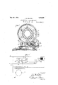
- l Fig. 3 is a view, in elevation, of the front end ofthe apparatus.
- Fig. 4 is a sectional view on line 4-4 of Fig. 1.
- Fig. 5 is a side view, in elevation, of the front end of the apparatus.
- Fig. 6 is a longitudinal sectional view of a portion of the 'oil feeding conduit.
- l Fig. 7 is a sectional view' on line 7-7 of Fig'. ⁇ 1.
- i i i Fig. 8 is a Wiring diagram to illustrate the controlof the electric motor employed for rotating the ⁇ furnace y on its 'longitudinal
- Fig. 9 is a diagram of the control mechanism for governing the synchronized movements of the turn-table supporting the fur- 'nace and thecarriage supporting the inlet flue.
- the furnace A consists of a cylindrical shell 10, providing a pre-heating chamber 11, and of an annular shell 12, of larger diameter at one end of the cylindrical shell which provides a balling chamber 13.
- the preheating and balling chambers are lined with suitable fire brick 14.
- the furnace is revolubly supported on two pairs of rollers. rfhe forward end of the furnace, that is to say, the.' balling ⁇ chamber' end, is provided with a circulartrack 15 which bears upon a pair of grooved rollers 16 carried in standards 17 secured to turntable B. Another circular track 18 is provided near the charging end of the furnace which bears on rollers 19 carried by standn ards 20 on the turn-table.
- the turn-table is provided with rollers 21 adapted to run over arcuate tracks 22 arranged on the inclined base C. n
- the furnace is rotated on its longitudinal axis by the following driving mechanism: 23 is an electric motor carried on the turntable, the armature shaft 24 of which (Figs. 2 and 7) is provided with a sprocket 25 so as to drive, by chain 26, a sprocket wheel 27 of much larger diameter on the shaft 28 and on this shaft is a small gear 29 meshing with a large gear 30 on a shaft 31 (see also Fig. 1), the latter having thereon a small gear 32 meshing with a circular rack 33 on the shell 10 of the furnace.
- the turn-table B is rotated to move the furnace into and out of alignment with the inlet and discharge fiues by means of the following mechanism: 34 is an electric motor of the reversible type (preferably with compound wound field) its armature shaft 35 carrying a sprocket 36 which drives, by chain 37, a sprocket 38 of larger diameter on a shaft 39 journalled in bearings 40 on a support 41 arranged under the forward end ofthe discharge flue G" (Figs. 1 and 2).
- Shaft 39 is provided with a worm 42 meshmg with a worm wheel 43 on a short shaft 44 journaled in the support 41 and carrying at its lower end a gear wheel 45 adapted to mesh with a sector of the turn table B.
- the inlet fiue comprises a metallic structure 47 lined vwith fire brick 48, the duct 49 therethrough aligning with the opening '50I into the balling chamber 13.
- the metallic structure is-formed with an air heating duct 51 4) having an intake 52 arranged, preferably, directl.7 above the space or crack' between the inlet flue structure D and the furnace Af so ythat the air received thereby/j gear 46 at the rear edge is heated to a certain extent before it enters the duct.
- Preferably steam is injected into the air passing through duct 51 from a nozzle 53.
- the air is drawn from duct 51 through opening 54 by a fan 55 operated by motor 55 (Figs. 3 and 4) and is injected mixed with fuel oil into the balling chamber through one or more nozzles.
- Nozzles 56, 57 are connected with the fan by a manifold 58. rlhe flow of air through the nozzles is regulated by valves 59.l 60 is an oil supply pipe (Figs. 5 and 6) extending into a casing 61 carried on a support 62 forwardly of the track F. This casing is provided with a stung boX 63 into which projects a pipe 64 clamped to a block 65 on the platform 66 of carriage E.
- This pipe eX- tends outwardly, as indicated at 67, to a manifold 68 provided with valves 69.
- Branch pipes 70, 71 provided with valves 72 extend into the air nozzles 56, 57 through stuffing boxes 73.
- the inner ends 74 of the nozzles are positioned so as to direct the jet of air and oil downwardly into the balling chamber 13.
- the mechanism for moving the carriage E to and from the furnace is as follows: 75 is an electric motor of the reversing type, the armature shaft 76 of which carries a sprocket 77 (Figs. 2 and 5) which drives, by belt 78, a sprocket wheel 79 (Fig. 3) on a shaft 80 journaled in bearings 81 on the Aplatform 66 of the carriage.
- Shaft 80 carries a small gear 82 which meshes with a large gear 83 on a shaft 84 journaled in bearings 85 under the platform 66 of the carriage.
- Shaft 84 is provided with a worm 86 meshing with a worm gear 87 on one of the wheel axles 88 of the carriage.
- the controlling mechanism for motor 23 which rotates the furnace is as follows (Fig. 8): Two or more starting buttons 89 are provided arranged in the following momentarily closed circuit: (No. 1) Wire 90, relay 91, wire 92, wire 93, wire 94 and wire 95.
- the energization of relay 91 closes a holding circuit as follows: (No. 2) From wire 92 through wire 96, stop switches 97, 97 which are normally closed. contacts 98, 98 which are closed by the switch arm 99 on the relay armature, and wire 100 to wire 95.
- the circuit through the motor is as follows: (No. 3) )Vire 101, motor armature 102, series Held 103, wire 104, switch arm 99 and wires 100 and 95.
- the motor is stopped by opening either of the stop switches 97 which are push buttons or other suitable circuit breaking devices.
- the breaking of the circuit at 97 deenergizes the relay causing it to drop its armature switch arm 99, thereby breaking the circuit through the motor.
- Mechanisms for controlling motors 75 and 34 are shown diagrammatically in Fig. 9.
- the mechanism for rcontrolling ⁇ motor 75 comprises a relay J, a set of push'buttons K and limit switches L, M and N (Figs. 5 and 9) arranged in circuits tobe hereafter described.
- the limit switches L and Mare automatically operated bythe movement of the carriage E and the limit switch N ⁇ is operated by the turn-table B.
- Themechanism for controlling the motor 34 comprises arelay O, a manually controlled switch P and automatically operated limit switches Q, R and S. ⁇
- the vlimit switches Q, and S are operated by the movement of the turntable B and the limit switch R by the flue supporting carriage E. 'The function of the above devices will be described in connection with the electric circuits Nos. 4to 13 inclusive for energizing motors 7 5 and 34.
- Circuit No.l 4 is momentarily closed through certain magnets of the relay J and is as follows: ⁇ Wircs 105, 106, circuit breaker 107, wire 108, limit switch N, operated by the turn-table B, wire 110, limit switch L, operated by the carriage E on which the inlet flue is supported, wire 112, relay magnet 113, wire 114, relay magnet 115, wire 116, momentarily closed circuit maker 107"r and wires 117 and 118.
- the energization of the relay magnets 113, 115 moves their armatures 119, 120 against contacts 121 and 122, respectively, thereby closing a ⁇ circuit (No.
- the" turn-table B may be rotated to turn furnace 105, 140, manually controlled switch l), contact 139, wire 141, contact 134limit switch R, wire 142, limit switch Q, wire 143, relay magnet 144, wire 145,1relay magnet 146, wire 147 and negative line wire 118.
- This circuit yenergize's magnets 144 and 146, so as to move their armatures against contacts 150,. 151, respectively, thereby closing a circuit (No. 8) through motor 34 as follows: l/Vires 105, 140, 152, series eld 153 of motor 34, wire 154, contact 151, relay armature 149, wire 155, motor armature 156, wire 157, relay armature 148, contact 150 and Wire 158 connected at 159'to the negative wire 147 of circuit No. 7 wWhen the furnace A reaches a predetermined position out of alignment with vthe flue, ⁇ the circuit No.7 is broken at the limit switch Q, thereby ⁇ deenergizing relay magnets 144 and 146,
- This circuit energizes magnets 165 and 167
- This circuit energizes magnets 185, 187, so 'as to move their armatures against contacts 193, 194, respectively, thereby closing a circuit (No. 12) through the motor 75 as follows: Circuit No. 5 to point 195, thence through wire 196, contact 194i, relay armature 192, wire 197 to wire 128, motor armature 127, wire 126 to relay armature 119, thence through wire 198, relay armature 191, contact 193, wires 199 and 129 to negative line wire 118.
- a holding circuit No. 13
- inlet and discharge flues the combination of inlet and discharge flues, a balling furnace between the same, means for giving angular movement to the furnace to bring it into and out of alignment with-the fiues, and means for moving the inlet fiue toward and away from the balling-furnace.
- inlet and discharge flues the combination of inlet and discharge flues, a balling furnace between the same, means for bringing the furnace into and out of alignment with the flues, means for moving the inlet flue toward and away from the balling furnace, and controllingmechanism whereby movement ofthe furnace from its operative position can be effected only after movement of the inlet flue away from the furnace and the movement of the fiue toward the furnace can be effected only when the furnace is in its operative position.
- inlet and discharge flues a balling furnace supported so that it may be turned into and out of alignment with said flues, said inlet fiue being supported so that it may move to and away from the furnace, electric motors for effecting said movements of the furnace and inlet flue, and a controlling mechanism for the motors whereby the movement of the furnace from its operative position can be effected only after movement of the flue away from the furnace and the movement of the flue4 toward the furnace can be effected only when the furnace is in its operative position.
- a stationary discharge flue an inlet Hue
- a carriage supporting the inlet iiue
- a track for the carriage in .line with the outlet flue
- a turn-table between the track and outlet flue
- a balling furnace on said turn-table adapted to align with said flues
- means which may be actuated to first move the carriage away from the furnace and means thereafter made effective to rotate theturn-table to swing the furnace out of alignment with the flues, said means being operative for. return of the parts to their operative positions only when .actuated to first rotate the turn-table to align said fines and thereafter actuated to move the carriage toward said furnace.
- a stationary discharge flue an inlet flue
- a carriage supporting the inlet flue a track for-the carriagev in line with the outlet fiue
- a turn-table between the track and outlet flue
- a balling furnace on said turn-table adapted to align with said fiues
- separate electric motors for moving said carriage on the track and rotating said turntable
- control mechanism for said motors whereby, when the turntable is rotated to swing the furnace out of alignment with the flues, the inlet flue is first moved away from the furnaceand whereby, when said parts are returned to their operative position, the turntable is first rotated to align the furnace with the fiues and the inlet fiue then moved toward the furnace.
- control mechanism for said motors whereby, when the turn-table is rotated to swing ⁇ the furnace out of alignment with the flues, the inletfiue is first moved away ⁇ from the furnace and whereby, when said parts are returned to their operative ⁇ position, the turntable is first rotated to ali n the furnace withthe iiues and the inlet ue then moved toward the furnace, said controlling mechanism comprising means whereby the movements of said carriage and turn-table out of or into their operative positions may be stopped at intermediate points, and the movement of these parts resumed in either direction.
- a balling furnace the combination of an inletflue, a carriage onl which the inlet yflue. is supported. ⁇ a track for the carriage, ⁇ a balling furnace, a turn-table on which said balling furnace is supported, and meansfor moving said carriage on said track ⁇ and for rotating said turn-table.
- a balling furnace In a balling furnace, the combination of an yinlet nue, a carriage on which the inlet flue 'is supported, atrackfor the carriapre.l a: ⁇ balling furnace, a turn-tablev on whichsaid balling furnace is supported., and means which may be actuated to first move the ⁇ carriage away from the furnace and thereafter actuated to rot-ate the turn-table to swing the furnace out of alignment with the fine, and, for return of the parts to their operative positions, is actuated to first rotate the turn-table to align the furnace with thefiue and thereafter actuated to move the carriage toward the furnace.
- ln balling apparatus the combination of a rotary furnace comprising a substantially cylindrical pre-heating chamber and an enlarged annular balling chamber at one end ofthe furnace, and a fuel oil and air nozzle arranged so as to inject oil mixed with air intosaid balling chamber.
- a rotary furnace comprising a substantially cylindrical pre-heatingfchamber and anlenlarged annular balling chamber at one end of the furnace, a fuel oil and air nozzle arranged so as to inject oil mixed ⁇ with* air into said balling chamber, and means for heatingthe air before it enters the balling chamber.
- lin balling apparatus the combination of al rotary furnace comprising a substantiallyT cylindrical preheating, chamber ⁇ and an enlarged annular balling chamber at one end of the furnace, and a pair of downwardly inclined nozzles for introducing a fluid fuel with air into the balling chamber, one of which nozzles is arranged at a higher level than the other, andr on the side thereof toward the upward ⁇ movement of the metal in the furnace produced by the rotation thereof.
- a rotary balling furnace arranged so that it may be turned to and from its operative position, a carriage movable tol and fromk the* furnace, an inlet Hue on the carriage with which said furnace is adapted to align, a fiuid fuel nozzle projecting 'into said flue, and an air heating duct surrounding ⁇ said flue and opening into the same, having an intake located adjacent the space between the flue and furnace.
- a rotary balling furnace arranged so that it may be turned to and from its operative position, a carriage movable to and from the furnace, an inlet flue on the carriage with which said furnace is adapted to align, a Huid fuel nozzle project-ing intosaid fine, an air heating duct surrounding said flue and opening into the same, and means for injecting steam into the air which passes through said duct.
- a rotary balling furnace arranged so that it may be turned to and from its operative position, a carriage movable to and from the furnace, an inlet flue on the carriage with which said furnace is adapted to align, a Huid fuel nozzle projecting into said flue, an air heating duct surrounding said flue and opening into the same, and a fan Yfor forcing the air from Said duct into the flue.
- ⁇ balling apparatus the combination of a rotary balling furnace arranged so that it may be turned to and from its operative position, a carriage movable to and from the furnace, an inlet flue on said carriage with which the furnace is adapted to align, a nozzle arranged in said fine for injecting oil mixed with air into the balling chamber', and an oil supply conduit comprising two telescopic members one stationary and the other arranged on the carriage and connecti ed with said nozzle.
Landscapes
- Engineering & Computer Science (AREA)
- Chemical & Material Sciences (AREA)
- Manufacturing & Machinery (AREA)
- Materials Engineering (AREA)
- Metallurgy (AREA)
- Organic Chemistry (AREA)
- Tunnel Furnaces (AREA)
Description
Jv. M. SELLERS APPARATUS FOR BALLING SCRAP METAL Filed April 27, 1922l e sheeis-sneet 1 J. M. SELLERS APPARATUS FOR BALLIING` SCRAP METAL May 2() 1924.
Filed April 27 .1922 s sheets-Sheet 2 f f X May 2D ,'1924. 1,494,635
u. M. SELLERS APPARATUS FOR BALLING SCRAP METAL y mea April 2*? Y1922 s sheets-sheet s May 20; 1924.
J. M. SELLERS `APPARATUS FOR BALLING SCRAP METAL Filed April v, e sheets-sheet 4 May 20 1924. 1,494,635
J. M. SELLERS APPARATUS FOR BALLING SCAP METAL Filed April 27 1922 6 Sheets-Sheet 5 May 2o, 1924e ,L Mx fig-:kwas
APFARATUS FCB @l-,LING SGBAF METAL Filed Amai.; 27. l1232:@ e sheets-sheet e I vide certain improvements in the ballingap` n r .1. L)
Patented May 20, 1924.
UNITED `S'IATES PATENT OFFICE.y
JOHN ivi. SELLERS, or :ooWNEns GROVE.' ILLINOIS; essrGNoa 'ro SELLERS MANU- FACTURING COMPANY, on CHICAGO, ILLINOIS, A CORPORATION or ILLrNors.
APPARATUS FOR BALLlfNG SCRAP Application mea `april 27, i922. sei-iai No. 556,891. y
Z 10 all 1li/1.0m t may Concern Be it known that l, JOHN M. SELLERS, a.`
new and useful Improvements in Apparatus.
for Balling Scrap Metal, of which the following is a specification. i
My invention relates to balling scrap as a step inthe manufacture of Wrought iron from scrap iron and steel, and4 one` of `the principal objects of the invention is to proparatus disclosed in United States patent to D. l-l. Leutz No. 1,012,872 patented Decem# ber 26, 1911 for apparatus for balling scrap metal. A further related object is to provide suitable apparatus for carrying out the improved balling process disclosed in my co-pending application Serial No. 549,310 filed April 3, 1922.
The type of apparatuswth which this invention is primarily concerned, that is to say, the type of apparatus exemplied in the Lentz patent just referred to, comprises a rotary balling furnace having a. substantially cylindrical preheating chamber in which the charge of scrap is placed and an annular balling chamber of larger' diameter at one end of the furnace,` the furnace being arranged between spaced inlet and outlet flues in alignment therewith but capable of being turned, on a substantially vertical axis, out of alignment with said fines in order that the finished balls may be removed and the furnace re-charged. the patented apparatus both `flue sections are stationary so that in practice it is necessary to space the fines at some little distance from the ends of the furnace, when vthe -furnace is aligned therewith, in order to give room for the turning movements' of the furnace. This is objectionable so far as the inlet flue is concerned, because it makes possible the escape from the furnace of a considerable volume of flame.` Furthermore, in the Lcntz apparatus the furnace was heated by the products of combustion of a coal fire and I have discovered that a better grade of' iron and other improved results `can be ob, tained by the use of a fluid fuel, such as petroleum oil, when properly introduced'. with superheated air and burned in or near the ballingchamber. My present invention contemplates making thei'nlet flue movable Inl axis,` and to and from the furnace so `that the space intervening betweenthe'flue and the balling chamber is reduced to a minimum.` The invention further provides new'and improved means for introducingthefluid fuel and superheated air into thefurnace. The movements of the inlet flue carrying the fuel feeding apparatus and the movements of the turn-table on which the furnace is supported are preferably effected, in'y accordance with `my present inventionfby means of electric motors,y and it is one of thel objects of the invention to provide acontrolmechanism yfor said motors whereby these movements cantake place only in their proper sequence. In this way a careless manipulation of the apparatus liable to injure or destroy it is prevented; i
IThe invention `consists in the novel and improved arrangements, constructions and devices, to be hereinafter described and claimed, for carrying out the above stated objects and such other incidental objects as will be mentioned in connection with the following description of the preferred embodiment of theinvention shown in the accompanying drawings.
In the drawings,
Fig. 1 is a longitudinal vertical sectional 'view/'of the apparatus.
Fig. 2 is a longitudinal horizontal sectional view of the same showing in dotted lines the position to which the furnace is turned for removal of the ball and reception of a new charge of scrap. l Fig. 3 is a view, in elevation, of the front end ofthe apparatus.
Fig. 4 is a sectional view on line 4-4 of Fig. 1.
Fig. 5 is a side view, in elevation, of the front end of the apparatus.
Fig. 6 is a longitudinal sectional view of a portion of the 'oil feeding conduit. l Fig. 7 is a sectional view' on line 7-7 of Fig'. `1. i i i Fig. 8 is a Wiring diagram to illustrate the controlof the electric motor employed for rotating the `furnace y on its 'longitudinal Fig. 9 is a diagram of the control mechanism for governing the synchronized movements of the turn-table supporting the fur- 'nace and thecarriage supporting the inlet flue.
Referringfto thedrawings, designates the balling furnace which is supported on a turn-table B arranged on a base or flooring C which is slightly inclined from the horizontal. D is an inlet flue supported on a carriage E running on tracks F arranged below the level of the base C. Gr is the outlet flue connected with a stack (not shown).
The furnace A consists of a cylindrical shell 10, providing a pre-heating chamber 11, and of an annular shell 12, of larger diameter at one end of the cylindrical shell which provides a balling chamber 13. The preheating and balling chambers are lined with suitable fire brick 14.
The furnace is revolubly supported on two pairs of rollers. rfhe forward end of the furnace, that is to say, the.' balling` chamber' end, is provided with a circulartrack 15 which bears upon a pair of grooved rollers 16 carried in standards 17 secured to turntable B. Another circular track 18 is provided near the charging end of the furnace which bears on rollers 19 carried by standn ards 20 on the turn-table. The turn-table is provided with rollers 21 adapted to run over arcuate tracks 22 arranged on the inclined base C. n
The furnace is rotated on its longitudinal axis by the following driving mechanism: 23 is an electric motor carried on the turntable, the armature shaft 24 of which (Figs. 2 and 7) is provided with a sprocket 25 so as to drive, by chain 26, a sprocket wheel 27 of much larger diameter on the shaft 28 and on this shaft is a small gear 29 meshing with a large gear 30 on a shaft 31 (see also Fig. 1), the latter having thereon a small gear 32 meshing with a circular rack 33 on the shell 10 of the furnace.
The turn-table B is rotated to move the furnace into and out of alignment with the inlet and discharge fiues by means of the following mechanism: 34 is an electric motor of the reversible type (preferably with compound wound field) its armature shaft 35 carrying a sprocket 36 which drives, by chain 37, a sprocket 38 of larger diameter on a shaft 39 journalled in bearings 40 on a support 41 arranged under the forward end ofthe discharge flue G" (Figs. 1 and 2). Shaft 39 is provided with a worm 42 meshmg with a worm wheel 43 on a short shaft 44 journaled in the support 41 and carrying at its lower end a gear wheel 45 adapted to mesh with a sector of the turn table B.
The inlet fiue comprises a metallic structure 47 lined vwith fire brick 48, the duct 49 therethrough aligning with the opening '50I into the balling chamber 13. The metallic structure is-formed with an air heating duct 51 4) having an intake 52 arranged, preferably, directl.7 above the space or crack' between the inlet flue structure D and the furnace Af so ythat the air received thereby/j gear 46 at the rear edge is heated to a certain extent before it enters the duct. Preferably steam is injected into the air passing through duct 51 from a nozzle 53. The air is drawn from duct 51 through opening 54 by a fan 55 operated by motor 55 (Figs. 3 and 4) and is injected mixed with fuel oil into the balling chamber through one or more nozzles. In the drawing I have shown two of these nozzles 56, 57, one being placed at a higher level than the other on account of the tendency of the ball to roll up the curved surface of the balling chamber due to rotation of the furnace. Nozzles 56, 57 are connected with the fan by a manifold 58. rlhe flow of air through the nozzles is regulated by valves 59.l 60 is an oil supply pipe (Figs. 5 and 6) extending into a casing 61 carried on a support 62 forwardly of the track F. This casing is provided with a stung boX 63 into which projects a pipe 64 clamped to a block 65 on the platform 66 of carriage E. This pipe eX- tends outwardly, as indicated at 67, to a manifold 68 provided with valves 69. Branch pipes 70, 71 provided with valves 72 extend into the air nozzles 56, 57 through stuffing boxes 73. The inner ends 74 of the nozzles are positioned so as to direct the jet of air and oil downwardly into the balling chamber 13. When the carriage E lis moved back and forth on track F oil pipe 64 slides telescopically within the casing 61.
The mechanism for moving the carriage E to and from the furnace is as follows: 75 is an electric motor of the reversing type, the armature shaft 76 of which carries a sprocket 77 (Figs. 2 and 5) which drives, by belt 78, a sprocket wheel 79 (Fig. 3) on a shaft 80 journaled in bearings 81 on the Aplatform 66 of the carriage. Shaft 80 carries a small gear 82 which meshes with a large gear 83 on a shaft 84 journaled in bearings 85 under the platform 66 of the carriage. Shaft 84 is provided with a worm 86 meshing with a worm gear 87 on one of the wheel axles 88 of the carriage.
The controlling mechanism for motor 23 which rotates the furnace is as follows (Fig. 8): Two or more starting buttons 89 are provided arranged in the following momentarily closed circuit: (No. 1) Wire 90, relay 91, wire 92, wire 93, wire 94 and wire 95. The energization of relay 91 closes a holding circuit as follows: (No. 2) From wire 92 through wire 96, stop switches 97, 97 which are normally closed. contacts 98, 98 which are closed by the switch arm 99 on the relay armature, and wire 100 to wire 95. The circuit through the motor is as follows: (No. 3) )Vire 101, motor armature 102, series Held 103, wire 104, switch arm 99 and wires 100 and 95. The motor is stopped by opening either of the stop switches 97 which are push buttons or other suitable circuit breaking devices. The breaking of the circuit at 97 deenergizes the relay causing it to drop its armature switch arm 99, thereby breaking the circuit through the motor.
Mechanisms for controlling motors 75 and 34 are shown diagrammatically in Fig. 9. The mechanism for rcontrolling `motor 75 comprises a relay J, a set of push'buttons K and limit switches L, M and N (Figs. 5 and 9) arranged in circuits tobe hereafter described. The limit switches L and Mare automatically operated bythe movement of the carriage E and the limit switch N `is operated by the turn-table B. Themechanism for controlling the motor 34 comprises arelay O, a manually controlled switch P and automatically operated limit switches Q, R and S.` The vlimit switches Q, and S are operated by the movement of the turntable B and the limit switch R by the flue supporting carriage E. 'The function of the above devices will be described in connection with the electric circuits Nos. 4to 13 inclusive for energizing motors 7 5 and 34.
This circuit yenergize's magnets 144 and 146, so as to move their armatures against contacts 150,. 151, respectively, thereby closing a circuit (No. 8) through motor 34 as follows: l/ Vires 105, 140, 152, series eld 153 of motor 34, wire 154, contact 151, relay armature 149, wire 155, motor armature 156, wire 157, relay armature 148, contact 150 and Wire 158 connected at 159'to the negative wire 147 of circuit No. 7 wWhen the furnace A reaches a predetermined position out of alignment with vthe flue, `the circuit No.7 is broken at the limit switch Q, thereby `deenergizing relay magnets 144 and 146,
sofas to permit their armatures`148 and r149 to move away from contacts 150 and'151, and thereby open the circuit through themotor 34. When the furnace A yreaches such predetermined position 'out of alignment with the iue D, the limit switch S `is moved automatically against its contact 161. The manuallycontrolled switch P may now be moved against contact 162 to close' a relay circuit (No. 9) as follows: kWires 105, 140,'manually controlled switch. P, contact 162, wire 163, limit switch S, contact 161, wire `164, relay `magnet 165, wire 166, `relay magnet 167 and wire 168, which connects at `169 with the negative wire 147 of circuit No. 7.
This circuitenergizes magnets 165 and 167,
'so as to move the relay armatures 170, 171
against contacts 172 and 17 3, to close a reversing` circuit (No. 10) through the motor 34 aslfollows: Ther wiring of circuit No. 8
to the'point indicated by reference numeral 174, thence through wire 175, relay armature 17 0, contact 17 2, wires 176, 157, motor armature 156, wire 155 to the point indicated at 177, thence through wire 178, relay armature 171, contact 173 and wire `17 9 to the point 180 at which it connects-with wire 158 of.v
circuit No. 9. f p
When the turn-table is moved toa position to bring the furnaceA into alignment withthe inlet iiue D, the liinit switch S is automatically opened, thereby opening the circuit through the relay magnets 165, 167
whereupon the armatures )1270, 171, move away fromtheir contacts 172,173, so as to open, the circuit throughk the motor 34.` In this position of the turntable the limit switches N and Q are again closed. The inlet flue structure may now be moved toward the furnace A. This is accomplished by first closing a circuit making device 107b which momentarily closes a circuit (No. 11)` through the wires of circuit No. 4 to binding post 182, thence through wire 183, contact 136, limit switch M, wire 184, relay magnet 185, wire 186, relay magnet 187, wires 188, 189, momentarily closed circuit making device 107'), wires 190, 117 and 118. This circuit energizes magnets 185, 187, so 'as to move their armatures against contacts 193, 194, respectively, thereby closing a circuit (No. 12) through the motor 75 as follows: Circuit No. 5 to point 195, thence through wire 196, contact 194i, relay armature 192, wire 197 to wire 128, motor armature 127, wire 126 to relay armature 119, thence through wire 198, relay armature 191, contact 193, wires 199 and 129 to negative line wire 118. A holding circuit (No. 13)
through relay magnets 1875, 187 is closed, as
soon as the armatures 191, 192 are moved against contacts '193, 1941. This holding circuit follows the wiring of circuit No. 11 to binding post 200, at which point it connects with the negative side of the motor circuit No. 12. When the fine structure D reaches the desired position with relation to furnace A, the limit switch M is automatically opened, thereby deenergizing megnets 185, 187 so as to permit their armatures 191, 192, to move away from their contacts 193, 194,
v to open the circuit No. 12 through the motor 75. At the time that the limit switch M is opened, the limit switch L is automatically closed 'and the limit switch R is automatically opened.
I claim:
1. In balling apparatus, the combination of inlet and discharge flues, a balling furnace between the same, means for giving angular movement to the furnace to bring it into and out of alignment with-the fiues, and means for moving the inlet fiue toward and away from the balling-furnace.
2. In balling apparatus, the combination of inlet and discharge flues, a balling furnace between the same, means for bringing the furnace into and out of alignment with the flues, means for moving the inlet flue toward and away from the balling furnace, and controllingmechanism whereby movement ofthe furnace from its operative position can be effected only after movement of the inlet flue away from the furnace and the movement of the fiue toward the furnace can be effected only when the furnace is in its operative position.
3. In balling apparatus, the combination of inlet and discharge flues, a balling furnace supported so that it may be turned into and out of alignment with said flues, said inlet fiue being supported so that it may move to and away from the furnace, electric motors for effecting said movements of the furnace and inlet flue, and a controlling mechanism for the motors whereby the movement of the furnace from its operative position can be effected only after movement of the flue away from the furnace and the movement of the flue4 toward the furnace can be effected only when the furnace is in its operative position. l v
4.-. In balling apparatus, the combination of a stationary discharge fiue, an inlet flue, a carriage supporting the inlet fine, a track for the carriage in line with theoutlet flue, a turn-table between the track and outlet Hue a balling furnace on said turn table adapted to align with said flues, and means for moving said carriage on its track'and for rotating said turn-table.
5. In balling apparatus, the combination of a stationary discharge flue, an inlet Hue, a carriage supporting the inlet iiue, a track for the carriage in .line with the outlet flue, a turn-table between the track and outlet flue, a balling furnace on said turn-table adapted to align with said flues, means which may be actuated to first move the carriage away from the furnace and means thereafter made effective to rotate theturn-table to swing the furnace out of alignment with the flues, said means being operative for. return of the parts to their operative positions only when .actuated to first rotate the turn-table to align said fines and thereafter actuated to move the carriage toward said furnace.
6. In balling apparatus, the combination of a stationary discharge flue, an inlet flue, a carriage supporting the inlet flue, a track for-the carriagev in line with the outlet fiue, a turn-table between the track and outlet flue, a balling furnace on said turn-table adapted to align with said fiues, separate electric motors for moving said carriage on the track and rotating said turntable, and control mechanism for said motors whereby, when the turntable is rotated to swing the furnace out of alignment with the flues, the inlet flue is first moved away from the furnaceand whereby, when said parts are returned to their operative position, the turntable is first rotated to align the furnace with the fiues and the inlet fiue then moved toward the furnace.
7. In balling apparatus, the combination of a stationary discharge flue, an inlet flue, a carriage supporting the inlet flue, a track for the carriage in line with the outlet flue, a turn-table between the track and outlet flue, a balling furnace onl said turn-table adapted to align with said lines, separate lwith the fines and the inlet Hue then moved ments of said carriage and turn-tableoutv of or into their operative positions may be stopped at intermediate points. y i
8. ln balling apparatus, the combination of a stationary discharge` flue, an inlet flue, a carriage support-ing the inlet flue, for the carriage in line with the outlet flue, a turn-table between the track y and outlet flue, a balling furnace on said `turn-table adapted to align with said flues, separate electric motors for moving said carriage on` the `track and rotating said turn-table, and
control mechanism for said motors whereby, when the turn-table is rotated to swing` the furnace out of alignment with the flues, the inletfiue is first moved away `from the furnace and whereby, when said parts are returned to their operative` position, the turntable is first rotated to ali n the furnace withthe iiues and the inlet ue then moved toward the furnace, said controlling mechanism comprising means whereby the movements of said carriage and turn-table out of or into their operative positions may be stopped at intermediate points, and the movement of these parts resumed in either direction.
9. ln balling apparatus, the combination of inlet and discharge flues, a balling furnace supported so that it may be turned into and out of alignment with said flue, said inlet flue being supported so that it may move to and away from the furnace, electric motors for effecting said movements of the furnace and inlet flue, and a controlling mechanism for the motors whereby the movement of the furnace from its operative position may be effected after movement of the flue away from the furnace and the movement of the flue toward the furnace may be effected after the return of the furnace to its operative position, said control mechanism comprising means whereby the movements of saidfurnace and inlet flue out of and into their operative positions may be stopped at intermediate points and themovement of said parts thereafter resumed in yeither direction.
l0. ln balling apparatus the combination of a balling furnace and an inlet flue with which said furnace normally aligns, means for swinging the furnace angularly out of and into alignment with the flue, and means for moving the flue toward and away from the furnace.
ll. ln balling apparatus, the combination of an inlet flue supported so that it may be moved forwardly and backwardly, a balling furnace supported so that it may be moved into and out of alignment with said ue, electric motors for effecting said movements of the inlet flue and furnace, and control mechanism for said motors whereby the a track` movement of. the furnacefrom its operative position may be efectedonly after movement` of the inlet flue away from the furnace and the movement of theiiue toward the furnace may be effected only when the furnace is in alignment with the flue.
l2. ln a balling furnace, the combination of an inletflue, a carriage onl which the inlet yflue. is supported.` a track for the carriage, `a balling furnace, a turn-table on which said balling furnace is supported, and meansfor moving said carriage on said track `and for rotating said turn-table.
13. In a balling furnace, the combination of an yinlet nue, a carriage on which the inlet flue 'is supported, atrackfor the carriapre.l a: `balling furnace, a turn-tablev on whichsaid balling furnace is supported., and means which may be actuated to first move the` carriage away from the furnace and thereafter actuated to rot-ate the turn-table to swing the furnace out of alignment with the fine, and, for return of the parts to their operative positions, is actuated to first rotate the turn-table to align the furnace with thefiue and thereafter actuated to move the carriage toward the furnace.
la. ln balling apparatus, the combination of a rotary furnace comprising a `substantially cylindrical pre-heating `chamber and an enlarged annular balling chamber at one end of the furnace. and meansfor introducing finely divided fuel with air directly into the balling chamber. l.
15. ln balling apparatus, the combination of a rotary furnace comprising a substantially cylindrical pre-heating chamber and an enlarged annular balling chamber at one end ofthe furnace, and a fuel oil and air nozzle arranged so as to inject oil mixed with air intosaid balling chamber.
16. ln balling apparatus, the combination of a rotary furnace comprising a substantially cylindrical pre-heatingfchamber and anlenlarged annular balling chamber at one end of the furnace, a fuel oil and air nozzle arranged so as to inject oil mixed `with* air into said balling chamber, and means for heatingthe air before it enters the balling chamber. i
17. lin balling apparatus, the combination of al rotary furnace comprising a substantiallyT cylindrical preheating, chamber `and an enlarged annular balling chamber at one end of the furnace, and a pair of downwardly inclined nozzles for introducing a fluid fuel with air into the balling chamber, one of which nozzles is arranged at a higher level than the other, andr on the side thereof toward the upward` movement of the metal in the furnace produced by the rotation thereof.
18. In balling apparatus, the combination of a rotary balling furnace arranged so that it may be turned to and from its operative position, a carriage movable to and from the furnace, an inlet flue on the carriage with which said furnace 1s adapted to align,
a fluid fuel nozzle `projecting into said flue,
and an` air heating duct surrounding said flue and opening into the same.
19. In balling apparatus, the combination of a rotary balling furnace arranged so that it may be turned to and from its operative position, a carriage movable tol and fromk the* furnace, an inlet Hue on the carriage with which said furnace is adapted to align, a fiuid fuel nozzle projecting 'into said flue, and an air heating duct surrounding `said flue and opening into the same, having an intake located adjacent the space between the flue and furnace.
20. In balling apparatus, the combination of a rotary balling furnace arranged so that it may be turned to and from its operative position, a carriage movable to and from the furnace, an inlet flue on the carriage with which said furnace is adapted to align, a Huid fuel nozzle project-ing intosaid fine, an air heating duct surrounding said flue and opening into the same, and means for injecting steam into the air which passes through said duct.
21. In balling apparatus, the combination of a rotary balling furnace arranged so that it may be turned to and from its operative position, a carriage movable to and from the furnace, an inlet flue on the carriage with which said furnace is adapted to align, a Huid fuel nozzle projecting into said flue, an air heating duct surrounding said flue and opening into the same, and a fan Yfor forcing the air from Said duct into the flue.
22.` In `balling apparatus, the combination of a rotary balling furnace arranged so that it may be turned to and from its operative position, a carriage movable to and from the furnace, an inlet flue on said carriage with which the furnace is adapted to align, a nozzle arranged in said fine for injecting oil mixed with air into the balling chamber', and an oil supply conduit comprising two telescopic members one stationary and the other arranged on the carriage and connecti ed with said nozzle.
The combination with a `balling furnace, an inlet flue with which said furnace normally aligns, means comprising a reversible electric motor for moving the furnace out of and into alignment with the flue, and means comprising ran electric motor for moving the flue away from and toward the furnace, of controlling mechanism for said first mentioned motor comprisingI a switch which is opened when the flue is moved to a predetermined position toward the furnace and is closed when said flue is moved to a predetermined position away from said furnace, whereby said first mentioned motor can be energized only when said flue is in its outer position; and controlling mechanism for said second mentioned motor comp-rising a switch which is closed when said furnace is in alignment with said fine and is opened when the furnace is out of alignment therewith, whereby said second mentioned motor can be energized only when the furnace is in alignment with the flue.
24. In balling apparatus, the combination ofa rotary balling furnace, an inlet iue with which said furnace is adapted to align, a iiuid fuel nozzle projecting into said flue, and an air heating duct ysurrounding said flue and opening into the same.
25. In balling apparatus, the combination of a rotary balling furnace, an inlet flue with which said furnace is adapted to align, a fluid fuel nozzle projecting into said Hue, and an airfheating duct surrounding said fine and opening into the same and having an intake opening arranged near the space between said rotary balling furnace and inlet flue.
26. In balling apparatus, the combination of a rotary ballingv furnace, an inlet flue with which said furnace is adapted to align, a Huid fuel nozzle projecting into said flue, an air heating duct surrounding said flue and opening into the same, and means for injecting moisture into the airy passing through said duct. l
27, In balling apparatus,`the combination of a balling furnace and an inlet flue with which said vfurnace normally aligns, means 'for swinging thev furnace angularly out of and into alignment with the fiue, and means for moving the flue toward and away from thefurnace which means is eective to move said fiue into and out of its normal operative rposition only when the, furnace is in substantially its normal operative position.v
JOHN M. SELLERS.
Priority Applications (1)
| Application Number | Priority Date | Filing Date | Title |
|---|---|---|---|
| US55689122 US1494635A (en) | 1922-04-27 | 1922-04-27 | Apparatus for balling scrap metal |
Applications Claiming Priority (1)
| Application Number | Priority Date | Filing Date | Title |
|---|---|---|---|
| US55689122 US1494635A (en) | 1922-04-27 | 1922-04-27 | Apparatus for balling scrap metal |
Publications (1)
| Publication Number | Publication Date |
|---|---|
| US1494635A true US1494635A (en) | 1924-05-20 |
Family
ID=24223253
Family Applications (1)
| Application Number | Title | Priority Date | Filing Date |
|---|---|---|---|
| US55689122 Expired - Lifetime US1494635A (en) | 1922-04-27 | 1922-04-27 | Apparatus for balling scrap metal |
Country Status (1)
| Country | Link |
|---|---|
| US (1) | US1494635A (en) |
Cited By (1)
| Publication number | Priority date | Publication date | Assignee | Title |
|---|---|---|---|---|
| US2767971A (en) * | 1951-05-26 | 1956-10-23 | Demag Ag | Rotary tilting furnace |
-
1922
- 1922-04-27 US US55689122 patent/US1494635A/en not_active Expired - Lifetime
Cited By (1)
| Publication number | Priority date | Publication date | Assignee | Title |
|---|---|---|---|---|
| US2767971A (en) * | 1951-05-26 | 1956-10-23 | Demag Ag | Rotary tilting furnace |
Similar Documents
| Publication | Publication Date | Title |
|---|---|---|
| US2539344A (en) | Air or gas cleaning apparatus | |
| US1494635A (en) | Apparatus for balling scrap metal | |
| US1914716A (en) | Copper melting furnace | |
| US1608801A (en) | Furnace-controlling mechanism | |
| CN203672127U (en) | Gallium-magnesium alloy or indium-magnesium alloy synthetic furnace | |
| CN109945646B (en) | Device and method for adding and uncovering converter cover | |
| US1993688A (en) | Apparatus for charging, discharging, and turning the material in rotary-hearth furnaces | |
| US1750813A (en) | Drying apparatus | |
| CN114061313B (en) | A kiln waste gas treatment device | |
| CN207472072U (en) | A kind of mobile dust hood | |
| US2182616A (en) | Apparatus for continuous heating and cooling of metals | |
| CN203700463U (en) | Horizontal rotary furnace for smelting noble metal | |
| US1843336A (en) | Nonoxidizing heating furnace | |
| US1606927A (en) | Method of operating open-hearth furnaces | |
| US1102382A (en) | Apparatus for manufacturing steel. | |
| US2036902A (en) | Copper refining furnace | |
| US1175629A (en) | Hot-blast-stove appliance. | |
| US2235154A (en) | Method for the reduction of metallic oxides | |
| US1400892A (en) | Process and apparatus for refining copper | |
| US858949A (en) | Blast-furnace. | |
| US1435119A (en) | Automatic hot-blast temperature-control mechanism | |
| US1663442A (en) | Liquid-fuel-burning heater | |
| US2198870A (en) | Displaceable rotary furnace | |
| US2095567A (en) | Sintering | |
| CN110701917B (en) | Smelting furnace convenient for liquid metal conveying |