US1492002A - Scale holder - Google Patents
Scale holder Download PDFInfo
- Publication number
- US1492002A US1492002A US490400A US49040021A US1492002A US 1492002 A US1492002 A US 1492002A US 490400 A US490400 A US 490400A US 49040021 A US49040021 A US 49040021A US 1492002 A US1492002 A US 1492002A
- Authority
- US
- United States
- Prior art keywords
- scale
- guideway
- supporting member
- pointer
- bolts
- Prior art date
- Legal status (The legal status is an assumption and is not a legal conclusion. Google has not performed a legal analysis and makes no representation as to the accuracy of the status listed.)
- Expired - Lifetime
Links
- 230000008093 supporting effect Effects 0.000 description 12
- 238000010276 construction Methods 0.000 description 2
- 210000003813 thumb Anatomy 0.000 description 2
- 241000287181 Sturnus vulgaris Species 0.000 description 1
- 238000005266 casting Methods 0.000 description 1
- 235000021183 entrée Nutrition 0.000 description 1
- 238000005259 measurement Methods 0.000 description 1
- 229920000136 polysorbate Polymers 0.000 description 1
- 239000012858 resilient material Substances 0.000 description 1
Images
Classifications
-
- A—HUMAN NECESSITIES
- A41—WEARING APPAREL
- A41H—APPLIANCES OR METHODS FOR MAKING CLOTHES, e.g. FOR DRESS-MAKING OR FOR TAILORING, NOT OTHERWISE PROVIDED FOR
- A41H43/00—Other methods, machines or appliances
Definitions
- Que or" the objects of the'invention is to provide a holder of such construction that the scale will be. yieldably and preferably also slidably mounted on the holder sothat the scale may be placed in any desired posi tion relative to the holder, or, if desired, scales of ditl'erent sizes and with different graduations may be interchangeably mounted on the holder. 7
- the invention contemplates providing a guideway on asubstantially vertical supporting member, the guideway' having shoulders against which one edge of the scale abuts; and a further object of the invention is to provide one or more bolts yieldingly mounted on the supporting member in such a manner that the heads of the bolts engage the opposite edge of the scale without covering any portion of the face of the scale.
- a more specific object of theinvention is to provide one or more slots in the supporting member extending substantially'at right angles to the guideway provided thereon for the scale, in which slots the bolts for holding the scale in the guideway are mounted, springs preferably being interposed between the nuts on the bolts and the supporting member, thus providing an arrangement whereby scales varying somewhat in width may be firmly held in the desired position on the supporting member.
- a further object of the invention is to provide an indicating pointer in combination with the scale so arranged that measurements may be taken on the scale from either side of the pointer, the pointer preferably being formed of resilient material and mounted in a guideway on the supporting member in parallel arrangement with the guideway for the scale.
- a .further object of the invention is to provide a vertically extending'bar mounted onthe supporting member and whichis PTO.
- Fig. 2 is aside elevational view thereof
- the sup porting member 5 is preferably formed integrally with a base plate 6 and is provided with a plurality of laterally extending lugs 7 which are formed with aligned shoulders 8 against which one edge of a vertically positioned scale 9 abuts, the shoulders 8 being formed perpendicular to the base )late 6.
- the lugs 7 are each provided with a horizo-ntally extending slot 10 and the supporting member with a similarly extending registering aperture 11 which slot and aperture are adapted to receive a bolt 12 the outer end of which is bent around substantially at right angles to form a hook portion 13 adapted to bear against the edge of the 7 scale opposite to that hearing against the shoulders 8, the other end of the bolt being 190 screw threaded for a thumb nut 14.
- the supporting member 5 and the nut 14 are recessed at 15 and 16, respectively, for the reception of a spring 17 coiled about the bolt 12 and interposed between the nut and the supporting member.
- the bolts 12 are relatively free to move toward or away from the respective shoulders 8 whereby the scale 9 may be moved to any desired position relative to the supporting member and, scales of different width, if desired, and having different gradnations, may be interchangeably mounted onv the supportingmember.
- the full face of the scale isvisible at I all times and thescale is held preciselyat,
- Thesupporting member preferably is also provided with a guideway 18 which extends substantially parallel with the guideways for the scale and which is adapted to beembraced by a resilient U-shaped member 19 provided with a pointer 20, the pointer ex tending closeftolthe' adjacent edge of the scale 9-.v
- the pointer-and scale maybe ar ranged so that the pointer will indicate the center line of the, work or object to be scaled which permits fmeasurements to be taken: on the scale. either above or below the pointer, as may be desired.
- the supportingimember is preferably provided with a vertically extending socket in its upper: end which is adapted to receive a.
- the bar 21 may be used for supportingan incandescent lamp to illuminate the scale and pointer, or it may be used for a surface gauge scriber swivel, and used as asurface gauge.
- a device'o'f the class described comprising asupporting member provided with, a
- said guidew'ay including a bearing portion against which one longitudinal edge of the scale abuts, an axially displaceable bolt posi I tioned on said member substantially at right angles to said guideway, the head of said bolt being in engagement Wlth the opposite edge of said scale, a nut on .said bolt, and
- a device of the class described comprising asupporting member provided with a guideway, a scale slidable' in said guidei'vay,
Landscapes
- Engineering & Computer Science (AREA)
- Textile Engineering (AREA)
- A Measuring Device Byusing Mechanical Method (AREA)
- Length-Measuring Instruments Using Mechanical Means (AREA)
Description
April 29, 1924. 1,492,002
. W. J. SIMANEK SCALE HOLDER filed Aug. 6. 1921 FIG. 1 FIG. 53
Eli e E 5 5: L; H, I i 20/; \l I I2,
/E:: I I0 E 8 l7 l5 7 i i i E INVENTOR,
ATTORNE Y5 PatentedApr.'29,-1924t. I entree stares earner eerie-4s.
Application filed August 6, 1921. Serial No.490,4=00.=
T 0 all whom it may concern:
Be it known that I, WVENGEL J. SIMANEK,
" ing patterns, laying out castings, and for various other uses. 7
Que or" the objects of the'invention is to provide a holder of such construction that the scale will be. yieldably and preferably also slidably mounted on the holder sothat the scale may be placed in any desired posi tion relative to the holder, or, if desired, scales of ditl'erent sizes and with different graduations may be interchangeably mounted on the holder. 7
The invention contemplates providing a guideway on asubstantially vertical supporting member, the guideway' having shoulders against which one edge of the scale abuts; and a further object of the invention is to provide one or more bolts yieldingly mounted on the supporting member in such a manner that the heads of the bolts engage the opposite edge of the scale without covering any portion of the face of the scale. 7
A more specific object of theinvention is to provide one or more slots in the supporting member extending substantially'at right angles to the guideway provided thereon for the scale, in which slots the bolts for holding the scale in the guideway are mounted, springs preferably being interposed between the nuts on the bolts and the supporting member, thus providing an arrangement whereby scales varying somewhat in width may be firmly held in the desired position on the supporting member.
A further object of the invention is to provide an indicating pointer in combination with the scale so arranged that measurements may be taken on the scale from either side of the pointer, the pointer preferably being formed of resilient material and mounted in a guideway on the supporting member in parallel arrangement with the guideway for the scale.'
l A .further object of the invention is to provide a vertically extending'bar mounted onthe supporting member and whichis PTO.
vided with a laterally extending arm rotatablev in relation thereto and which may be'used either asa support for a. lamp, or a surface gauge scriber swlvel. r
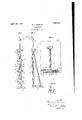
The invention consists in the novel constructions, arrangements and devices to be hereinafter describedand claimed for carrying out the above stated objects and such other objects as will appear from the fol: lowing description ofa certain preferred embodiment illustrated inithe accompanying drawings, wherein Pg. 1 is a front elevational view of a device embodying the principles of the invention;
Fig. 2is aside elevational view thereof;
Like characters of reference designate like parts in the several views.
Referring now to the drawings, the sup porting member 5 is preferably formed integrally with a base plate 6 and is provided with a plurality of laterally extending lugs 7 which are formed with aligned shoulders 8 against which one edge of a vertically positioned scale 9 abuts, the shoulders 8 being formed perpendicular to the base )late 6.
p The lugs 7 are each provided with a horizo-ntally extending slot 10 and the supporting member with a similarly extending registering aperture 11 which slot and aperture are adapted to receive a bolt 12 the outer end of which is bent around substantially at right angles to form a hook portion 13 adapted to bear against the edge of the 7 scale opposite to that hearing against the shoulders 8, the other end of the bolt being 190 screw threaded for a thumb nut 14. The supporting member 5 and the nut 14 are recessed at 15 and 16, respectively, for the reception of a spring 17 coiled about the bolt 12 and interposed between the nut and the supporting member. It will thus be seen that the bolts 12 are relatively free to move toward or away from the respective shoulders 8 whereby the scale 9 may be moved to any desired position relative to the supporting member and, scales of different width, if desired, and having different gradnations, may be interchangeably mounted onv the supportingmember. By this arrangement the full face of the scale isvisible at I all times and thescale is held preciselyat,
right angles to the base'iplate; By'means of my device and suitable calipers measure-v ments which are ordinarily diificultto ob-- tain may be conveniently and accurately-obitained. i V j Thesupporting member preferably is also provided with a guideway 18 which extends substantially parallel with the guideways for the scale and which is adapted to beembraced by a resilient U-shaped member 19 provided with a pointer 20, the pointer ex tending closeftolthe' adjacent edge of the scale 9-.v The pointer-and scale maybe ar ranged so that the pointer will indicate the center line of the, work or object to be scaled which permits fmeasurements to be taken: on the scale. either above or below the pointer, as may be desired.
The supportingimember is preferably provided with a vertically extending socket in its upper: end which is adapted to receive a.
similarlyextending rod-or bar 21, the bar being secured in the socket by means of a set screw 22. r On the upperend of the bar 21is a laterally extending arm 23 rotatably mountedon the bar and which may be secured in any'desired'position thereon by a thumb nut 24. The bar 23 may be used for supportingan incandescent lamp to illuminate the scale and pointer, or it may be used for a surface gauge scriber swivel, and used as asurface gauge.
I claim: 7 v I I 1. A device'o'f the class described comprising asupporting member provided with, a
guideway, a scale slidable in said guideway,
said guidew'ay including a bearing portion against which one longitudinal edge of the scale abuts, an axially displaceable bolt posi I tioned on said member substantially at right angles to said guideway, the head of said bolt being in engagement Wlth the opposite edge of said scale, a nut on .said bolt, and
a springv interposed between said nut and sald member for the purpose described.
2. A device of the class described comprising asupporting member provided with a guideway, a scale slidable' in said guidei'vay,
said guideway-including a bearingportion against which one longitudinal edge of the scale abuts, said member having aplurality of bolt receiving slots extending substan:
tially at right angles to said guideway, bolts in .s'aid'respective slots, the heads of said bolts being in engagement with the opposite longitudinal edge of said scale, a nut on' each for the purpose described.
In testimony whereof, I afiix my signa ture; r
wENcEL VJ. sIMANEK.
1 of said bolts,*and a spring interposed'be" tween each .ofsaid nuts and said member
Priority Applications (1)
| Application Number | Priority Date | Filing Date | Title |
|---|---|---|---|
| US490400A US1492002A (en) | 1921-08-06 | 1921-08-06 | Scale holder |
Applications Claiming Priority (1)
| Application Number | Priority Date | Filing Date | Title |
|---|---|---|---|
| US490400A US1492002A (en) | 1921-08-06 | 1921-08-06 | Scale holder |
Publications (1)
| Publication Number | Publication Date |
|---|---|
| US1492002A true US1492002A (en) | 1924-04-29 |
Family
ID=23947880
Family Applications (1)
| Application Number | Title | Priority Date | Filing Date |
|---|---|---|---|
| US490400A Expired - Lifetime US1492002A (en) | 1921-08-06 | 1921-08-06 | Scale holder |
Country Status (1)
| Country | Link |
|---|---|
| US (1) | US1492002A (en) |
Cited By (2)
| Publication number | Priority date | Publication date | Assignee | Title |
|---|---|---|---|---|
| US2546825A (en) * | 1948-06-09 | 1951-03-27 | Louis B Kravetz | Adjustable scale holding device |
| USD315107S (en) | 1987-08-05 | 1991-03-05 | Genentech, Inc. | Height measuring device |
-
1921
- 1921-08-06 US US490400A patent/US1492002A/en not_active Expired - Lifetime
Cited By (2)
| Publication number | Priority date | Publication date | Assignee | Title |
|---|---|---|---|---|
| US2546825A (en) * | 1948-06-09 | 1951-03-27 | Louis B Kravetz | Adjustable scale holding device |
| USD315107S (en) | 1987-08-05 | 1991-03-05 | Genentech, Inc. | Height measuring device |
Similar Documents
| Publication | Publication Date | Title |
|---|---|---|
| US2073089A (en) | Gauge mounting | |
| US2359018A (en) | Sine bar fixture | |
| US1551995A (en) | Device for determining angles | |
| US1492002A (en) | Scale holder | |
| US2638805A (en) | Lap vise and bench | |
| US2444727A (en) | Unitary clamp for frictionally held multiple surfaces | |
| US2614329A (en) | Protractor | |
| US3399558A (en) | Die assembly | |
| US1283795A (en) | Repair-stand. | |
| US2821022A (en) | Gage holder and scale means-attachment holder and new rules | |
| US2408651A (en) | World globe and scale | |
| US2779275A (en) | Adjustable fixture for positioning and supporting a work piece in an impact delivering machine | |
| US2670542A (en) | Adjustable height gauge | |
| US2554024A (en) | Gauge wire holder | |
| US2034350A (en) | Drafting apparatus | |
| US3021603A (en) | Gauging device | |
| US1509836A (en) | Reed-polishing machine | |
| US2497199A (en) | Gauging device | |
| US3106024A (en) | Leveling devices | |
| US1195330A (en) | binney | |
| US2567733A (en) | Drawing compass attachment | |
| US2306677A (en) | Magnetic draftsman's device | |
| US1560521A (en) | Device for gauging automobile axles | |
| US2654957A (en) | Feeler gauge | |
| US1543419A (en) | Pressure-foot attachment for clamps |