US1481237A - Means for re-forming can bodies - Google Patents
Means for re-forming can bodies Download PDFInfo
- Publication number
- US1481237A US1481237A US414845A US41484520A US1481237A US 1481237 A US1481237 A US 1481237A US 414845 A US414845 A US 414845A US 41484520 A US41484520 A US 41484520A US 1481237 A US1481237 A US 1481237A
- Authority
- US
- United States
- Prior art keywords
- flattened
- bodies
- rods
- holder
- opening
- Prior art date
- Legal status (The legal status is an assumption and is not a legal conclusion. Google has not performed a legal analysis and makes no representation as to the accuracy of the status listed.)
- Expired - Lifetime
Links
- 238000002407 reforming Methods 0.000 description 13
- 241001527902 Aratus Species 0.000 description 1
- 238000010276 construction Methods 0.000 description 1
- 230000010355 oscillation Effects 0.000 description 1
- 230000000284 resting effect Effects 0.000 description 1
- 239000011435 rock Substances 0.000 description 1
Images

Classifications
-
- B—PERFORMING OPERATIONS; TRANSPORTING
- B21—MECHANICAL METAL-WORKING WITHOUT ESSENTIALLY REMOVING MATERIAL; PUNCHING METAL
- B21D—WORKING OR PROCESSING OF SHEET METAL OR METAL TUBES, RODS OR PROFILES WITHOUT ESSENTIALLY REMOVING MATERIAL; PUNCHING METAL
- B21D1/00—Straightening, restoring form or removing local distortions of sheet metal or specific articles made therefrom; Stretching sheet metal combined with rolling
- B21D1/06—Removing local distortions
- B21D1/08—Removing local distortions of hollow bodies made from sheet metal
Definitions
- the hereinafter described invention relates to means for reforming can bodies
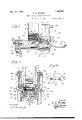
- Figure 1 is a vertical sectional view illustrating the magazine or holder for the flattened can bodies. the means for removing thelowermost can body therefrom, the openin ⁇ ; rods and horn for the can bodies, a
- F igure 2 is a broken vertical sectional view taken on the sectional lines 2-2 Figure 1 of the drawings. and viewed in the direction of the arrows. illustrating a flattened and a partially opened can body positioned within the receiving chamber therefor.
- Figure 3 is a horizontal sectional plan view taken on the sectional line 3-3, Figure 1 of the drawings, and viewed in the direction of the arrows.
- Figure 4 is a view similar to Figure 3, illustrating the opening rods and horn in their innermost'position, and within a can body to be restored.
- FIG. 5 is a vertical sectional view taken on line 5-5, Figure 3 of the drawings.
- Figure 6 is" a diagrammatic view illustrating a can body in its collapsed or flattened condition and by dotted lines illustrating the same after having been acted upon by the opening rods and horn of the apparatus.
- the numeral 1 is used to designate any suitably constructed bed plate of the apparatus, on which is mounted a superstructure 2. T 0 the superstructure 2 are secured the angle brackets 8, Fig. 2 of the drawings, which brackets support a magazine or holder 4 adapted for holding a supply of flattened can bodies 5 to be reformed when required for use.
- the said magazine or holder 4 preferably comprises two spaced vertical side plates 6, which are fastened to the angle brackets 3.
- the lower part of the magazine 4 is formed upon two sides by opposite disposed bottom plates 7, only one of which plates is illustrated in the drawings, Figure 1.
- a cylindrical horn 15 Pivotally connected at one end to the slide 10 are two spaced horizontally disposed pointed rods 14. and between and parallel to said rods. and also attached to the slide 10 is a cylindrical horn 15, formed with a flattened, two 'prongedend 16, Figs. 1, 3 and 4 of the drawings.
- a receiving or opening chamber 17 into which the flattened can bodies contained within the holder or magazine are successively transferred.
- the said receiving or opening chamber are arranged the supporting shelves 18, Figs. 1, 3 and 4 of the drawings, which shelves are adapted to receive and sustain the flattened can bodies transferred from the holder or magazine 4 into the said chamber while the said bodies are being partially re-formed by the action of the rods 14 and horn 15, as hereinafter more fully explained.
- a stop plate 20 which serves the function of limiting the movement of a flattened can body as transferred from the holder or magazine 4 into the receiving chamber and preventing the same being moved therefrom until after it has been acted upon by the rods 14 and the horn 15 to be placed in' a partially re-formed condition.
- the said plate. or stop 20 being provided with an opening 21 through which the partially reformed can is passed as carried by the horn 15 toward the re-forming mandrel 28 of the apparatus.
- a swinging pivoted arm '22 On each side of the receiving chamber 17, Fig. 2 of the drawings, there is arranged a swinging pivoted arm '22, each at its lower endbeing provided with an inwardly extended section 23, which passes or works through openings 24 provided in the side walls of the receiving chamber 17 and the innermost extremity of the inwardly projecting portion 23 of the swinging arms terminates in an angular seat or support 25, onto which the flattened can bodies 5 are received as first moved into the receiving chamber 17, the angular seat 25 of the arms 22 being situated in a plane slightly above that of the supporting shelves 18 within the said receiving chamber 17.
- Each swinging arm 22 is secured to a longitudinally dis posed rock shaft 26, which shafts are operated by any suitable mechanism for imparting rocking motion thereto for swinging the arms 22 inwardly and outwardly relative to the receiving chamber 17.
- each swinging arm 22 is further provided with a notched section 27, whiclrnotched portion is substantially in horizontal alignment with the supporting shelves 18 of the'chamher 17 when the said arms are swung inwardly their full distance, and said notched portions 27 are adapted to embrace the longitudinal edges of the flattened can body 5 on the same be.
- a mandrel 28 to which the partially re-formed can body 5' is delivered by the pusher rods 29, which rods are secured to and carried by the reciprocating slide 10.
- the opening rods 14 associated with t e horn 15, and which are employed foriniti ly engaging the flattened can body when the same rests upon the supporting shelves 18, are pivoted at their rear extremity to the slide 10 and the same are held normally outwardly pressed by means of the springs 30, Figs. 4 and 5 of the drawings, so that the normal position of the said rods is a divergent one.
- the inward or outward movement of the said pivoted or swinging rods 14,- is controlled by the adjusting screws 31.
- the opening rods 14 By means of pivotally and adjustably mounting the opening rods 14 relative to the slide 10, the same are adapted to move into a flattened can body at points adjacent the longitudinal curved edges thereof, and this irrespective as to whether the can body is slightly distorted or not and thereby insures the said rods at all times moving within the said body.
- pivoted opening rods associated with and projected beyond said means for initially engaging the interior wall of a flattened can bo y and springs pressing said rods apart.
- pivoted spring-held opening rods associated with and projected beyond said means for initially engaging the interior wall of a flattened can body, and adjusting means for limiting the swinging movement of the opening rods.
- the combination with a mandrel for receiving partly reformed can bodies of a holder adapted to contain a stack of flattened can bodies to be reformed, a chamber for receiving flattened bodies from said holder associated reciprocating means for successively removing the lowermost flattened can body from a stack contained within the holder and transferring the same to the receiving chamber, enlarging the interior dimension of said removed flattened body while contained within the receiving chamber and transferring the same to the mandrel for restoring to substantially original form.
- pivotally mounted opening rods carried by said means for initially engaging the inner wall of the flattened can body prior to having its interior dimension enlarged, and stripping means arranged in advance of the receiving chamber for removing a can body from its enlarging means prior to the discharge of the same from said chamber.
Landscapes
- Engineering & Computer Science (AREA)
- Mechanical Engineering (AREA)
- Treatment Of Fiber Materials (AREA)
Description
fan. 15 1924.
S. E. WALKER MEANS FOR RE-FORMING CAN BODIES Filed Oct. 5, 1920 2 Sheets-Sheet 1 WITNESS.
INVENTOR.
1 V 7km fiATTORNEY.
Jan. 15 1924. 1,481,237
- S. E. WALKER MEANS FOR RIB-FORMING CAN BODIES Filed Oct. 5, 1920 2 Sheets-Sheet 2 I INVENTOR. S E,
WITNESS. F
mam z 11 T BY mil/aw Patented Jan. 15, 1924.
UNITED, [STATES SELAH E. WALKER, OF WRANGELL, TERRITORY OF ALASKA.
MEANS FOR IKE-FORMING CAN' IBODIES Application filed October 5, 1920. Serial No. 414,845.
To all whom it may concern:
Be it known that I, SELAH E. WALKER, a citizen of the United States, residing at \Vrangell, Territory of Alaska, have invented certain new and useful Improvements in Means for Re-Forming Can Bodies, of which the following is a specification.
The hereinafter described invention relates to means for reforming can bodies,
more particularly for restoring such can bodies to their original cylindrical shape after they have been flattened as for shipment and storage; theinvention being an improvement on the apparatus for re-forming can bodies set forth and described in United States Letters Patent No. 1,306,810,
granted to James A. Gray under date of June 17th, 1919, and the same relates essentially to improvement in the means shown 20 in said Letters Patent for preliminary opening the flattened can body prior to the introduction therein of the horn for partially restoring or positioning the flattened can body to be received on to the mandrel upon which the said can body is trued to substantially its original form.
To comprehend the invention, reference should be had tothe accompanying sheets of drawings, wherein- Figure 1 isa vertical sectional view illustrating the magazine or holder for the flattened can bodies. the means for removing thelowermost can body therefrom, the openin}; rods and horn for the can bodies, a
positioned mandrel to receive an open can body. and the receiving chamber into which the flattened can bodies are delivered from the magazine or holder for the opening thereof prior to being positioned onto the forming mandrel.
Figure 3 is a horizontal sectional plan view taken on the sectional line 3-3, Figure 1 of the drawings, and viewed in the direction of the arrows.
Figure 4 is a view similar to Figure 3, illustrating the opening rods and horn in their innermost'position, and within a can body to be restored.
Figure 5 is a vertical sectional view taken on line 5-5, Figure 3 of the drawings.
Figure 6 is" a diagrammatic view illustrating a can body in its collapsed or flattened condition and by dotted lines illustrating the same after having been acted upon by the opening rods and horn of the apparatus.
In the drawings, the numeral 1 is used to designate any suitably constructed bed plate of the apparatus, on which is mounted a superstructure 2. T 0 the superstructure 2 are secured the angle brackets 8, Fig. 2 of the drawings, which brackets support a magazine or holder 4 adapted for holding a supply of flattened can bodies 5 to be reformed when required for use. The said magazine or holder 4 preferably comprises two spaced vertical side plates 6, which are fastened to the angle brackets 3. The lower part of the magazine 4 is formed upon two sides by opposite disposed bottom plates 7, only one of which plates is illustrated in the drawings, Figure 1. These plates serve as a support for the stack of flattened can bodies and each of said plates is provided with an inwardly projecting, flan eupon which the lowermost flattened can ody of the stack within the holder 4 rests. Immediately beneath the holder or magazine for the flattened can ends is situated a horizontally disposed guide plate 8, in the gu-ideways 9 of which is carried a reciprocating slide member 10, Figs. 1. 2 and 5 of the drawings. Horizontally reciprocating motion may be imparted to the said slide 10 by any convenient means. shown in Figs. 1 and 2 as consisting of a lug-.11 on the underside of the said slide and a lever 12 connected to said lug by a link 13, it being understood that the lever 12 is actuated by any suitable form of mechanism. preferably that shown and described in the said Letters Patent #1306810. granted to James A. Gray under date of June 17th, 1912).
Pivotally connected at one end to the slide 10 are two spaced horizontally disposed pointed rods 14. and between and parallel to said rods. and also attached to the slide 10 is a cylindrical horn 15, formed with a flattened, two 'prongedend 16, Figs. 1, 3 and 4 of the drawings.
In advance of the holder or magazine 4, there is positioned and supported. by the bed plate 1 a receiving or opening chamber 17, into which the flattened can bodies contained within the holder or magazine are successively transferred. 'ithin the said receiving or opening chamber are arranged the supporting shelves 18, Figs. 1, 3 and 4 of the drawings, which shelves are adapted to receive and sustain the flattened can bodies transferred from the holder or magazine 4 into the said chamber while the said bodies are being partially re-formed by the action of the rods 14 and horn 15, as hereinafter more fully explained. There is interposed between the receiving chamber 17 and the holder or magazine 4 a stripper plate 19, and through openings provided therein the rods 14 and horn 15 are adapted to work. To the face of the receiving chamber 17 opposite to that carrying the stripper plater 19 is attached a stop plate 20, which serves the function of limiting the movement of a flattened can body as transferred from the holder or magazine 4 into the receiving chamber and preventing the same being moved therefrom until after it has been acted upon by the rods 14 and the horn 15 to be placed in' a partially re-formed condition. the said plate. or stop 20 being provided with an opening 21 through which the partially reformed can is passed as carried by the horn 15 toward the re-forming mandrel 28 of the apparatus.
On each side of the receiving chamber 17, Fig. 2 of the drawings, there is arranged a swinging pivoted arm '22, each at its lower endbeing provided with an inwardly extended section 23, which passes or works through openings 24 provided in the side walls of the receiving chamber 17 and the innermost extremity of the inwardly projecting portion 23 of the swinging arms terminates in an angular seat or support 25, onto which the flattened can bodies 5 are received as first moved into the receiving chamber 17, the angular seat 25 of the arms 22 being situated in a plane slightly above that of the supporting shelves 18 within the said receiving chamber 17. Each swinging arm 22 is secured to a longitudinally dis posed rock shaft 26, which shafts are operated by any suitable mechanism for imparting rocking motion thereto for swinging the arms 22 inwardly and outwardly relative to the receiving chamber 17.
The inner free end of each swinging arm 22 is further provided with a notched section 27, whiclrnotched portion is substantially in horizontal alignment with the supporting shelves 18 of the'chamher 17 when the said arms are swung inwardly their full distance, and said notched portions 27 are adapted to embrace the longitudinal edges of the flattened can body 5 on the same be. ing dropped from the angular brackets 25 of the swinging arms 22 onto the supporting shelves 18- of the receiving chamber and to compress the same as the arms 22 swing in 'wardly their full distance, thereby holding the can body in this position while the same is being acted on by the opening rods 14 and horn 1 5 for the partial opening thereof or the placing of the same into the shape of the lowermost can body 5 within the chamber 17 as disclosed in Fig, 2 of the drawmgs.
Outside of the sphere of the receiving chamber 17, there is illustrated in connection with Fig. 1 of the drawings, a mandrel 28, to which the partially re-formed can body 5' is delivered by the pusher rods 29, which rods are secured to and carried by the reciprocating slide 10.
The opening rods 14 associated with t e horn 15, and which are employed foriniti ly engaging the flattened can body when the same rests upon the supporting shelves 18, are pivoted at their rear extremity to the slide 10 and the same are held normally outwardly pressed by means of the springs 30, Figs. 4 and 5 of the drawings, so that the normal position of the said rods is a divergent one. The inward or outward movement of the said pivoted or swinging rods 14,- is controlled by the adjusting screws 31. By means of pivotally and adjustably mounting the opening rods 14 relative to the slide 10, the same are adapted to move into a flattened can body at points adjacent the longitudinal curved edges thereof, and this irrespective as to whether the can body is slightly distorted or not and thereby insures the said rods at all times moving within the said body.
By the employment of these spring-held opening rods 14, much greater latitude for the entry of their free ends into a distorted body is provided than where the said rods are mounted relative to the reciprocating slide against inde endent movement, as they are illustrated and described in the said Letters Patent No. 1,306,810 of June 17th, 1919, and they serve the purpose of preventing spoilage of can bodies which is liable to occur Where the same are placed within the body holder or magazine in a distorted condition, and therefore by the use of these spring-held adjustable opening rods 14 employed in association with the horn 15, it is permissible to successively operate the reforming apparatus where the flattened can bodies are so distorted, or in other words, tliere is greater latitude permitted relative to the successful re-forming of can flattened bodies than where the opening rods are fixed and irrespective as to the condition in which the can bodies are delivered flattened into the holderfrom which they are fed for reforming.
For a full understanding of the importance and operation of the re-formingapparatus, reference slioul be had to said slide 10, the stripper plate 19 partially United States Letters Patent No. 1,306,810 of June 17th, 1919, to which reference is herewith specifically made, but briefly stated, the operation is as follows On an inward strokeof the longitudL nally reciprocating slide 10, the lowermost can body of the stack of can bodies contained within the holder or magazine. 4 is removed therefrom by means of the notched fingers 32, which are attached to the slide above the opening rods 14, Figs. 1 and 3 of the drawings. The notched ends of these fingers en body 5 o the stack within the holder or magazine and cut or separate the same from thee-said stack, and carrying the said body inwardly deposit the same onto the angular seat 25 of the swinging arms 22. As the reciprocating slide 10 makes its return stroke, the shafts 26 for the swinging arms 22 are given a part rotation or oscillation to throw outwardly the said arms 22 to release the flattened can body 5 within the re ceiving chamber, which" permits the same,
lowering onto the supportingledges or shelves 18 located wt 'in the receiving chamber 17. On the next inward stroke of the slide 10, the inner or pointed ends of the divergent swingin rods 14 move within the flattened can od graduall converging until' the said ro s areparal el, the pressure of the rods against the inner wall surface of the flattened can body partially opening the same so as to permit the forked end of the horn 15 to enter therein, which as moved inwardly within the flattened can body gradually expands the body into the position noted by dotted lines in Fig. 6 of the drawings, as the slide completes its full inward stroke. On the return stroke of the removes the partially re-formed can from ofi the horn 15, and inasmuch as t e can body at such time is of less width than the width of the flattened can body initially received into the receiving chamber 17, the same clears the supporting shelves 18 and drops intothe position of therpartially reformed can body 5', Fig. 2 of the drawings, and in which position it stands or rests in axial alignment with the mandrel 28. As the slide 10 makes its next inward stroke, the ends of the pusher rods 29 carried thereby engage the edge of the partially re-formed can body and move the same on to the mandrel 8;. it being understood that with each inward stroke of the slide 10, a flattened can body is removed from the magazine or holder 4 and transferred therefrom into the receiving chamber 17, and also a reformed body is moved on to the horn 28; and that on each outward stroke or return stroke of the said slide a flattened can bodv at the bottom of. the stack drops into line with the fingers 32 age the lowermost flattened can and a flattened can body 5 within the said chamber 17 is dropped or lowered onto the shelves 18 and a partially formed body is stripped from the horn 15.
It will be understood that the various described parts work in timed relation and that after a flattened can body has been received onto the angular-seats of the swinging arms 22, the same lowers therefrom onto the supporting shelves 18 within the receiving chamber" as the said arms swing outward. On the inward movement of the swinging arms 22, the flattened can body resting on the said shelves is slightl com ressed between the notched portions 27 of t e said arms, which partially separates or opens the body to permit the entrance of the opening rods 14 therein.
While I have shown the invention in its preferred embodiment, I do not wish to be understood as limiting or confining the same to the detailed construction of the working parts shown and described, but on the contrary wish to be understood as claiming broadly the association with the can body expanding horn of the spring held opening rods for engaging the flattened can body for opening the same to permit the entrance, of the reduced entering thereim Having thus described my invention, what I claim as new and desire to protect by Letters Patent is:-
1. In "an ap aratus for the described purpose, the com ination with a reciprocating cm for spreading deformed can bodies prior to the reforming thereof, of opening rods connectedwith and pivotally mounted relative to said horn and means for pressing said rods away from each other.
2. In an apparatus for reforming flattened cln bodies, the combination with reciprocat ing means for enlargin sion of a flattened can Eody prior to the reforming thereof to substantially original form, of o ening rods associated with said means, an devices for adjusting the position of the opening rods sidewise and relative to the edges of a flattened can body.
3. In an apparatus for reforming flattenedcan bodies, the combination with reciprocating means for enlarging the interior dimension of a flattened can body prior to the reforming thereof to substantially original form, of opening rods pivotally mounted relative to said means, means for pressing said rods away from each other and devices for adjusting the swinging movement of said rods.
4. n an apparatus for the described purpose, the combination with a mandrel for receiving enlarged flattened can bodies, of reciprocating means for enlarging the interior dimension of flattened can bodies prior to the delivery thereof onto said horn,
end 16 of the horn the interior dimen- &
pivoted opening rods associated with and projected beyond said means for initially engaging the interior wall of a flattened can bo y and springs pressing said rods apart.
5. In an apparatus for the described purpose, the combination with a mandrel for receiving enlarged flattened can bodies, of reciprocating means for enlarging the interior dimension of flattened can bodies prior to the delivery thereof onto said mandrel. pivoted spring-held opening rods associated with and projected beyond said means for initially engaging the interior wall of a flattened can body, and adjusting means for limiting the swinging movement of the opening rods.
6. In an apparatus for the described pur- "pose, the combination with means for enlarging the interior diameter of a flattened can body prior to the reforming thereof, of opening rods associated with said means and swinging' sidewise towards and from each other for initially engaging the interior wall of a flattened can body.
7. In an apparatus for the described purpose, the combination with means for enlarging the interior diameter of a flattened can body prior to the reforming thereof, of horizontally swinging opening rods asso ciated with said means for initially engaging the interior wall of a flattened can body, and adjustable means for limiting the swinging movement of the said opening rods.
8. In an apparatus for the described purpose, the combination with a holder adapted to contain a stack of flattened can bodies, of a receiving chamber adapted to receive said can bodies from the holder, means for transferring the can bodies successively from the holder to the receiving chamber, reciprocating means working into and out of said chamber for enlarging the interior diameter of flattened can bodies positioned therein and prior to the reforming of the same to substantially original form, and swinging opening rods pivoted to said means for initially engaging the interior wall surface of a flattened can body while held within the receiving chamber.
9. In a machine for the described purpose, the combination with a mandrel for receiving partly reformed can bodies, of a holder adapted to contain a stack of flattened can bodies, associated reciprocating means for removing the lowermost flattened body from a stack contained within the holder, en-
larging the interior dimension of said removed flattened body and transferring the same onto the mandrel for restoring to substantially original form, and pivotally mounted opening rods carried by said means for initially engaging. the inner wall of the flattened body prior to having its interior dimension enlarged.
10. In a machine for the described purpose, the combination with a mandrel for receiving partly reformed can bodies, of a holder adapted to contain a stack of flattened can bodies to be reformed, a chamber for receiving flattened bodies from said holder associated reciprocating means for successively removing the lowermost flattened can body from a stack contained within the holder and transferring the same to the receiving chamber, enlarging the interior dimension of said removed flattened body while contained within the receiving chamber and transferring the same to the mandrel for restoring to substantially original form. pivotally mounted opening rods carried by said means for initially engaging the inner wall of the flattened can body prior to having its interior dimension enlarged, and stripping means arranged in advance of the receiving chamber for removing a can body from its enlarging means prior to the discharge of the same from said chamber.
11. In an apparatus for the described purpose, the combination with means for enlarging the interior dimension of flattened can bodies prior to the reforming thereof to substantially original form, of means as-f.
sociated therewith and movable laterally in the plane of the opening in a flattened can body for initially engaging the inner wall of the flattened can body prior to the enlarging of the interior diameter thereof.
12. In an apparatus for the described purpose, the combination with means for enlarging the interior dimension of flattened can bodies prior to the reforming thereof to substantially original form, of horizontally movable means associated therewith for initially engaging the inner wall of the flattened can body prior to the enlarging of the interior diameter thereof, and devices for adjusting the swinging movement of said horizontally movable means.
In testimony whereof I have signed my name to this specification.
Priority Applications (1)
| Application Number | Priority Date | Filing Date | Title |
|---|---|---|---|
| US414845A US1481237A (en) | 1920-10-05 | 1920-10-05 | Means for re-forming can bodies |
Applications Claiming Priority (1)
| Application Number | Priority Date | Filing Date | Title |
|---|---|---|---|
| US414845A US1481237A (en) | 1920-10-05 | 1920-10-05 | Means for re-forming can bodies |
Publications (1)
| Publication Number | Publication Date |
|---|---|
| US1481237A true US1481237A (en) | 1924-01-15 |
Family
ID=23643217
Family Applications (1)
| Application Number | Title | Priority Date | Filing Date |
|---|---|---|---|
| US414845A Expired - Lifetime US1481237A (en) | 1920-10-05 | 1920-10-05 | Means for re-forming can bodies |
Country Status (1)
| Country | Link |
|---|---|
| US (1) | US1481237A (en) |
-
1920
- 1920-10-05 US US414845A patent/US1481237A/en not_active Expired - Lifetime
Similar Documents
| Publication | Publication Date | Title |
|---|---|---|
| US2289820A (en) | Machine for opening shipping cases from the flat | |
| US2761505A (en) | Apparatus for separating connected stacks of sheet material and transporting and turning the separated stacks | |
| US1481237A (en) | Means for re-forming can bodies | |
| US1892148A (en) | Mechanism for opening and filling bags | |
| US2042719A (en) | Machine for depositing circulars into containers | |
| US2332445A (en) | Machine for cutting and placing sheet material | |
| US1007358A (en) | Bag or liner spreading device. | |
| US1797679A (en) | Bottle-capping machine | |
| US1315114A (en) | Apparatus for forming and flanging can bodies | |
| US1078492A (en) | Machine for introducing charges of material into receptacles. | |
| US1487019A (en) | Wrapping machine | |
| US2154715A (en) | Bag closing machine | |
| US1584745A (en) | Automatic cup-blank-feed attachment for cup-forming machines | |
| US1774545A (en) | Apparatus for compressing and assembling coiled springs | |
| US1192273A (en) | Receptacle-forming machine. | |
| US1722229A (en) | Apparatus for use in fitting together boxes of the slide and shell type | |
| US1378579A (en) | Box-forming machine | |
| US1014226A (en) | Counter-forming machine. | |
| US827671A (en) | Box or carton setting-up machine. | |
| US1438526A (en) | Fruit-pitting machine | |
| US1381628A (en) | Bottle-crowner | |
| US1862042A (en) | Chuck loading mechanism | |
| US1463454A (en) | Box-making machine | |
| US700331A (en) | Cigar-clipper and match-lighter. | |
| US871284A (en) | Packing-machine. |