US1459337A - Tool-box attachment for motor cars - Google Patents
Tool-box attachment for motor cars Download PDFInfo
- Publication number
- US1459337A US1459337A US364010A US36401020A US1459337A US 1459337 A US1459337 A US 1459337A US 364010 A US364010 A US 364010A US 36401020 A US36401020 A US 36401020A US 1459337 A US1459337 A US 1459337A
- Authority
- US
- United States
- Prior art keywords
- seat
- car
- secured
- trough
- tool
- Prior art date
- Legal status (The legal status is an assumption and is not a legal conclusion. Google has not performed a legal analysis and makes no representation as to the accuracy of the status listed.)
- Expired - Lifetime
Links
Images
Classifications
-
- B—PERFORMING OPERATIONS; TRANSPORTING
- B60—VEHICLES IN GENERAL
- B60R—VEHICLES, VEHICLE FITTINGS, OR VEHICLE PARTS, NOT OTHERWISE PROVIDED FOR
- B60R11/00—Arrangements for holding or mounting articles, not otherwise provided for
- B60R11/06—Arrangements for holding or mounting articles, not otherwise provided for for tools or spare parts
Definitions
- This invention relates to tool box attach'- ments for Ford cars, and more especially to a tool box, attachment for utilizing the space at opposite ends of the gasoline tank under the front seat of a Ford car and the space between said ends and the upper front portion of the tank, and my object is to produce a tool box attachment of this character which can be easily and quickly secured in or removed from operative position, which is simple, durable, st-rong and inexpensive, and whichis equipped with a foldable brace convenience in holding the top of the seat elevated ⁇ while laccess is had to the box or to the tank.
- a further object is to produce a tool box comprising essentially'two end receptacles and a front receptacle connecting the end receptaclesv and secured thereto in ⁇ such manner that neither ofthe receptacles shall be affected by the jolting of the car, but on the contrary shall constitute while in place a substantially integral portion of the car.
- Figure 2 is a. vertical section taken on the line II-H of Figure 1, but with the tank indicated only by dotted linesand the trough partition omitted;
- 1 indicates the channel ⁇ side beams of the frame or chassis of a car
- 2 the sides of the latter'
- 3 the wood for 3 is a fragmentary vertical section strip underlying the lside portions ofthe car at the bottom of' the'fbody thereof, 4 the front wall of the front seat, and ⁇ 5 the back wall of said seat, thev said back wall in a plane below thefupp'e'r edge Aofwallj4, bow-' ing forwardlyl as atb.
- ' 7 is the vcustomary hinged seat, which when in closed or normal position rests upon the offset frontportion 8 at the upper edge of wall 4, the ends of said seat being 'supported when closed, by the underlying flanges or arms Q'rigid with the sides 2, ⁇ as shown most clearly in Figure 3;
- the customary gas tank 10 is supported in the usual manner and is heldin place by the metallic. straps 11 secured tothe channel beams 1.
- the trough is provided with a combined cross partition and brace 14y to divide a part ofthe trough off 'from the balanceand forni therefrom a chamber 15 for the accommoda- ⁇ tion of a flash-light, the said chamber be"- ing lined by fiber orequivalent material to guard against the discharge ofthe storage battery of the flash light, andto prevent this lamp from jolting upward materially, a
- cross piece 16 preferably of hard fiber
- ⁇ and 20' are plates which yconjointly correspond in contour to the space between the walls 4 and 5 fromthe ⁇ beams 3 to the seatftopf?, but in orderthat these plates may be readily secured in or removed ⁇ from position, it is necessary that they bear a movablerelation to each other as hereinvico afterveXplainedyThe plates are provided f at their lower edges withoutwardly projectingfeet or flanges 21 and 22 respectively, the front ends of thetlanges 21 ⁇ over ⁇ lapping the'rear portions of the flanges 22,
- the plates 19 and 20 are arranged in overlapping position and are fastened tovget-lier by a. pin-andslot connection 24, so
- That'tlie plates 20 may be slid rearwardly sufliciently to permitv the partitions as a whole to be fitted down into position,.after which the plates 20 can be slid forward and fit against the wall Il. They are then secured iirmly in position by means of the screws 23 before mentioned, and are further-- moresecured by means of angle brackets 25 tothe back wall 5y as shown. lBy this arrangement the compartments 17 and 18 are completely closed except at the top. The bottom however, is provided with a series of holes. 26 through which dust or dirt collectingl in the said compartments may be brushed lor flushed out by water.
- a tool box of the character described provides for storage of tools, chains and many accessories not necessary to mention, and utilizes v es with the structure of the car, a tool box space very desirable in small cars, it being contemplated ⁇ to provide a hasp 27 and lock 28 for fastening the seat top lirmly in place.
- the -twovplates may be sepa-k rately inserted and. then secured together as explained. After they kare secured in place the trough 12 is placed in position and bears at its endsr against the plates 20, and is secured reliably in such position by means of fastening devices 24.
- a brace is providedrconsisting of the rod 29 and shank 30 pivoted to the rod, and pivoted in turn at 31 to the back wall of tlietrough 12. By swinging this brace upwardly and then v'swinging rod 29 rearwardly, it can be utilized tosupport the seat top in open position as indicated by dotted lines in Figure 2,
- said trough for engagement with the free end of said brace to hold the same from rattling against said trough.
- a motor car, of a tool box forming attachments comprising a pair of vertical partitions adjacent the sides of the car and between the yfront and back walls of a seat thereof, each partition comprising a plurality of members arranged in overlapping relation and secured together and to the car structure, and each member having a foot flange extending outwardly.
Landscapes
- Engineering & Computer Science (AREA)
- Mechanical Engineering (AREA)
- Vehicle Step Arrangements And Article Storage (AREA)
Description
June" 1r9', 1923. y
AQ LOVEJYOY TOOL BOX ATTACHMENT FOR MOTOR CARS -Orlgmal Filed'mah 8,'1920 l Patented June l, 1923.
f UNITED-.STATES earente.ogm-ice,.rI
ANDREW w. LovnJoY, or Kansas crrnnissouni.
Toon-Bon ATTACHMENT ronivio'ron sans.y l
' Application led'March 8, 1920, Serial No. 364,010. Renewed September "ff, 1922. Serial No. 586,798#y i p To all whom it may concer/rt.'
a. vcitizen ofthe United States, and resident of Kansas City, county of Jackson, State of Missouri, haveinvented a certain newl and useful improvement in Tool-Box 'At-tach ments for Motor Cars, of which the follow ing is @complete specification. y
' This invention relates to tool box attach'- ments for Ford cars, and more especially to a tool box, attachment for utilizing the space at opposite ends of the gasoline tank under the front seat of a Ford car and the space between said ends and the upper front portion of the tank, and my object is to produce a tool box attachment of this character which can be easily and quickly secured in or removed from operative position, which is simple, durable, st-rong and inexpensive, and whichis equipped with a foldable brace convenience in holding the top of the seat elevated` while laccess is had to the box or to the tank. A further object is to produce a tool box comprising essentially'two end receptacles and a front receptacle connecting the end receptaclesv and secured thereto in `such manner that neither ofthe receptacles shall be affected by the jolting of the car, but on the contrary shall constitute while in place a substantially integral portion of the car.
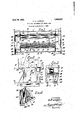
' 'lVith these and other objects in vview the invention consists in certain novel and use-y ful yfeatures of construction and combina tions'of parts as hereinafter described and claimed; and in order that itv may be fully understood reference is to be had to the accompanying drawing, in which- Figure 1 is a horizontal section of `a. portion of L Ford cartaken on the line of Figure 2, showing my improved tool box in operative' position; l
Figure 2 is a. vertical section taken on the line II-H of Figure 1, but with the tank indicated only by dotted linesand the trough partition omitted;
Figure taken 'substantially on the dotted line III, of Figure 1;l and y Figure 4 is a detail perspective view vof a part of onerofthe inner walls of either of the end receptacles of thelbox. l
In the said'drawing, 1 indicates the channel `side beams of the frame or chassis of a car, 2 the sides of the latter', 3 the wood for 3 is a fragmentary vertical section strip underlying the lside portions ofthe car at the bottom of' the'fbody thereof, 4 the front wall of the front seat, and`5 the back wall of said seat, thev said back wall in a plane below thefupp'e'r edge Aofwallj4, bow-' ing forwardlyl as atb.' 7 is the vcustomary hinged seat, which when in closed or normal position rests upon the offset frontportion 8 at the upper edge of wall 4, the ends of said seat being 'supported when closed, by the underlying flanges or arms Q'rigid with the sides 2,`as shown most clearly in Figure 3; The customary gas tank 10 is supported in the usual manner and is heldin place by the metallic. straps 11 secured tothe channel beams 1. The parts thusl farpreferred to,
are conventional Ford motor ear construction.
Arranged in thefu'pper 'corner of the chamber formed by the front and back walls of the seat, andicorresponding in length substantially to the tank 10,'is a troughorl re?,
cross piece 16 preferably of hard fiber, is
mounted upon the partition 14 and secured f at its ends under the flanges 13 ofthe trough. To provide compartments 17 and 18 between the sides of the ca-r'fand the endsof the gasov line tank 10, thel following construction isv` 'A provided: 19 `and 20' are plates which yconjointly correspond in contour to the space between the walls 4 and 5 fromthe `beams 3 to the seatftopf?, but in orderthat these plates may be readily secured in or removed `from position, it is necessary that they bear a movablerelation to each other as hereinvico afterveXplainedyThe plates are provided f at their lower edges withoutwardly projectingfeet or flanges 21 and 22 respectively, the front ends of thetlanges 21`over` lapping the'rear portions of the flanges 22,
lio
or flanges when the partitions constituting the inner side of the said compartments 1T and 18 are secured in position.
The plates 19 and 20 are arranged in overlapping position and are fastened tovget-lier by a. pin-andslot connection 24, so
that'tlie plates 20 may be slid rearwardly sufliciently to permitv the partitions as a whole to be fitted down into position,.after which the plates 20 can be slid forward and fit against the wall Il. They are then secured iirmly in position by means of the screws 23 before mentioned, and are further-- moresecured by means of angle brackets 25 tothe back wall 5y as shown. lBy this arrangement the compartments 17 and 18 are completely closed except at the top. The bottom however, is provided with a series of holes. 26 through which dust or dirt collectingl in the said compartments may be brushed lor flushed out by water. A tool box of the character described provides for storage of tools, chains and many accessories not necessary to mention, and utilizes v es with the structure of the car, a tool box space very desirable in small cars, it being contemplated `to provide a hasp 27 and lock 28 for fastening the seat top lirmly in place. lf preferred, the -twovplates may be sepa-k rately inserted and. then secured together as explained. After they kare secured in place the trough 12 is placed in position and bears at its endsr against the plates 20, and is secured reliably in such position by means of fastening devices 24. lVhen thus secured they trough 12 constitutes a rigid'brace against inward; rmovement ofthe said partitions at they front ends of the latter and is itself'supported by said partitions and by abutmentagainst the inner side of the front .wall t of the seat structure.
yTo avoid the necessity of holding the seat top 7 elevated when access to the gasoline tank or to Veither ofthe compartments Vof the tool box is desired, a brace is providedrconsisting of the rod 29 and shank 30 pivoted to the rod, and pivoted in turn at 31 to the back wall of tlietrough 12. By swinging this brace upwardly and then v'swinging rod 29 rearwardly, it can be utilized tosupport the seat top in open position as indicated by dotted lines in Figure 2,
Aand when said brace is not in use,.it is swung down to a horizontal clip 32 fastened to the trough in such position that the rod cannot rattle against the trough.
` From the above description it will be apparent that I have produced in conjunction having .ide lcompartments and a trough which will 'provide for the storage of nearly the tools that are ordinarily found useful in making temporary. repairs or adjust:
ments, and which furthermore is so secured in position that it constitutes in effect a solid portion of the cariand will not be` objectionable on the ground of rattling when the caris in motion.
I claim:
l. The combination inv a motor car of j pri-sing a pluralityvof members arranged in overlapping relation and secured together and to the car structure, each ymember hav- .ing a foot flange extending outward and engaging the adjacent side wall of the body of said, structure. l i j 2. VThe combination in ay motor car, of a tool box forming attachments comprising a` rpair of vertical partitions adjacent the sides of the car and between the front andbacky walls of akseat thereof, each partition com- 'j i prising a plurality of members arranged in overlapping `relation and secured together and to the car structure, and eachniember having a foot flange extending. outwardly and engaging theadjacent side wall of the j body of said structure, and a trough fitting against the innerside of the front` wall'vof. its ends tofthe said seat and secured at said partitions. l
3. The combination in a motorcar, of a tool box forming attachments comprising a pair of kvertical partitions-adjacent the sides of the car and `between the 'front and back walls of a seat thereof, each partition comprising a plurality of members arranged in overlapping relation and secured together i and to the car structure, and ,each member havinga foot flange extending outwardly and engaging the body of said structure, a` trough fitting against the inner partitions, and' a brace hinged to said trough and adapted .to hold the Ltopofy the seat of the car in open position.
adjacentside wall of the side of the front wallof-'f lsaid seat and secured at its ends tothe said 4. The combination in a motorv car of a tool box forming attachments a. pair of vertical sides of the car l comprising partitions adjacent the of the seat of-the car in openposition-or toextendi horizontally against the rear wall of said trough,and aispring clip carried by and `between the lfront i and back walls lof a seat thereof, eachv parthe body ofY said'struc'ture, a v
said trough for engagement with the free end of said brace to hold the same from rattling against said trough.
5. The combination n a motor car, of a tool box forming attachments comprising a pair of vertical partitions adjacent the sides of the car and between the yfront and back walls of a seat thereof, each partition comprising a plurality of members arranged in overlapping relation and secured together and to the car structure, and each member having a foot flange extending outwardly.
and engaging the adjacent side wall ofthe body ofthe ear, a troughitting against the inner side of the front wall ofl said seat and secured at its enc-ls to the said partitions7 a brace hinged to said` troughl and adapted to hold the top of the seat ofthe M oar in open position, and means for fastening the seat top inielosed position to `prevent access to the said trough and the comparte' ANDmsw w. LoVEJoY.
Priority Applications (1)
| Application Number | Priority Date | Filing Date | Title |
|---|---|---|---|
| US364010A US1459337A (en) | 1920-03-08 | 1920-03-08 | Tool-box attachment for motor cars |
Applications Claiming Priority (1)
| Application Number | Priority Date | Filing Date | Title |
|---|---|---|---|
| US364010A US1459337A (en) | 1920-03-08 | 1920-03-08 | Tool-box attachment for motor cars |
Publications (1)
| Publication Number | Publication Date |
|---|---|
| US1459337A true US1459337A (en) | 1923-06-19 |
Family
ID=23432651
Family Applications (1)
| Application Number | Title | Priority Date | Filing Date |
|---|---|---|---|
| US364010A Expired - Lifetime US1459337A (en) | 1920-03-08 | 1920-03-08 | Tool-box attachment for motor cars |
Country Status (1)
| Country | Link |
|---|---|
| US (1) | US1459337A (en) |
-
1920
- 1920-03-08 US US364010A patent/US1459337A/en not_active Expired - Lifetime
Similar Documents
| Publication | Publication Date | Title |
|---|---|---|
| US2978153A (en) | Cabinet structure for automotive vehicles | |
| US1453362A (en) | Tool-box attachment for motor vehicles | |
| US3558180A (en) | Bed attachment for tractor cabs | |
| US1914259A (en) | Gun support | |
| US1459337A (en) | Tool-box attachment for motor cars | |
| US1513227A (en) | Automobile | |
| US2080764A (en) | Vehicle bow support | |
| US1476051A (en) | Body for automobiles | |
| US1237750A (en) | Tool-case for automobiles. | |
| US1993675A (en) | Combined car bumper and light guard | |
| US775731A (en) | Combined trunk and desk. | |
| US1150954A (en) | Automobile-body. | |
| US1481543A (en) | Convertible vehicle body construction | |
| US1326877A (en) | Automobile-body | |
| US1652619A (en) | Tool box | |
| US2214937A (en) | Spare tire mounting | |
| US1896254A (en) | Detachable body | |
| US1974535A (en) | Motor vehicle | |
| US1323177A (en) | Atjtomobile-dqoe | |
| US1635976A (en) | Storage-battery container | |
| US1457190A (en) | Passenger vehicle | |
| US1837596A (en) | Vehicle body | |
| US1269929A (en) | Convertible automobile-body. | |
| US1373546A (en) | Engine-support clamp | |
| US1778788A (en) | Trunk-rack guard |