US1459313A - Operating urethroscope - Google Patents
Operating urethroscope Download PDFInfo
- Publication number
- US1459313A US1459313A US481030A US48103021A US1459313A US 1459313 A US1459313 A US 1459313A US 481030 A US481030 A US 481030A US 48103021 A US48103021 A US 48103021A US 1459313 A US1459313 A US 1459313A
- Authority
- US
- United States
- Prior art keywords
- tube
- instrument
- mirror
- operating
- section
- Prior art date
- Legal status (The legal status is an assumption and is not a legal conclusion. Google has not performed a legal analysis and makes no representation as to the accuracy of the status listed.)
- Expired - Lifetime
Links
Images

Classifications
-
- A—HUMAN NECESSITIES
- A61—MEDICAL OR VETERINARY SCIENCE; HYGIENE
- A61B—DIAGNOSIS; SURGERY; IDENTIFICATION
- A61B1/00—Instruments for performing medical examinations of the interior of cavities or tubes of the body by visual or photographical inspection, e.g. endoscopes; Illuminating arrangements therefor
- A61B1/307—Instruments for performing medical examinations of the interior of cavities or tubes of the body by visual or photographical inspection, e.g. endoscopes; Illuminating arrangements therefor for the urinary organs, e.g. urethroscopes, cystoscopes
-
- A—HUMAN NECESSITIES
- A61—MEDICAL OR VETERINARY SCIENCE; HYGIENE
- A61B—DIAGNOSIS; SURGERY; IDENTIFICATION
- A61B1/00—Instruments for performing medical examinations of the interior of cavities or tubes of the body by visual or photographical inspection, e.g. endoscopes; Illuminating arrangements therefor
- A61B1/06—Instruments for performing medical examinations of the interior of cavities or tubes of the body by visual or photographical inspection, e.g. endoscopes; Illuminating arrangements therefor with illuminating arrangements
- A61B1/0661—Endoscope light sources
- A61B1/0676—Endoscope light sources at distal tip of an endoscope
Description
June 19, 1923.
S. REISLER ET AL OPERATING URETHROSCOPE 1921 2 sheets-sheet Filed Juhe' 2a nritll M/zzesses:
June 19, 1923.
S. REISLER ET AL OPERATING URE'THROSCOPE Filed June 28, 1921 2 Sheets-Sheet 2 5 n a e 2 C 4 1 Inventor Wt/zesses @W gww mam 6% Patented June 19, 1923.
'' uniren s'rares PATENT OFFICE.-
PHILADELPHIA,
PENNSYLVANIA.
OPERATING 'URETHROSCOPE.
Application filed June 28, 1921. Serial No. 481,030.
1 0 all to 1mm it may concern Be it known that we, Dr. SIMON REIsLER and HEnRMAN-N B. ToBIAs, citizens of the United States of America, and residents,.respectively, of the city of Indianapolis, in the county of Marion and State of Indiana, and of the city of Philadelphia, in the county of Philadelphia and State of Pennsylvania, have invented a new and Improved Operating Urethroscope, and do hereby declare the following "to be a full clear, and exact description of the same. reference being had to the accompanying drawings, forming a part of the specifications, and to the reference numbers marked thereon.
0111' present invention relates to an instrument intended for the surgical treatment of the anterior urethra.
The main object of the invention is to provide an instrument to facilitate the surgical technique introduced by Dr. Simon Reisler for the cure of chronic anterior urethritis.
A further object of the invention is to provide an instrument that can be easily operated and also used as an endoscope aero-. scope or with attachments as a cystosc ope.
The attachments mentioned above will form the basis of future applications.
For the purpose of illustration the instrument is shown toa very exaggerated scale while in actual practice the circumference of the cross section is only 26 millimeters.
In carrying out our invention, we provide a main tube having a top window along most of its length and a telescoping tube having a shorter window, both tubes being open at the rear end; the telescoping tube having at the front end devices for propelling through the tubes illuminating, res fleeting. focusing, operating. irrigating and aspirating tools, all as will be hereinafter more fully described, the main features being pointed out in the appended claims. 1
Figure 1 shows an isometric perspective view of the instrument with mainelements line 22 of Figure .6.
Figure 3 shows a vertical section through the front end of the instrument taken on line 3-3 of Figures 4 and 5.
Figure 4 shows a view ofthe front end of the instrument and its relation to the telescoping tube taken on line t4 of Figure 3, having the reflecting mirror and its carrier removed.
Figure 5 is a section through the instrument taken on line 55 of Figure 3.
Figure 6 shows a cross section through the rear end of the instrument taken on line 66' of Figure 2.
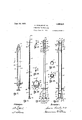
Figure 7 is a vertical section along the long axis ofthe main tube with the obturator in position to facilitate'its introduction in the urethra.
Figure '8 is a vertical section along the long axis of'the Folliculotome taken on lines 8 of Figures 9 and 10.
Figure 9 is a cross-section to the operating end of the Folliculotome taken on line 9 of Figure. 8 and showing the operating knife. i
Figure 10 a cross section through th body of the Folliculotome taken .on line 10 of Figure-8.
' Figure 11 is a top view of the instrument elongated to approximate the relative pros portion between parts,
Figure 12- is a vertical section along the long axis of the instrument as shown by Figure 11, having the front reflecting mirror and carrier removed. c
Figure 13 is a cross section through the main tube and obturator taken on line 13 of Figure 7.
Figure 14 is a cross section. thru the telescopihg tubes in their circular form instead of the ovoid. form shown elsewhere for the present illustration.
F igure- 15 is a cross section thru the secondar'y' tube taken on line 15--15 of Fig.
3, showing the anchoring chair with the light carrier removed.
i The instrument constructed in accordance with our invention embodies amain tube 15, formed of very thin section and for the present illustration of an ovoid form.
The front end of the tube 15 is made in tegral with ashiel 1.6 through the flange 1.7.
The rear end is cut away as shown at 18 to permit endoscopic operations.
The top of the main tube is provided with an opening or window 19 throughout most of its length to permit folliculotomie operations at any point of the urethra.
A secondary tube 20 is PIOVlClBCl to snugly fit and telescopeinto the main tube 15. The rear end of the secondary tube is cut away as shown at 21 to permit endoscopic operations. The top part of opening 21 is extended longitudinally as shown at 22 to form a parabolic cut for the purpose hereinatter. described.
" by springlock pins 26.
and s0 are provided to secure t'h An anchoringchair 27 is provided integral with the lower front end of secondary tube 20, having an opening 28 thru which the light carrier is passed.
T he top flange of this chair is curved and is provided with side wings '29 so arranged as not to interfere with the optical system oflthe instrument providing a top rest for the minor in'strun'ients or anchoring orifices 30 on either side of light carrier opening 28. front end of the funnel is provided with a' reino-vablecover 31 secured in place by pin 32, tongue 33 and pivoted side clips 34, the jointbeing sealed by a suitable gas ket.
The top of the cover 31 is extended at 35 and provided with side stops intended to receive and support a. reflecting mirror frame, hereinafter described.
Integral with the front cover 31, is a tube 37 open at both ends and flanged at 38 to hold a lens. Snugly fitting inner sleeves v p e lenses 4 1 and 42 at a proper spacing. f
An opening 43 is provided in the front cover to admit the light carrierminto the tubes.
Below opening 43 and on either side thereof large openings 44 and 45 are provided covered by removable plugs {i6 and 47.
These plugs have eccentric holes 481m admitting); tool. into the tubes and may be used separately or be a slidable part of the various tools used.
Some of these plugs have no holes intended to render instrument tight against air or liquids, while other plugs are provided with valved outlets to facilitate the introduction into the instrument or extraction therefrom are pivoted to the flanges 51 and 52 of the mirror frame by rivets 58. Depressions 59 are provided in the flanges56 and 57 of the mirror plate flanges intended to press against flanges'51 and 52 of the mirror frame and thereby hold said mirror at any desired angle.
The mirror carrier can also be made in- I tegral with the sleeve 40 omitting in such case the lip 50 and thereby permitting the radial adjustment of the mirror. I
A light carrier 60 is provided having a standard electric connection plug 61 at the front end and a reduced section 62 at the rear end. e
As is usual. in these light carriers the center rod 63 carries one electric current form while the outer shell 64k carries the other electric current torin being separated by the insulating; tube 65. s
.The circuit is closed by. the lamp 66 screwed through a plug 67 into the rear end of light'carrier. i
The base 68 of the lamp .isas large as the main tube of light carrier forming thereby a stop tor the reduced section 62 of the light carriertube. Z
A rear reflecting mirror 69 provided mounted on a mirror plate 70 and held in place by tongues 71.
l lan'e'es 72 are provided integral with mirror plate thru which supporting pivot pin TS'is passed and secured to the mirror carrier frame 74, 1
The mirror carrier istorined to fit snugly The obtui'ator shown inFigure '7 is made to fit snugly in the main tube l5,'having a pointed end '79 to facilitate introduction into the urethra, a reduced section 80 of sufficient width to cover the top window,19 and a handle 81. I The operating tool with which this'improved urethroscope is vitally linked is as named for the present purpose the Folliculotome.
The Folliculotome. of a very small cross section is shown in Figures 1 and 8 as formed of a tube 82, the front end of which is provided with a finger loop handle 88 or other suitable gripping device- The rear or operating end of the Folliculoton'ie is cut away for a suitable dis While we have shown the instrument hav-- iug an ovoid cross section of tubes'it can also be made of a round cross section as shown in Figure 14, all other parts'and functions remaining the same. 1
The operation of this instrument with the above description in view will be readily understood. The medical operating technique requiring this instrument is the splitting of the follicle or lacunae without injuring the adjacent uretheal mucosa, in cases of chronic anterior urethritis, removing thereby the inflammatory process in the mucuous glands, the glands of littre and the lacunae of Morgagni. This operation is performed by the knife 8 beiug moved toward the end 83 after said end libeen introduced into the follicle. The action of theknife is: secured by the pressure of knob 86 againstthe spring- 87 and grip ring 88 and transmitting sai'dlongitudinal motion, to the knife through rod This knife is operated through windows 19 and of the urethroscope orth-rough the end windows 18 and 21. 0
Preliminary to this operation the instrument is introduced into the urethra by the aid if the obturator in Figure 7 which is afterwards removed leaving the main tube in position.
The secondary tube 20 is then introduced into the main tube 15, with the reflecting parts in position, including light carrier 60. rear mirror 69, front mirror 53 and. focusing lenses 4L1 and 42.
The rear mirror 69 can be moved longitudinally by sliding light carrier back and forth the required distance to place both light and mirror in required position,
The rear mirror 69 can. be tilted to, any
desired angle icy-introducing a Wire hookthrough frontopening 4st and engaging holes 76 ofmi-rror plate, moving back and forth asrequired. v
The'rear mirror may thus be laid flat as shown by dotted lines at 100 and thereby offer a clear endoscopic view 'allowing at the same time the sliding of the lamp 566 nearer the end of the tube and under the mirror plate.- The rear refle'ctingmirror is'prefer ably of a slightly convex form to secure a small reduction" of the membranes under observation.
The lenses 41 and 4-2 are of suchfocal caliber as to receive and correct the-"reflection presented by the rear mirror. 5 The front reflecting mirror is preferably of a slightly concave form tosecure a small enlargement o1 the projection from the lenses 42 and 4:1.
When a direct'view is desired through they instrument the front'reflecting mirror may be lowered against the light carrier rod or.
it can be removed entirely with its supporting frame.
'VVhen desired, the front cover or funnel can be entirely removed and-the operating tools can then be handled through the open front end. 7
The Folliculotome is introduced-into the tubes through the opening 47 and hole 4-8 of plug it is then pa'ssedlu'nder the flange 29 of chair 27 and thereby secures two supporting points to'steadyit. In certain instances the omission of thisnchair would be desirable. I 1 Its angular position re-lative to the axis of the tubes or the field of operation can be varied bythe radial rotation of plug '45.-
Through the plug 44:: additional instru-. ments or tools can be introduced such as,
aeroscopic dilating tube, canulas 'for irri- I gating or aspirating, filliforms or probes, galvanic needles applicators or flu-id and? solid medicinal agents. i i I .For cystoscopic examinations "orgtre'atr ment the inner. tube 20 is elongated-by an attachment (the basisof a future. application) and is pushedbackits-full. length'and passed through the end 18 of main tube 1 5.
By reversing the inner tube or by turning the entire instrument around andadjusting.
its mirror lateral observations orthe examination and treatmentof vital parts such asurethral openings" through the capaciou's vices, a'folliculotome and-other means for aeroscop'ic aIIClGDCl OSCQPIC purposes thereby COIUHEgWItlHI'L the scope ofour principleand invention I Having thus described our invention, What We claim anddesire to'secure by Letters Pat- 'ent, is: 1. In an instrument of the character described, the combination WithtWo telescopingzurethroscopic tubes having-rear end WllF doWs; an operating front; and an adjustable illuminated optical system for reflecting the field of operation to the operator at right angles to the axis of tlieinstruments, of a long lateral WVlIlCiOW in both tubes and a Folliculotome operating through'said I lateral WlTlClO-WS. i
'2; In an instrument ofthe character cescribed, the combination of two telescoping tubes open :at the front :and rear ends and both PI'OVldEiClWlth long lateral Windows; a
' Folliculotomeoperating through said lat eral Windows; 'airilluminated optical sys tem for reflecting the field of operation r0 'tlie -operator at right angles to the axisof the instrument and means for adjusting theilluminated optical system and for sealing the instrument tofacilitate aeroscopic and endoscopic operations. i 3. In an instrument of the character described, the combination of a main tubeand a secondary telescoping tube, both provided With end and long lateral Windows; niech an-ism at the front of the'secondary tube for admitting instruments thereto an adjustable illuminated optical system for the in direct reflection and observation of the field of operation; and a Folliculotome, operat ingythrough said lateral WlIlClOWS and com: prising a tube With a guiding groove at one end; a sliding knife Within said guiding groove and aspring cont-rolled operating mechanism at the opposite end extending through said tube to slide said knife relative to the end of said guiding groove.
4. In an instrunient'of the character de "ments therein and for sealing said tube for aeroscopicoperatioii; and an optical system Within the inner tube comprising a slidable light carrier; a slidable rear reflecting mirror controlled by said light carrier; mechanism for supporting and varying the angle of said rear mirror; a plurality of lenses at the front end of the inner tube for receiving and correcting the image from rear mirror.
and a front reflecting mirror mounted on a removable frame, having mechanism for' varying the angle of said mirror relative to the axis of the optical system to facilitate indirect observation of'the field of operation;
scribed, the combination of a main tube and a secondary tube, both providedwith end and long lateral windows; a Folliculotomel operating through said lateral Windows; an adjustable illuminated optical system forthe indirectreflection and observation of'the field of operation; a protecting shield at the front end of main tube, and operating mechanism at the front end. of thesecondary tube comprising a removable funnel; With means forfsecuring it to secondary tube; a removable front coverlwith means for securing it to the large'end ofsaid funnel; means upon said front cover for supporting i and securing the plurality of lenses of the optical system and the front reflecting mirror; perforations in said cover for admitting to the inner tube the light carrierand operatin instruments and *plugsffor covering said perforation, having eccentric bores for supporting operating instrument andfor' controlling theirangle relative to long axis of inner tube by their rotation in said perforaoptical mechanism at the front-end of tele-' scoping. tube for absorbing,
I correcting and indirectly pro ecting the image from rear reflector; mechanism at front end of telescoping tubefor admitting instruments'there to and sealing said tube for aeroscopic operation; and long lateral Windows provided in both tubes having their ends of parabolic form to prevent injury to the membrane of urethra duringtheir telescoping action; and a Folliculotome extending through said long lateral Windows for splitting the inflamed follicle or lacunae in the urethra.
In testimony whereof We have signed our names to this specification in the presence of two subscribing witnesses.
, SIMON REISLER, M. D. Witnesses:
JOHN K. Bunenss, P. F. THRUSH. v V HER-MANN 'B. TOBIAS. vWitnesses: I i
EDW. N. VoLnnR,
B. M. AUCHTER;
5; In an instrument ofthe character de-
Priority Applications (1)
| Application Number | Priority Date | Filing Date | Title |
|---|---|---|---|
| US481030A US1459313A (en) | 1921-06-28 | 1921-06-28 | Operating urethroscope |
Applications Claiming Priority (1)
| Application Number | Priority Date | Filing Date | Title |
|---|---|---|---|
| US481030A US1459313A (en) | 1921-06-28 | 1921-06-28 | Operating urethroscope |
Publications (1)
| Publication Number | Publication Date |
|---|---|
| US1459313A true US1459313A (en) | 1923-06-19 |
Family
ID=23910300
Family Applications (1)
| Application Number | Title | Priority Date | Filing Date |
|---|---|---|---|
| US481030A Expired - Lifetime US1459313A (en) | 1921-06-28 | 1921-06-28 | Operating urethroscope |
Country Status (1)
| Country | Link |
|---|---|
| US (1) | US1459313A (en) |
Cited By (5)
| Publication number | Priority date | Publication date | Assignee | Title |
|---|---|---|---|---|
| US2532043A (en) * | 1946-06-18 | 1950-11-28 | American Cystoscope Makers Inc | Instrument for retrograde electrosurgical resection |
| US2705490A (en) * | 1949-08-05 | 1955-04-05 | Zeiss Carl | Microscope for the examination of living tissues in body cavities |
| US4706656A (en) * | 1985-05-15 | 1987-11-17 | Olympus Optical Co., Ltd. | Endoscope device with tool channel |
| US5782750A (en) * | 1997-03-06 | 1998-07-21 | Gluskin; Lawrence E. | Endoscopy control end and biopsy channel shield |
| WO2009094548A1 (en) * | 2008-01-25 | 2009-07-30 | Tyco Healthcare Group Lp | Endoluminal access device |
-
1921
- 1921-06-28 US US481030A patent/US1459313A/en not_active Expired - Lifetime
Cited By (8)
| Publication number | Priority date | Publication date | Assignee | Title |
|---|---|---|---|---|
| US2532043A (en) * | 1946-06-18 | 1950-11-28 | American Cystoscope Makers Inc | Instrument for retrograde electrosurgical resection |
| US2705490A (en) * | 1949-08-05 | 1955-04-05 | Zeiss Carl | Microscope for the examination of living tissues in body cavities |
| US4706656A (en) * | 1985-05-15 | 1987-11-17 | Olympus Optical Co., Ltd. | Endoscope device with tool channel |
| US5782750A (en) * | 1997-03-06 | 1998-07-21 | Gluskin; Lawrence E. | Endoscopy control end and biopsy channel shield |
| WO2009094548A1 (en) * | 2008-01-25 | 2009-07-30 | Tyco Healthcare Group Lp | Endoluminal access device |
| US20090192466A1 (en) * | 2008-01-25 | 2009-07-30 | Tyco Healthcare Group Lp | Endoluminal access device |
| US8162895B2 (en) | 2008-01-25 | 2012-04-24 | Tyco Healthcare Group Lp | Endoluminal access device |
| US8652105B2 (en) | 2008-01-25 | 2014-02-18 | Covidien Lp | Endoluminal access device |
Similar Documents
| Publication | Publication Date | Title |
|---|---|---|
| US2482971A (en) | Self-illuminated transparent proctoscope | |
| US2296793A (en) | Surgical retractor | |
| US4572180A (en) | Lighted ear canal curette instrument | |
| US3195536A (en) | Illuminated appliances | |
| US1459313A (en) | Operating urethroscope | |
| US1891054A (en) | Surgical instrument | |
| US2070820A (en) | Laryngoscope | |
| US1303135A (en) | Reinhold h | |
| US2182390A (en) | Surgical device | |
| US2236842A (en) | Endoscopic instrument | |
| US432614A (en) | Surgical apparatus | |
| US2023945A (en) | Endoscope | |
| US1551770A (en) | Surgical instrument | |
| US1150214A (en) | Cystoscope. | |
| US2297799A (en) | Viewing device | |
| US1849701A (en) | Speculum | |
| JP2016067818A (en) | Slit-lamp microscope | |
| US672317A (en) | Speculum. | |
| US1764455A (en) | Air-emitting and electric-light-actuating mirror | |
| US1345406A (en) | Mabk cubbon bimmeb | |
| US339754A (en) | foote | |
| US2088735A (en) | Forehead lamp for doctors | |
| US20190200853A1 (en) | Rectoscope | |
| US2012597A (en) | Nasal and aural speculum | |
| US1387770A (en) | Dental mirror |