US1451663A - Speed regulator for phonographs - Google Patents
Speed regulator for phonographs Download PDFInfo
- Publication number
- US1451663A US1451663A US518767A US51876721A US1451663A US 1451663 A US1451663 A US 1451663A US 518767 A US518767 A US 518767A US 51876721 A US51876721 A US 51876721A US 1451663 A US1451663 A US 1451663A
- Authority
- US
- United States
- Prior art keywords
- friction
- motor
- disc
- speed
- speed regulator
- Prior art date
- Legal status (The legal status is an assumption and is not a legal conclusion. Google has not performed a legal analysis and makes no representation as to the accuracy of the status listed.)
- Expired - Lifetime
Links
- 239000000314 lubricant Substances 0.000 description 2
- 238000010276 construction Methods 0.000 description 1
- 239000002783 friction material Substances 0.000 description 1
- 239000010985 leather Substances 0.000 description 1
- 239000000463 material Substances 0.000 description 1
- 238000000034 method Methods 0.000 description 1
- 230000001105 regulatory effect Effects 0.000 description 1
- 230000000153 supplemental effect Effects 0.000 description 1
Images
Classifications
-
- G—PHYSICS
- G05—CONTROLLING; REGULATING
- G05D—SYSTEMS FOR CONTROLLING OR REGULATING NON-ELECTRIC VARIABLES
- G05D13/00—Control of linear speed; Control of angular speed; Control of acceleration or deceleration, e.g. of a prime mover
Definitions
- the object of my invention is to adapt a phonograph motor to produce a certain turn table speed without requiring labor, thought or uncertain adjustments.
- a further object of my invention is to adapt to phonograph motor previously set for a certain speed to be changed to another certain speed upon the mere manipulation of a control without the necessity of exercising thought or labor. and eliminating un certainty of adjustment.
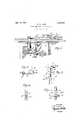
- Fig. l is a perspective view of a part of a phonograph motor showing my speed regulator in operative position thereon;
- Fig. 2 is aview of the regulator arm in operative position to a determined speed of the motor
- Fig. 3 is a detail view partly in cross section of the supporting and adjusting means for the friction pad
- Fig. 4 is a side view of the bracket shown in Figs. 1 and 3;
- Fig. 5 is a plan view of the control.
- 2- is a motor frame of usual construction in which is shown mounted a. conventional governor and governor disc (3 and means for operating the same.
- bracket 1 Mounted on the motor frame 2 and adapted to lateral adjustment with reference thereto is a bracket 1.
- This bracket is secured to said motor frame by means of the screw 7 which extends through the elongated. slot 14: of the bracket and into the motor frame 2.
- This bracket 1 is provided with spring arm 3 shown as being screwedthereto but which may be secured thereto in any other convenient manner.
- the bracket 1 is also provided with a rigid arm 15 which acts as a base for the adjusting screw 12% in its action on the spring arm 3. The free used for friction purposes.
- friction nia-- end of the spring arm 3 is provided with friction medium retaining means.
- Such medium may be leather or other material In said fric into the friction pad 5.
- the end of this screw entering the pad is positioned back of the face of the friction pad 5 before the same has become compressed by the action of the disc 6 thereon.
- the disc is therefore given a resilient resistance in its travel against the friction pad until its travel is checked by the influence of the screw 11 which limits the travel of the disc in that direction and consequently limits the speed of the motor.
- the shaft 8 extends through the motor frame 2 and is supported thereby. At the lower end of said shaft is mounted in adjustable position thereto an arm 10 adapted to control the pressure of the friction material 5 on the governor disc 6.
- This arm 10 is attached to said shaft 8 by the screw 16 which passes through an elongated slot 17 in said arm and into the lower end of the shaft 8, thus adapting the arm 10 to lateral movement with reference to said shaft 8. 1
- a lever 18 which is rigidly attached to the shaft 8 so as to control the arcuate movement of the same. 011 the motor board 19 is attached a plate 20 having grooves therein 21 and 21 over which the lever 18 is adapted to slide and be positioned in either of said grooves.
- the speed of the motor is adj usted in the usual way to a maximum speed.
- This for practicable purposes is preferably set at the speedof turn table revolutions per minute and for this reason I have designated the numeral 80 on the plate 20.
- .lrhonograph records are made by different companies for reproduction at different speeds, some providing that the reproduction shall be at the rate of 78 revolutions per minute while others time the records so as to be played at 80 revolutions per minute. For this reason my speed regulator is adjusted so as to control the turn table speed at either 78 or 80 revolutions per minute by a simple manual manipulation.
- the adjustment of the pad with relation to the governor disc 6 is effectd by manipulation of the adjusting screw 13 thereon which acts directly upon the spring arm 3, and supplemental adjusting means ll which acts directly on the governor ,disc 6.
- the pressure of the cam 22 is regulated by the adjustment of the arm lOnndei' the screw 16.
- any desirable lubricant may be inserted in the cup 12 or the pad itselfmay be. impregnated with lubricant, or both methods may be used.
- a speed regulator for phonographs in combination with a phonograph motor embodying a friction disc, a. friction device adapted to act on said disc, said friction device con' prising a bracket member, bifurcated arms extendin therefrom, one of said supporting arms being rigid and the other of said arms being resilient, and adjusting means carried by said rigid member adapted to control the adjustment of the resilient member.
- a friction device adapted to act on said disc, said friction device comprising a bracket member, bifurcated arms extending therefrom, one of said arms being rigid and'the other of said arms being resilient, adjusting means carried by said rigid member to control the adjustment of the resilient member, and adjusting means carried by said resilient member adapted to control the adjustment thereof with reference to the friction disc.
- a speed regulator for phonograpl'is in combination with. a. phonograph motor embodying a friction disc, a friction device adapted to act on said disc, a spring arm supporting said friction device, means for said spring arm in the frame of the motor, said friction device being adjustable with reference to its action on said friction disc, a cam adapted to press said friction device against said friction disc, and means for giving the said cam arcuate movement for said purpose.
- a speed regulator for phonogra'phs in combination with a phonograph motor embodying a friction disc; a friction device adapted to act on said friction disc a spring arm supporting said friction device, supporting means for said spring arm in the frame of the motor, a cam adapted to act upon said spring arm and press the friction device against the friction disc, a shaft, means for rigidly attaching one end of said cam to said shaft, and a lever rigidly attached to said shaft at its other end, the manipulation of which is adaptedto change the turn table speed of the motor.
Landscapes
- Physics & Mathematics (AREA)
- General Physics & Mathematics (AREA)
- Engineering & Computer Science (AREA)
- Automation & Control Theory (AREA)
- Holding Or Fastening Of Disk On Rotational Shaft (AREA)
Description
E. W. LADD Apr. 10, 1923 1,451,663
SPEED REGULATOR FOR PHONOGRAPHS Filed Nov. 50, 1921 INVENTOR ATTORNEY Patented Apr. 10, 1923,
EARNEST V. IiADD, OF NEW YORK, N. Y., ASSIG-NOR OF ONE- HALF TO CHARLES F. HERRMANII, OF NEX -T YORK, N. Y.
SPEED REGULATOR FOR PHONOGBAPHS.
Application filed November 30, 1921. Serial No. 518,767.
To all whom it may concern:
Be it known that I, Ennnnsr lV. Lam), a citiz n of the United States, residing in the borough of Manhattan, city, coimty, and State of New York, have invented certain new and useful improvements in Speed Regulators for Phonographs. of which the following is a specification, reference be 'ing had to the accompanyii'ig drawings,
which form a part of the same.
The object of my invention is to adapt a phonograph motor to produce a certain turn table speed without requiring labor, thought or uncertain adjustments.
A further object of my invention is to adapt to phonograph motor previously set for a certain speed to be changed to another certain speed upon the mere manipulation of a control without the necessity of exercising thought or labor. and eliminating un certainty of adjustment.
Other objects will be apparent from read ing this specification in connection with the accompanying drawings in Wl11Pl1- I Fig. l is a perspective view of a part of a phonograph motor showing my speed regulator in operative position thereon;
Fig. 2 is aview of the regulator arm in operative position to a determined speed of the motor;
Fig. 3 is a detail view partly in cross section of the supporting and adjusting means for the friction pad;
Fig. 4 is a side view of the bracket shown in Figs. 1 and 3; and
Fig. 5 is a plan view of the control.
Referring now in detail to the drawings in which similar reference characters refer to similar parts, 2- is a motor frame of usual construction in which is shown mounted a. conventional governor and governor disc (3 and means for operating the same.
Mounted on the motor frame 2 and adapted to lateral adjustment with reference thereto is a bracket 1. This bracket is secured to said motor frame by means of the screw 7 which extends through the elongated. slot 14: of the bracket and into the motor frame 2. This bracket 1 is provided with spring arm 3 shown as being screwedthereto but which may be secured thereto in any other convenient manner. The bracket 1 is also provided with a rigid arm 15 which acts as a base for the adjusting screw 12% in its action on the spring arm 3. The free used for friction purposes.
tion retaining means is shown friction nia-- end of the spring arm 3 is provided with friction medium retaining means. Such medium may be leather or other material In said fric into the friction pad 5. The end of this screw entering the pad is positioned back of the face of the friction pad 5 before the same has become compressed by the action of the disc 6 thereon. The disc is therefore given a resilient resistance in its travel against the friction pad until its travel is checked by the influence of the screw 11 which limits the travel of the disc in that direction and consequently limits the speed of the motor.
The shaft 8 extends through the motor frame 2 and is supported thereby. At the lower end of said shaft is mounted in adjustable position thereto an arm 10 adapted to control the pressure of the friction material 5 on the governor disc 6. This arm 10 is attached to said shaft 8 by the screw 16 which passes through an elongated slot 17 in said arm and into the lower end of the shaft 8, thus adapting the arm 10 to lateral movement with reference to said shaft 8. 1
At the opposite end of the shaft 8 is provided a lever 18 which is rigidly attached to the shaft 8 so as to control the arcuate movement of the same. 011 the motor board 19 is attached a plate 20 having grooves therein 21 and 21 over which the lever 18 is adapted to slide and be positioned in either of said grooves.
in. operation the speed of the motor is adj usted in the usual way to a maximum speed. This for practicable purposes is preferably set at the speedof turn table revolutions per minute and for this reason I have designated the numeral 80 on the plate 20. .lrhonograph records are made by different companies for reproduction at different speeds, some providing that the reproduction shall be at the rate of 78 revolutions per minute while others time the records so as to be played at 80 revolutions per minute. For this reason my speed regulator is adjusted so as to control the turn table speed at either 78 or 80 revolutions per minute by a simple manual manipulation. The
Ill)
motor therefore having been previously adjusted so that its speed will turn the turn table at 80 revolutions per minute, this will be the speed at which the record will be carried so long as no control is exercised thereon by my speed regulator. When it is desired to change the speed of the motor from 80 to 78, the handle 9 operating the lever 18 is shifted so as to carry thesaid lever from the 80 position to the 78 position. This shifting gives an arcuate movement to the shaft- 8 and to the attached arm 10 which is. provided with a cam extension which bears upon the free end of the spring arm 1% in which is contained the friction pad and przses the same against the governor disc (3 thus reducing the speedof the motor to 78. The adjustment of the pad with relation to the governor disc 6 is effectd by manipulation of the adjusting screw 13 thereon which acts directly upon the spring arm 3, and supplemental adjusting means ll which acts directly on the governor ,disc 6. The pressure of the cam 22 is regulated by the adjustment of the arm lOnndei' the screw 16.
To lubricate the friction pad any desirable lubricant may be inserted in the cup 12 or the pad itselfmay be. impregnated with lubricant, or both methods may be used.-
I have shown and described what I believe to bathe best-embodiment of my invention as the same is attached to a conventional phonograph motor. I do not wish to be limited, however, to the embodiment shown and described, but what I desire to cover by Letters Patent is set forth in the annexed claims.
Claims:
1. In a speed regulator for phonographs, in combination with a phonograph motor embodying a friction disc, a. friction device adapted to act on said disc, said friction device con' prising a bracket member, bifurcated arms extendin therefrom, one of said supporting arms being rigid and the other of said arms being resilient, and adjusting means carried by said rigid member adapted to control the adjustment of the resilient member.
2. In a speed regulator for phonographs, in combination with a phonograph motor embodying a friction disc, a friction device adapted to act on said disc, said friction device comprising a bracket member, bifurcated arms extending therefrom, one of said arms being rigid and'the other of said arms being resilient, adjusting means carried by said rigid member to control the adjustment of the resilient member, and adjusting means carried by said resilient member adapted to control the adjustment thereof with reference to the friction disc.
3. In a speed regulator for phonograpl'is, in combination with. a. phonograph motor embodying a friction disc, a friction device adapted to act on said disc, a spring arm supporting said friction device, means for said spring arm in the frame of the motor, said friction device being adjustable with reference to its action on said friction disc, a cam adapted to press said friction device against said friction disc, and means for giving the said cam arcuate movement for said purpose.
l. In a speed regulator for phonogra'phs, in combination with a phonograph motor embodying a friction disc; a friction device adapted to act on said friction disc a spring arm supporting said friction device, supporting means for said spring arm in the frame of the motor, a cam adapted to act upon said spring arm and press the friction device against the friction disc, a shaft, means for rigidly attaching one end of said cam to said shaft, and a lever rigidly attached to said shaft at its other end, the manipulation of which is adaptedto change the turn table speed of the motor.
EARNESTIV. LADD.
Priority Applications (1)
| Application Number | Priority Date | Filing Date | Title |
|---|---|---|---|
| US518767A US1451663A (en) | 1921-11-30 | 1921-11-30 | Speed regulator for phonographs |
Applications Claiming Priority (1)
| Application Number | Priority Date | Filing Date | Title |
|---|---|---|---|
| US518767A US1451663A (en) | 1921-11-30 | 1921-11-30 | Speed regulator for phonographs |
Publications (1)
| Publication Number | Publication Date |
|---|---|
| US1451663A true US1451663A (en) | 1923-04-10 |
Family
ID=24065410
Family Applications (1)
| Application Number | Title | Priority Date | Filing Date |
|---|---|---|---|
| US518767A Expired - Lifetime US1451663A (en) | 1921-11-30 | 1921-11-30 | Speed regulator for phonographs |
Country Status (1)
| Country | Link |
|---|---|
| US (1) | US1451663A (en) |
-
1921
- 1921-11-30 US US518767A patent/US1451663A/en not_active Expired - Lifetime
Similar Documents
| Publication | Publication Date | Title |
|---|---|---|
| US2645495A (en) | Recording and translating device | |
| US1451663A (en) | Speed regulator for phonographs | |
| US2948783A (en) | Cutter control means for cutting recording grooves | |
| US1949826A (en) | Sewing machine motor-controller | |
| US2273938A (en) | Turntable speed governor | |
| US1893126A (en) | Regulator device | |
| US1539460A (en) | Phonograph stop | |
| US1325673A (en) | Speed-kegttlatok | |
| GB647854A (en) | Improvements in and relating to the control of pick-ups in talking machines with magnetic sound recording on disc-shaped sound carriers | |
| US2154029A (en) | Marking device for index blanks | |
| US755851A (en) | Combined regulator and brake for talking-machines. | |
| US1432943A (en) | Speed governor for phonographs and other purposes | |
| US1284184A (en) | Speed-regulator and brake for talking-machines. | |
| US3125344A (en) | Control mechanism for record-cutting heads | |
| US2937876A (en) | Record player comprising a device for setting different turntable speeds | |
| US1304233A (en) | Best available copy | |
| US1625093A (en) | Speed-control mechanism | |
| US1547374A (en) | Sound-reproducing machine | |
| US1580549A (en) | Motor governor | |
| US1419914A (en) | Stop device for phonographs | |
| US2286187A (en) | Speed control mechanism | |
| US897053A (en) | Mechanism for driving the diaphragms of disk phonographs. | |
| US738125A (en) | Speed-regulator. | |
| US1131782A (en) | Phonograph-recorder. | |
| US1455326A (en) | Automatic stop for phonographs |