US1450737A - Typewriting machine - Google Patents
Typewriting machine Download PDFInfo
- Publication number
- US1450737A US1450737A US462890A US46289021A US1450737A US 1450737 A US1450737 A US 1450737A US 462890 A US462890 A US 462890A US 46289021 A US46289021 A US 46289021A US 1450737 A US1450737 A US 1450737A
- Authority
- US
- United States
- Prior art keywords
- fingers
- stencil
- frame
- platen
- holder
- Prior art date
- Legal status (The legal status is an assumption and is not a legal conclusion. Google has not performed a legal analysis and makes no representation as to the accuracy of the status listed.)
- Expired - Lifetime
Links
- 229940000425 combination drug Drugs 0.000 description 2
Images
Classifications
-
- B—PERFORMING OPERATIONS; TRANSPORTING
- B41—PRINTING; LINING MACHINES; TYPEWRITERS; STAMPS
- B41J—TYPEWRITERS; SELECTIVE PRINTING MECHANISMS, i.e. MECHANISMS PRINTING OTHERWISE THAN FROM A FORME; CORRECTION OF TYPOGRAPHICAL ERRORS
- B41J13/00—Devices or arrangements of selective printing mechanisms, e.g. ink-jet printers or thermal printers, specially adapted for supporting or handling copy material in short lengths, e.g. sheets
- B41J13/10—Sheet holders, retainers, movable guides, or stationary guides
- B41J13/12—Sheet holders, retainers, movable guides, or stationary guides specially adapted for small cards, envelopes, or the like, e.g. credit cards, cut visiting cards
Definitions
- a carriage 10 is mounted in the usual manner upon front and rear rails (not shown), and comprises a frame having end walls 11 and 12 connected at their lower ends by a tie-rod 13 and at their upper ends by a tie-strap 14 and a tie-rod 21.
- a short platen 15 is mounted upon an axle or shaft 16, journaled in the end walls 11 and 12,
- the combination with a revolub e platen, of a stencilholder for maintaining the stencil in fixed relation to itself comprising a pair of fingers, and means on said fingers for supporting a stencil-frame at its bottom edge, each of said fingers having a portion of its surface formed into a rearward projection near the upper edge of said stencil-frame for forcing the upper edge of said stencilframe rearwardly to curve said stencilframe around the platen.
Landscapes
- Manufacture Or Reproduction Of Printing Formes (AREA)
Description
Apr. 3, 1923. 1,450,737
J. A. B. SMITH TYPEWRITING MACHINE Filed Apr. 20, 1921 Patented Apr. 3, 1923.
4 UNITED M TES PATENT aOFFlflE.
JESSE A. B. SMITH, OF STAMEOREEONNECTICUT, ASSIGNOR TO UNDEBWOOD TYPE- WRITER COMPANY, OF NEW YORK, N. Y A CORPORATION OF DELAWARE.
'rxrnwnrrme nacnnm Application filed April 29, 1921. Serial No. 482,890. I i
To all whom it may concern:
Be it known that I, Jnssn A. B. SMrrli, a citizen of the United States, residing in Stamford, in the county of Fairfield and State of Connecticut, have inventedcertain new and useful Improvements in Typewriting Machines, of which the following is a specification.
This invention relates to typewriting machines which are used exclusively for stenciling purposes, and to a stcncilholder of the general type disclosed in my prior Patent, No. 1,219,598, granted March 20, 1917.
The object of the present invention is to secure greater efiiciency by asimplified structure. It is one feature to prevent shifting of the stencil-frame in the holder. For this purpose, certain novel guides are provided at the side, top and bottom edges of the 4 holder.
Another feature of this invention is the provision of improved means for guiding the stencil-frame upwardly so that it will conform in a certain degree to the curva-- trated, and the stencil-holder being in low-- 40 ered position.
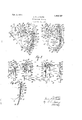
Figure 3 is a front view of the device as shown in Figure 2.
Figure 4 is a vertical section, showing the detailed structure of the stencil-holder.
A carriage 10 is mounted in the usual manner upon front and rear rails (not shown), and comprises a frame having end walls 11 and 12 connected at their lower ends by a tie-rod 13 and at their upper ends by a tie-strap 14 and a tie-rod 21. A short platen 15 is mounted upon an axle or shaft 16, journaled in the end walls 11 and 12,
said shaft being rotatable b knobs or finger-wheels 17 fixed to, the on s thereof, or by the usual line-spacing mechanism comprismg a handle 18 operating a slide 19, having a pawl (not shown) which meshes with a ratchet 20 fixed to the shaft. The platen is enclosed between side plates and 26 fixed at their upper endsto the tie-strap 14an'd connected at their lower ends by a tie-rod 27.
The stencil-holder, which is fed upwardly and downwardly in front of the platen by means to be hereinafter described, comprises dependin fingers 30 and 31 having inturned lower en s 32, forming hooks or pockets for supporting a stencil-frame at its lower edge, and havin inturned side flanges 33 to hold the stenci -frame at its side edges against sidewise movement. Spring-clips 22 are fixed one to each finger at the front face thereof, and project rearwardly through slots 24 in the fingers,'the clips terminating in horizontal projections 23 which overlie the upper edge of a stencil-frame and prevent upward movement thereof. The depending fingers 30 and 31 are provided at their upper ends with side extensions 35 and 36 by means of which they are fixed to a cross-bar 37. The stencil-holder is movable upwardly and downwardly in front of the platen by racks 40 and 41, fixed to the ends of the cross-bar 37 and meshing with gearwheels 42 and 43 fixed to the shaft 16 to be rotated integrally therewith. It is therefore obvious that rotation of the shaft by the finger-Wheels 17 or by the line-space handle will raise or lower the racks, and hence the depending fingers which support the stencil-frame. The racks are held in mesh with their respective gear-wheels by plates 44, fixedly mounted upon the shaft 16 adjacent each ear-wheel and having flanges 45 which enc ose the racks and maintain them in engagement with the gear-wheels.
It is desirable to guide the stencil-frame so that its upper edge will be pressed back wardly to give the frame a slight curvature at the printing point, indicated generally by the ty e-head 50. For this purpose, there is PI'OVI' ed, firstly, a projection 51 on each finger 30, 31, which presses the upper edge of astencil-frame 52 backwardly, and, since thelower edge of the frame .is held in pockets 32, the frame will be slightlycurved about the platen. To hold the frame against ,are given a slight curvature.
movement, the spring-detents or clips 22, fixed to the fin ers 30 and 31 and 'rojectin therethrough, ave substantially orizonta flanges which abut against the upper edge of the frame, as previously described. The slightly curved relation of the frame to the platen is attained, secondly, by guiding the movement of cross-bar 37 slightly rearwardly by means of pins 60 operating in arcuate, rearwardly directed slots 61 in members 62 having flanges 63 fixed to the endwalls 11 and 12 by screws 64. It is apparent that the depending fingers 30 and 31 have their upper ends inclined normally forwardly. By directing the cross-bar 37, and hence the upper ends of fingers 30 and 31, rearwardly as described above, the fingers The projections 51 give the stencil-frame an additional rearward curvature, so that, although the frame is not bent sufficiently to crack or typed upon the stencil.
otherwise injure it, it nevertheless conforms to the curvature of the platen at the printing point suijiciently to enable the types to make a c ear impression on the stencil.
It is frequently desirable to employ stencil-frames of different widths. For this purpose, one of the depending fingers (here shown as "31) is mounted for lateral adjustment on the cross-bar 37, the latter being provided with additional sets of openings 65 through which pass the fastening members.
In order to make the stenciling visible, an ink-ribbon 69 may be provided at the rear of the stencil between the stencil and the platen. The ribbon mechanism illustrated is more particularly described and claimed in the co-pending ap lication of Alfred G. F. Kurowski, Serial 180. 459,964, filed April 9, 1921. The ribbon is led from one of two ribbon- rolls 70 and 71, mounted upon short shafts 72 and 73, projecting inwardly from the side plates 25, 26 around the platen to the other of said rolls. The ribbon is fixed at each end upon a ribbon-spool mounted upon the short shafts between flanges 75, 76, fixed near the end of each shaft, said spools being readily replaceable due to the fact that one of the shafts upon which each spool is mounted may be withdrawn laterally against the action of a spring 79 by a knob 80, fixed to the respective shaft.
It is desirable to feed the ribbon past the printing point simultaneously with the linefeeding of the stencil so that a fresh ribbon surface is presented to each succeeding line The movement of the ribbon is accomplished by fixing a ratchet 81, 82, to each roll 70, 71, adj acentone of the sidelates, one of said ratchets being operated y a pawl-member 83 pivoted at one end of a lever 84, said lever being connected by a link 85 to an arm 86 formed upon a hub 87, fixed to the shaft 16, so that rotation of the shaft in line-feeding direction will rotate arm 86 upwardly and actuate the pawl-member downwardly to drive one of the ratchets and wind the ribbon on the corresponding roll. Upon the return movement of the shaft and its attached arm, the pawl-member will not operate the ribbon-rolls, the pawl riding idly over the ratchets. It is apparent that, after a sufiicient number of stencils have been typed, the ribbon will be completely wound upon one of the rolls 70, 71, with which the ratchet is in engagement. The ribbon is capable of further use, and hence means are provided for moving the pawl-member into engagement with the other ratchet, so that further line-feeding of the platen winds the roll which had previously been unwound, and this avoids the necessity of manually rewinding the ribbon. For this purpose, pawl-member 83 is provided with two pawls 90, 91, for co-operation with ratchets 81 and 82, respectively, the
pawl-member being swung about its pivot into engagement with one or the other of, sald ratchets depending upon which roll it is desired to wind. The pawl-member is held in engagement with either ratchet, as desired, by a spring-detent in the form of a lever 92, pivoted upon lever 84, and having its upper end pressed by a spring 93, connected at its lower end, into either of two notches 94 and 95 in the pawl-member to hold said member in engagement with ratchets 81 and 82, respectively.
Variations may be resorted to within the scope of the invention, and portions. of the improvements may be used without others.
Having thus described my invention, I claim:
1. In a typewriting machine, the comb-ination with a revoluble platen, of a stencilholder comprising a pair of fingers, and means on said fingers for holding a stencilframe at its bottom edge, said fingers having raised portions to bend the upper part of the stencil-frame rearwardly, and rearward projections engaging the upper edge of said stencil-frame to hold said frame against upward movement in said holder.
2. -In a typewriting machine, the combination with a revoluble platen, of a stencilholder comprising a pair of resilient fingers adapted to be bent and thereby to cause the stencil to be bent at the line of writing, and means on said fingers for holding a stencilframe at its bottom edge, said fingers hav ing side flanges for guiding said stencilframe at its side edges to prevent sidewise movement thereof.
3. In a typewriting machine, the combination with a revoluble platen, of a stencilholder comprising a pair of fingers, and means on said fingers for holdinga stencilframe at its bottom edge, said fingers having rearwardly projecting spring-clips forming abutments for positively intercepting the upper edge of said stencil-frame to hold said stencll-frame against upward movement in said holder.
4. In a typewriting machine, the combination with a revoluble platen, of a stencilholder movable to fee-d the stencil to the frame comprising a pair of fingers, means on said fingers for holding a stencil-frame at its bottom edge, said fingers each having a slot therein, and spring-clips fixed to the front face of said fingers and projecting rearwardly through said slots, said clips engaging the upper edge of said stencilframe to hold said stencil-frame against upward movement relatively to the holder.
5. In a typewriting machine, the combina tion with a revo-luble platen, of a stencilholder comprising a pair of fingers, means for moving the stencil-holder to feed the stencil, and means on said fingers for holding a stencil-frame at its bottom edge, said fingers having rearward projections for preventing sidewise and upward movement of said frame relatively to the holder.
6. In a typewriting machine, the combination with a revolub-1e platen, of a stencilholder comprising a pair of fingers, and means on said fingers for holding a stencilframe at its bottom edge, said fingers having side flanges for guiding said stencil-frame at its side edges to prevent sidewise movement thereof, said fingers having also rearward projections engaging the upper edge of said stencil-frame at an angle such that the projections will hold it positively against upward movement in said holder.
7. In a typewriting machine, the combination with a revoluble platen, of a stencilholder comprising a pair of fingers, asupport for said fingers, and means on said fingers for holding a stencil-frame at its bottom edge, said fingers being relatively adjustable laterally of said support to vary the distance between the fingers, thereby to enable them to uide stencil-frames of different widths without obstructing the writing surfaces of the stencils;
8. In a typewriting machine, the combination with a revoluble platen, of a stencilholder comprising a pa1r of'fingers, a support for said fingers, means on said fingers for holding a stencil-frame at its bbttom edge, and means whereby one of said fingers may be adjusted laterally along said support and fixed thereto at various points to vary the distance between the fingers for accommodating stencil-frames of different widths.
9. In a typewritin machine, the combination with a revolub e platen, of a stencilholder for maintaining the stencil in fixed relation to itself comprising a pair of fingers, and means on said fingers for supporting a stencil-frame at its bottom edge, each of said fingers having a portion of its surface formed into a rearward projection near the upper edge of said stencil-frame for forcing the upper edge of said stencilframe rearwardly to curve said stencilframe around the platen.
10. :In a typewritin machine, the combination with a revolub e platen, of a stencilholder movable to feed the stencil through the machine comprising a pair of fingers, and means on said fingers for engaging a stencil-frame at its bottom edge, each of said fingers having an integral rearward projection near the upper edge of said stencilframe for forcing the upper edge of said stencil-frame rearwardly to curve said stencil-frame around the platen.
11. In a typewriting machine, the combination with a platen-frame having a revolubleplaten journaled therein, of a stencil holder comprising a pair of fingers, means on said fingers for holding a stencil-frame at its bottom edge, members fixed to said platen-frame, one at eaclr end thereof, and each having an arcuate cam-slot which extends gradually rearwardly throughout its length, a support for said fingers having its ends operating in said slots, and means for line-feeding said support and stencilholder upwardly, said support moving gradually and constantly rearwardly in said slots as it moves upwardly to move the upper ends of said fingers gradually rearwardly for curving the stencil-frame substantially uniformly around the platen.
12. In a typewriting machine, the combination with a platen-frame having a revoluble platen journaled therein, of a, stencilholder comprising a pair of fingers, means on! said fingers for holding a stencil-frame at'its bottom edge, members fixed to saidplaten-frame, one at each end thereof, and each having an arcuate cam-slot which extends gradually rea-rwardlv throughout its length, a support for said ngers having its ends operating in said slots, means for linefeeding said support and stencil-holder upwardly, said support moving gradually and constantly rearwardly in said slots as it moves upwardly to move the upper ends of said fingers gradually rearwardly for curving the stencll-frame around the platen, and rearward projections on said fingers near the upper edge of said stencil-frame for forcing the upper edge of said frame rearwardlyr and curving said frame an additional amount around the platen.
JESSE A. B. SMITH. Witnesses:
EDITH B. LIBBEY, JENNIE P. THORNE.
Priority Applications (1)
| Application Number | Priority Date | Filing Date | Title |
|---|---|---|---|
| US462890A US1450737A (en) | 1921-04-20 | 1921-04-20 | Typewriting machine |
Applications Claiming Priority (1)
| Application Number | Priority Date | Filing Date | Title |
|---|---|---|---|
| US462890A US1450737A (en) | 1921-04-20 | 1921-04-20 | Typewriting machine |
Publications (1)
| Publication Number | Publication Date |
|---|---|
| US1450737A true US1450737A (en) | 1923-04-03 |
Family
ID=23838143
Family Applications (1)
| Application Number | Title | Priority Date | Filing Date |
|---|---|---|---|
| US462890A Expired - Lifetime US1450737A (en) | 1921-04-20 | 1921-04-20 | Typewriting machine |
Country Status (1)
| Country | Link |
|---|---|
| US (1) | US1450737A (en) |
Cited By (1)
| Publication number | Priority date | Publication date | Assignee | Title |
|---|---|---|---|---|
| US3139169A (en) * | 1960-09-21 | 1964-06-30 | Monroe Calculating Machine | Printing machine record sheet holder |
-
1921
- 1921-04-20 US US462890A patent/US1450737A/en not_active Expired - Lifetime
Cited By (1)
| Publication number | Priority date | Publication date | Assignee | Title |
|---|---|---|---|---|
| US3139169A (en) * | 1960-09-21 | 1964-06-30 | Monroe Calculating Machine | Printing machine record sheet holder |
Similar Documents
| Publication | Publication Date | Title |
|---|---|---|
| US2240578A (en) | Typewriting machine | |
| US1450737A (en) | Typewriting machine | |
| US1682333A (en) | Typewriting machine | |
| US2214415A (en) | Typewriting machine | |
| US1198638A (en) | Type-writing machine. | |
| US1741664A (en) | Typewriting machine | |
| US1446976A (en) | Typewriting machine | |
| US1741545A (en) | Typewriting machine | |
| US2165301A (en) | Typewriting machine | |
| US1386969A (en) | Typewriting-machine | |
| US1463478A (en) | Multicopy writer | |
| US1455496A (en) | Typewriting machine | |
| US1853303A (en) | Manifolding device | |
| US1705946A (en) | Typewriting machine | |
| US1424905A (en) | Typewriting machine | |
| US1030453A (en) | Type-writing machine. | |
| US1102752A (en) | Type-writing machine. | |
| US1394632A (en) | Henky n | |
| US1293252A (en) | Type-writing machine. | |
| US1624697A (en) | Typewriting machine | |
| US1300905A (en) | Type-writing machine. | |
| US2074778A (en) | Typewriter | |
| US1447990A (en) | Typewriting machine | |
| US1082104A (en) | Ribbon mechanism for type-writing machines. | |
| US1654901A (en) | Typewriting machine |