US1440366A - Apparatus for assembling bricks and units for building purposes - Google Patents
Apparatus for assembling bricks and units for building purposes Download PDFInfo
- Publication number
- US1440366A US1440366A US551442A US55144222A US1440366A US 1440366 A US1440366 A US 1440366A US 551442 A US551442 A US 551442A US 55144222 A US55144222 A US 55144222A US 1440366 A US1440366 A US 1440366A
- Authority
- US
- United States
- Prior art keywords
- units
- bricks
- unit
- assembling
- brick
- Prior art date
- Legal status (The legal status is an assumption and is not a legal conclusion. Google has not performed a legal analysis and makes no representation as to the accuracy of the status listed.)
- Expired - Lifetime
Links
- 239000011449 brick Substances 0.000 title description 44
- 239000004570 mortar (masonry) Substances 0.000 description 12
- 230000015572 biosynthetic process Effects 0.000 description 10
- 238000007789 sealing Methods 0.000 description 10
- 125000006850 spacer group Chemical group 0.000 description 10
- 239000004568 cement Substances 0.000 description 6
- 238000000034 method Methods 0.000 description 5
- 238000010276 construction Methods 0.000 description 2
- 239000002184 metal Substances 0.000 description 2
- 239000004160 Ammonium persulphate Substances 0.000 description 1
- 229910000831 Steel Inorganic materials 0.000 description 1
- 238000004873 anchoring Methods 0.000 description 1
- 239000011230 binding agent Substances 0.000 description 1
- OFZCIYFFPZCNJE-UHFFFAOYSA-N carisoprodol Chemical compound NC(=O)OCC(C)(CCC)COC(=O)NC(C)C OFZCIYFFPZCNJE-UHFFFAOYSA-N 0.000 description 1
- 239000003795 chemical substances by application Substances 0.000 description 1
- VKYKSIONXSXAKP-UHFFFAOYSA-N hexamethylenetetramine Chemical compound C1N(C2)CN3CN1CN2C3 VKYKSIONXSXAKP-UHFFFAOYSA-N 0.000 description 1
- 239000011505 plaster Substances 0.000 description 1
- 239000010959 steel Substances 0.000 description 1
Images


Classifications
-
- E—FIXED CONSTRUCTIONS
- E04—BUILDING
- E04C—STRUCTURAL ELEMENTS; BUILDING MATERIALS
- E04C2/00—Building elements of relatively thin form for the construction of parts of buildings, e.g. sheet materials, slabs, or panels
- E04C2/02—Building elements of relatively thin form for the construction of parts of buildings, e.g. sheet materials, slabs, or panels characterised by specified materials
- E04C2/04—Building elements of relatively thin form for the construction of parts of buildings, e.g. sheet materials, slabs, or panels characterised by specified materials of concrete or other stone-like material; of asbestos cement; of cement and other mineral fibres
- E04C2/041—Building elements of relatively thin form for the construction of parts of buildings, e.g. sheet materials, slabs, or panels characterised by specified materials of concrete or other stone-like material; of asbestos cement; of cement and other mineral fibres composed of a number of smaller elements, e.g. bricks, also combined with a slab of hardenable material
-
- E—FIXED CONSTRUCTIONS
- E04—BUILDING
- E04C—STRUCTURAL ELEMENTS; BUILDING MATERIALS
- E04C2/00—Building elements of relatively thin form for the construction of parts of buildings, e.g. sheet materials, slabs, or panels
- E04C2002/001—Mechanical features of panels
- E04C2002/004—Panels with profiled edges, e.g. stepped, serrated
Definitions
- BALDWIN a citizen of the United States, residing at South Greensburg, in the county ot Westmoreland and State of Pennsylvania, have invented new and useful improvements in Apparatus for Assembling Bricks and Units for Building Purposes, of which the following is a specifica-tion.
- lt is also my purpose; to provide a method et' andapparatus tor assembling bricks in units for building purposes by -means of which the average layman may erect a house or other structure in' less time and with as much facility as a brick layer or other skilled mechanic.
- l aim to provide a method cost and which will enable the average layman to erect a brick structure without 'training.
- Another object of my invention is thel provision ont a method of and apparatus Jtor yassemblingy bricks in units whereby the joints formed by the mortar at the face of the brick may be made in any shape or formation so that the desired ornamental etiect may be given to the face of the wall or structure soV Vl/Vith the above recited objects in view, and others of va like nature, the invention resides in the construction, combination and arrangement lof parts set forth in land ⁇ tallingwithin the scope of the appendedclaims.
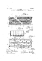
- Figure 2 is a plan View of the form used for assembling the bricks in unit formation.
- F igurev 3 is a sectional View on the line 3-.3 of Figure 2.
- FIG. 4C is a plan view or the form showing the bricks and end pieces in place.
- Figure 5 is a sectional View on the Aline 5-5 of Figure 4f.
- Figure 6 is a plan view of one of the' end pieces.
- Figure 7 is a top plan view of the form used for erecting chimneys, pillars, etc.
- Figure 8 is a cross sectionalview on the line 88 of Figure 7.
- Figure 9 is a fragmentary vertical sectional view through the bricks assembled and anchored to sheathing.
- ligure 10 is a' perspective ⁇ view ot one of the'anchor plates Jfor anchoring the brick unit to the sheathing.
- Figure 11' is a fragmentary perspective view or' a brick unit.
- figure 12 isa similar view showing the unit inverted so as to properly connectwith the unit shown in Figure 11.
- Figure 13 is a. perspective view ot a spacing block that may be used if desired.
- Figure 14e is a side elevation of two bricks showing a spacer therebetween.
- Figure 15 is a. perspective view of the spacer used in' Figure 1li and in assembling the bricks in unit formation.
- Figure 16 is a cross sectional view showing two forms of joint forming elements for use in the form.
- Figure 17 is a perspective view of a detail of the invention.
- FIGS 18, 19, 20and 21 are perspective views of various details of the invention.
- A. indicates a chart which 1 propose to furnish to those who build according to my invention and on which is depicted-the structure that is to be erected.
- the present instance l have shown a wall that is composed of units B and C. each unit being ⁇ formed and then set into place and sealed to the companion units b v mortar or cement as are the bricks offeach unit.
- the units n are inverted to the units B in order that a smooth unbroken surface will be presented.
- provision is made for door and window openings' and suchothcx apertures as may be necessary or desired in the erectionof the building or other structure, as shown at D in Figure 1, provision being also made for sills, abutments, etc.
- each unit I employ a form 1 embodying a bottom wall 2, side walls 3, end walls 4 and end sections orpieces 5 which are detachably secured to the side walls 3 as is more fully described hereinafter.
- This form is of such len th that a desired number of units may be ormed therein simultaneously and in Figure 2 I have shown a form wherein two units may be assembled, one being what I term an end unit and the other a central unit.
- One end of the end unit form is closed by the straight end wall 4 and the other end is closed by the end piece or section 5, while both ends of xi'the' central unit are closed by the end sections or pieces 5, as shown in Figure 4.
- Each end section 5 comprises a sheet or strip of metal which is stepped as at 6 so that the end bricks in each row of the unit may be uniformly stepped in order to properly overlie the next lower brick in the companion section when the sections are set up in structure formation, as indicated on the chart in Figure 1.
- the stepped bricks of the units B and the relatively-long surfaces of the units C form top surfacesofthe units: i4 e. extend skyward and these skyward surfaces of the units are formed with sealing pockets so that all of the units may be securely and properly sealed togetherin the erection of -the structure.
- each end section are formed with outturned lugs 8 equipped with bolts 9 that project through openings in the side walls 3 and are provided with locking nuts 10 by means of which the sections 5 may be locked in position in the form and whereby vthe sections 5 may be lreleased when it is desired to, remove the sections from the form.
- sealing pocket forming means which, in the present instance,are in the form of blocks 7 each of less cross and lon itudinal dimensions than the adjacent sur ace of the brick.
- the unit may be assembled with other units to erect the desired structure.
- the spacers Before the binding agent-sets the spacers are withdrawn and after the mortar has hardenedl the end pieces 5 are released and removed.
- sealing pocket forming blocks 7, sealingpockets 11, cle'arly shown in Figures 11 and 12, are provided in the skyward surfaces of the units.
- These pockets 11 are lled with cement, ⁇ mortar or other bind- 'ing agent in the erection of the structure,
- Figures 7 and 8 I have shown a form for the building of units that may/.be em-i ployed in the erection of chimneys, columns, etc., and in the present embodiment this form comprises a core 18 and an outer casing 19 between which and the core the bricks are placed iny rows one upon the other-with mortar, cement or thelv like between the rows to bind the saine in unit formation. 0n the Atop row is the" sealing Vpocket forming strip 20.
- the 'oint forming strips may bev of any desired shape and in the use of the joint forming strip the latter is placed upon the bottom4 wall 2 .of the form, as shown'in l Figures 2 and 3, in order that a mortar joint of the'desired -ormamenta-- ⁇ tion maybe formed on the face. of the brick unit.
- Figure 18 l have shown a spacer that is used in connection with my apparatus for assembling bricks in units, andin this form of my invention the spacer comprises a' substantially rectangular shaped metal strip j 23 formed at its corners with upstanding inverted l#shaped portions 2t. rllhis spacer is used when it is desired to make provision for lattice work around porches, etc.
- This spacer and mortar relase is similar in construction to the ceiling pocket forming piece 7 hereinbefore described and is designed for use upon the skyward surfaces of the units that are formed for columns, chimneys, etc.
- this combination joint spacer and mortar release comprises a spacing block 25 formed at one edge centrally of the ends of such edge with a tongue 26 and provided on its upper surface with pins 27
- the tongue 26 terminates flush with the outer surface of the brick and after the cement has hardened a release opening is provided, as shown in Figure 11, so that when the companion unit is set on the lower unit the mortar within the sealing pocket may be pressed downwardly and forced out through the release vopening formed by the tongue 26 and then
- Figure 21 l have shown a steel strikeed piece 30 which is to be utilized when one surface of the brick unit is to be faced with plaster.
- Athat l have provided ⁇ a method and means whereby brick units ma be built up and vsubsequently assembled, an whereby sealing pockets may be formed in the units so that in the assembling of the units each may be securely sealed or fastened to the other and whereby mortar joints on the face of the brick may be formedin -such manner as to give the desired ornamental appearance.
- a form for assembling bricks in unit an end piece stepped toffit the corresponding end of the unit, means carried by said end piece to form sealing pockets on those surfaces of the bricks that face skyward,
Landscapes
- Engineering & Computer Science (AREA)
- Architecture (AREA)
- Civil Engineering (AREA)
- Structural Engineering (AREA)
- Conveying And Assembling Of Building Elements In Situ (AREA)
Description
@www
Mmm@
wmmrus Fora Assfamaumemcxs AND Umfs FcR Sanoma' PURPQSES FILED APR. 11 192g. y 5l SHEETS- swear 2 il Y ooo@ im imno-51 50-'61 @o 00Goo Moewig- 610 mmm @im com c f. ,M7 Mm.
www@
Jamo 29 E923, -V H. A. BALDWIN.
APPARATUS-FOR ASSEMBLING BRIcKs ANI: UNITS FoR BUILDING PuRPosEs.
FILED APR. 1l. i922. 5 SHEETS-SHEET 3 Ir. I A r.
im@ 11923. www@ H. A. BALDWIN. APPARATUS Fon ASSEMBLING Bmcxs AND UNxTs FoR BUILDING PunPosEs.
' Fuso APR. 11. 1922. 5 SHEETS-SHEET 4 am, lg 31944699366 H. A. BALDWIN. y
APPARMUS Fon Assmann@ BRICK; AND UNlsA Fon BUILDING PuRPusEs.
Fumo AFR. H. 1922, 5 swans-SHEET 5 INVENTOR.
ATTORNEY.
y /5 By I Patented Jan.. 2.1@23
nnTTsn sTaTjes llpttlttt PATENT cerros.'
APPARATUS FOR' ASSEMBLENG BRICKS Application led April 11,
To all 'who/m, it may concern Be it known that l, HARRY A. BALDWIN, a citizen of the United States, residing at South Greensburg, in the county ot Westmoreland and State of Pennsylvania, have invented new and useful improvements in Apparatus for Assembling Bricks and Units for Building Purposes, of which the following is a specifica-tion. I
In carrying out the present invention it is my purpose to provide a method ot and apparatus for assembling bricks in units in such manner that the units may be assembled together to form Aa wall or other structure, and whereby the various units when assembled and associated togetherl in structure formation will be effectively connected or sealed together so as to form a structure having the appearance of a wall or struc# ture erected in the ordina-ry manner.
lt is also my purpose; to provide a method et' andapparatus tor assembling bricks in units for building purposes by -means of which the average layman may erect a house or other structure in' less time and with as much facility as a brick layer or other skilled mechanic.
Furthermore, l aim to provide a method cost and which will enable the average layman to erect a brick structure without 'training. Y l
Another object of my invention is thel provision ont a method of and apparatus Jtor yassemblingy bricks in units whereby the joints formed by the mortar at the face of the brick may be made in any shape or formation so that the desired ornamental etiect may be given to the face of the wall or structure soV Vl/Vith the above recited objects in view, and others of va like nature, the invention resides in the construction, combination and arrangement lof parts set forth in land `tallingwithin the scope of the appendedclaims.
ln the accompanying drawings:
Figur-e1 is a plan view of a chart by which my inventionmay be carried out.
Figure 2 is a plan View of the form used for assembling the bricks in unit formation.
am) Unrrs non surnnrne rmarosiss.
i922. serial no. 551,442.
F igurev 3 is a sectional View on the line 3-.3 of Figure 2.
t Figure 4C is a plan view or the form showing the bricks and end pieces in place.
= Figure 5 is a sectional View on the Aline 5-5 of Figure 4f.
Figure 6 is a plan view of one of the' end pieces.
Figure 7 is a top plan view of the form used for erecting chimneys, pillars, etc.
Figure 8 is a cross sectionalview on the line 88 of Figure 7.
Figure 9 is a fragmentary vertical sectional view through the bricks assembled and anchored to sheathing.
ligure 10 is a' perspective `view ot one of the'anchor plates Jfor anchoring the brick unit to the sheathing.
Figure 11' is a fragmentary perspective view or' a brick unit.
figure 12 isa similar view showing the unit inverted so as to properly connectwith the unit shown in Figure 11.
Figure 13 is a. perspective view ot a spacing block that may be used if desired.
Figure 14e is a side elevation of two bricks showing a spacer therebetween.
Figure 15 is a. perspective view of the spacer used in'Figure 1li and in assembling the bricks in unit formation.
Figure 16 is a cross sectional view showing two forms of joint forming elements for use in the form.
Figure 17 is a perspective view of a detail of the invention.
Figures 18, 19, 20and 21 are perspective views of various details of the invention.
Referring now to the drawings in detail., and particularly to Figure 1, A. indicates a chart which 1 propose to furnish to those who build according to my invention and on which is depicted-the structure that is to be erected. lln the present instance l have shown a wall that is composed of units B and C. each unit being` formed and then set into place and sealed to the companion units b v mortar or cement as are the bricks offeach unit. 'It will be noticed that the units n; are inverted to the units B in order that a smooth unbroken surface will be presented. Of course provision is made for door and window openings' and suchothcx apertures as may be necessary or desired in the erectionof the building or other structure, as shown at D in Figure 1, provision being also made for sills, abutments, etc.
In order to construct each unit I employ a form 1 embodying a bottom wall 2, side walls 3, end walls 4 and end sections orpieces 5 which are detachably secured to the side walls 3 as is more fully described hereinafter. This form is of such len th that a desired number of units may be ormed therein simultaneously and in Figure 2 I have shown a form wherein two units may be assembled, one being what I term an end unit and the other a central unit. One end of the end unit form is closed by the straight end wall 4 and the other end is closed by the end piece or section 5, while both ends of xi'the' central unit are closed by the end sections or pieces 5, as shown in Figure 4. l
Each end section 5 comprises a sheet or strip of metal which is stepped as at 6 so that the end bricks in each row of the unit may be uniformly stepped in order to properly overlie the next lower brick in the companion section when the sections are set up in structure formation, as indicated on the chart in Figure 1. As shown on the chart the stepped bricks of the units B and the relatively-long surfaces of the units C form top surfacesofthe units: i4 e. extend skyward and these skyward surfaces of the units are formed with sealing pockets so that all of the units may be securely and properly sealed togetherin the erection of -the structure. The ends of each end section are formed with outturned lugs 8 equipped with bolts 9 that project through openings in the side walls 3 and are provided with locking nuts 10 by means of which the sections 5 may be locked in position in the form and whereby vthe sections 5 may be lreleased when it is desired to, remove the sections from the form.
In order to form these sealing. pockets the side 3 of the form next to the skyward side of the unit and the end piece 5 next to the sk'yward eindl of the unit are provided with sealing pocket forming means which, in the present instance,are in the form of blocks 7 each of less cross and lon itudinal dimensions than the adjacent sur ace of the brick. j
In the practice of my invention the brick.; are placed in the form with the face down and lie upon the bottom wall 2. The end the side wall 3 that lies adjacent'to the sky? wardz surface of the.unit's,'as clearly illustrated in Figure 4. The'bricks. in each unit are now properly spaced apart so as'to reeive the cement or mortar andl to so s acey the bricks I employ spacers, .shown in ig bricks vare securely held in unit formation.
'and the unit may be assembled with other units to erect the desired structure." Before the binding agent-sets the spacers are withdrawn and after the mortar has hardenedl the end pieces 5 are released and removed.
from the form and the units taken out, and
owing tothe sealing pocket forming blocks 7, sealingpockets 11, cle'arly shown in Figures 11 and 12, areprovided in the skyward surfaces of the units. These pockets 11 are lled with cement, `mortar or other bind- 'ing agent in the erection of the structure,
and the units then placed in proper fitting engagement with one another, as shown on the chart A, andthe binding agent in the pockets acts to hold the units in structure formation.
If it is desired to secure the units to sheathing S so that a frame'structure lmay\ bricks of the unit and are fastened to the sheathing as illustrated in Figures 9 and 1()l of the drawings. f I
In Figures 7 and 8 I have shown a form for the building of units that may/.be em-i ployed in the erection of chimneys, columns, etc., and in the present embodiment this form comprises a core 18 and an outer casing 19 between which and the core the bricks are placed iny rows one upon the other-with mortar, cement or thelv like between the rows to bind the saine in unit formation. 0n the Atop row is the" sealing Vpocket forming strip 20.
In Figure 16 Ihave shown two forms of 'oint formin strips 21.
e unders that the 'oint forming strips may bev of any desired shape and in the use of the joint forming strip the latter is placed upon the bottom4 wall 2 .of the form, as shown'in lFigures 2 and 3, in order thata mortar joint of the'desired -ormamenta--` tion maybe formed on the face. of the brick unit.
In Figure 13 I have shown one form of spacing plate that may be used -inthe event that it isv desired to hold the bricks spaced f apart' from the bottom of the; form for any reason, Aas when it is desired .to make pro- It will of courseV Macnee end wall 4 is hinged as at 22, so that the said Wall may be swung out'from the form if found necessary.
ln Figure 18 l have shown a spacer that is used in connection with my apparatus for assembling bricks in units, andin this form of my invention the spacer comprises a' substantially rectangular shaped metal strip j 23 formed at its corners with upstanding inverted l#shaped portions 2t. rllhis spacer is used when it is desired to make provision for lattice work around porches, etc.
ln Figure 20 ll'have shown what li term a combined joint spacer and mortar release which is preferably used in forming columns, chimneys, etc. This spacer and mortar relase is similar in construction to the ceiling pocket forming piece 7 hereinbefore described and is designed for use upon the skyward surfaces of the units that are formed for columns, chimneys, etc. ln the present instance this combination joint spacer and mortar release comprises a spacing block 25 formed at one edge centrally of the ends of such edge with a tongue 26 and provided on its upper surface with pins 27 When theblock 25 is set in posi-v tion on the unit previous to the pouring of the cement or mortar, the tongue 26 terminates flush with the outer surface of the brick and after the cement has hardened a release opening is provided, as shown in Figure 11, so that when the companion unit is set on the lower unit the mortar within the sealing pocket may be pressed downwardly and forced out through the release vopening formed by the tongue 26 and then In Figure 21 l have shown a steel strikeed piece 30 which is to be utilized when one surface of the brick unit is to be faced with plaster.
From 'the foregoing description, taken in connection'with the accompanying drawings, it will be seen Athat l have provided `a method and means whereby brick units ma be built up and vsubsequently assembled, an whereby sealing pockets may be formed in the units so that in the assembling of the units each may be securely sealed or fastened to the other and whereby mortar joints on the face of the brick may be formedin -such manner as to give the desired ornamental appearance.
lt claim: l p
l.. A form for assembling bricks in unit formation with the ends of the rows of bricks at one end of the form stepped, comprising a bottom wall upon wliichthe bricks are adapted to be placed with the face down, an end piece stepped to fit the corresponding end of the unit, and means carried by said end piece to form sealing pockets on those surfaces of the bricks that face skyward. t 2. A form for assembling bricks in unit an end piece stepped toffit the corresponding end of the unit, means carried by said end piece to form sealing pockets on those surfaces of the bricks that face skyward,
and a detachable connection between said.
end piece and the form.
3. A form for assembling bricks in unit formation with the ends of the rows of bricks at one'end of the form stepped, com prising a bottom Wall upon which the bricks are adapted to be placed with the -face' down, an end piece stepped to fit the corresponding end .of the unit, means carried by said end piece to form sealing pockets on ward, and a detachable and adjustable con! nection between said end piece and said form.-
ln testimony whereof l aiix my signature.
HARRY A.. BALDWIN.
lthose surfaces of the bricks that face sky-
Priority Applications (1)
| Application Number | Priority Date | Filing Date | Title |
|---|---|---|---|
| US551442A US1440366A (en) | 1922-04-11 | 1922-04-11 | Apparatus for assembling bricks and units for building purposes |
Applications Claiming Priority (1)
| Application Number | Priority Date | Filing Date | Title |
|---|---|---|---|
| US551442A US1440366A (en) | 1922-04-11 | 1922-04-11 | Apparatus for assembling bricks and units for building purposes |
Publications (1)
| Publication Number | Publication Date |
|---|---|
| US1440366A true US1440366A (en) | 1923-01-02 |
Family
ID=24201280
Family Applications (1)
| Application Number | Title | Priority Date | Filing Date |
|---|---|---|---|
| US551442A Expired - Lifetime US1440366A (en) | 1922-04-11 | 1922-04-11 | Apparatus for assembling bricks and units for building purposes |
Country Status (1)
| Country | Link |
|---|---|
| US (1) | US1440366A (en) |
Cited By (9)
| Publication number | Priority date | Publication date | Assignee | Title |
|---|---|---|---|---|
| US2428374A (en) * | 1944-02-24 | 1947-10-07 | Ernest G Malthouse | Erection of brickwork structures |
| US2472221A (en) * | 1944-05-09 | 1949-06-07 | Malthouse Ernest Goodall | Erection of brickwork structures |
| US2630702A (en) * | 1950-07-27 | 1953-03-10 | Pizzani Valentine | Tile set tool |
| US2797495A (en) * | 1955-11-08 | 1957-07-02 | Everett V Walston | Glass building block aligner |
| US3010213A (en) * | 1958-09-24 | 1961-11-28 | Sr Robert J Rodtz | Tile spacer |
| US3260493A (en) * | 1963-11-07 | 1966-07-12 | George S Beckham | Concrete form |
| US3290712A (en) * | 1965-05-11 | 1966-12-13 | Richey James | Combination trowel and gauge |
| US3519153A (en) * | 1967-04-21 | 1970-07-07 | Us Agriculture | Fiber blender (srrl bale-opener-blender) |
| FR2538294A2 (en) * | 1978-11-27 | 1984-06-29 | Martin Rafael | Pillar with visible stones |
-
1922
- 1922-04-11 US US551442A patent/US1440366A/en not_active Expired - Lifetime
Cited By (9)
| Publication number | Priority date | Publication date | Assignee | Title |
|---|---|---|---|---|
| US2428374A (en) * | 1944-02-24 | 1947-10-07 | Ernest G Malthouse | Erection of brickwork structures |
| US2472221A (en) * | 1944-05-09 | 1949-06-07 | Malthouse Ernest Goodall | Erection of brickwork structures |
| US2630702A (en) * | 1950-07-27 | 1953-03-10 | Pizzani Valentine | Tile set tool |
| US2797495A (en) * | 1955-11-08 | 1957-07-02 | Everett V Walston | Glass building block aligner |
| US3010213A (en) * | 1958-09-24 | 1961-11-28 | Sr Robert J Rodtz | Tile spacer |
| US3260493A (en) * | 1963-11-07 | 1966-07-12 | George S Beckham | Concrete form |
| US3290712A (en) * | 1965-05-11 | 1966-12-13 | Richey James | Combination trowel and gauge |
| US3519153A (en) * | 1967-04-21 | 1970-07-07 | Us Agriculture | Fiber blender (srrl bale-opener-blender) |
| FR2538294A2 (en) * | 1978-11-27 | 1984-06-29 | Martin Rafael | Pillar with visible stones |
Similar Documents
| Publication | Publication Date | Title |
|---|---|---|
| US1440366A (en) | Apparatus for assembling bricks and units for building purposes | |
| US2100451A (en) | Building construction | |
| US980480A (en) | Method for the construction of buildings. | |
| US2183450A (en) | Facing unit | |
| US2134637A (en) | Wall construction | |
| US2179407A (en) | Building block | |
| US1617033A (en) | Building construction | |
| US1537278A (en) | Molding device for constructing concrete walls | |
| US2241079A (en) | Building brick | |
| US1555433A (en) | Section for building up walls, ceilings, roofs, and the like | |
| US2739364A (en) | Building wall structure | |
| GB153973A (en) | Improvements in, or relating to, the construction of buildings | |
| US1375103A (en) | To jambs | |
| GB280832A (en) | Improvements in and relating to walls and roofs of portable buildings | |
| US1503110A (en) | Sectional roof | |
| US1702659A (en) | Wall-building form | |
| US1190977A (en) | Portable concrete-mold. | |
| US1583077A (en) | Nailing key for cement blocks | |
| GB456069A (en) | Improvements in or relating to building blocks, slabs, tiles or the like and structures made therefrom | |
| US1680781A (en) | Building block | |
| US1737526A (en) | Concrete building construction | |
| DE804957C (en) | Permanent formwork for walls | |
| GB338228A (en) | Improvements relating to building elements | |
| US1597240A (en) | Roof and floor construction | |
| US1397147A (en) | Floor construction |