US1417543A - Uncoupling mechanism - Google Patents
Uncoupling mechanism Download PDFInfo
- Publication number
- US1417543A US1417543A US505690A US50569021A US1417543A US 1417543 A US1417543 A US 1417543A US 505690 A US505690 A US 505690A US 50569021 A US50569021 A US 50569021A US 1417543 A US1417543 A US 1417543A
- Authority
- US
- United States
- Prior art keywords
- lock
- coupler
- uncoupling
- rotatable
- swinging
- Prior art date
- Legal status (The legal status is an assumption and is not a legal conclusion. Google has not performed a legal analysis and makes no representation as to the accuracy of the status listed.)
- Expired - Lifetime
Links
- XEEYBQQBJWHFJM-UHFFFAOYSA-N Iron Chemical compound [Fe] XEEYBQQBJWHFJM-UHFFFAOYSA-N 0.000 description 14
- 229910052742 iron Inorganic materials 0.000 description 7
- 241001474033 Acar Species 0.000 description 2
- 238000010276 construction Methods 0.000 description 2
- 238000012550 audit Methods 0.000 description 1
- 239000000969 carrier Substances 0.000 description 1
- 229940000425 combination drug Drugs 0.000 description 1
- 230000008878 coupling Effects 0.000 description 1
- 238000010168 coupling process Methods 0.000 description 1
- 238000005859 coupling reaction Methods 0.000 description 1
- 230000000694 effects Effects 0.000 description 1
Images
Classifications
-
- B—PERFORMING OPERATIONS; TRANSPORTING
- B61—RAILWAYS
- B61G—COUPLINGS; DRAUGHT AND BUFFING APPLIANCES
- B61G3/00—Couplings comprising mating parts of similar shape or form which can be coupled without the use of any additional element or elements
- B61G3/04—Couplings comprising mating parts of similar shape or form which can be coupled without the use of any additional element or elements with coupling head having a guard arm on one side and a knuckle with angularly-disposed nose and tail portions pivoted to the other side thereof, the nose of the knuckle being the coupling part, and means to lock the knuckle in coupling position, e.g. "A.A.R." or "Janney" type
- B61G3/06—Knuckle-locking devices
- B61G3/08—Control devices, e.g. for uncoupling
Definitions
- PENNSYLVANIA ASSIGNORS TO 'JTHE. McCONWAY -& wont-Er GOMPANY, 2 on A PITTSBURGH, PENNSYLVANIA, 'ACOR-PORATION or PENNSYLVANIA;
- Our invention relates to uncoupling mechanism for actuating the lock of a car coupler. WVhile' it is especially designed to afford uncoupling means well suited forapplication to the Master Car Builders standard 'D-type coupler employing a bottom operated lock, the invention may be embodied in uncoupling mechanism applicable to other forms of couplers as well.
- the primary object of the invention is to provide efficient, reliable and easily oper ated un'coupling'mechanism consisting of a few simple and compactly arranged parts.
- the principal feature-of the invention consists in actuating the lock of the coupler by means of a rotatable member whichhas a floating center of rotation and which slidably engages-means for causing it to perform an unlocking rotation.
- Another feature of the invention consists in moving the coup'ler'lock to unlocked position by means of arotatable member which is'caused to perform an unlocking'rotation by an actuating device'pivotally connected to a swinging support atthe center of rota tion of said rotatable member.
- Figure 1 is a View, partly in side eleva tion and partly in section, of an uncoupling mechanism embodying the invention, the car coupler shown being of the Master Car Builders Dtype.
- Figure "2 is a view,partly in side elevation well known Specification of Letters latcnt.
- Figure 3 is a detail sectional lview on the line 3+3, Fig.1, portionso'f'the uncoupling i levers and of the coupler-audits carrier iron being'broken away.
- Figures is a detail view, partly'in plan and partly in "horizontal section, of a porparts of the uncoution'of the mechanism, 'pllng levers belng broken away.
- F1gure5 a detail view of the. Inechanism partly 1n vertlcalsection'and partly in rearend elevation, a portion of the swinging supporting-meansand portions of the uncoupling levers being broken away.
- the car coupler l shownin the clrawings is of'the well known Master Car Builders D-type.
- alink 3- which-extends downwardly through the couplerhead and is pivotally connected at its'lower end to a u "hichisitself pivotally mounted upon the under side of the head of the coupler ⁇
- the link 3 and pivoted liftleve'r 4; preferably are Its'lock '2 is movably connectedto' swinging lift lever a constructed in accordance with the standard practice of the botto mlock lift devices of the i D-coupler.
- Therotatablelnember 6 may be convenientlyformed from a simple bar. It is adapted 'to be operated by'a member 9 swingingly"supported by a linklOto which it is pivotally connected at the center of rotation of the rotatable member 6.
- This mode of supporting the member 9 permits ed to cooperate with an eye 13 formed in the actuating member 9, and the upper hook 12 being adapted to book through a transversely elongated eye 14; formed on a coupler saddle 15, that is slidably supported on the coupler carrier iron 16 so as to be moved transversely of the car when the coupler 1 swings laterally.
- a coupler saddle 15 that is slidably supported on the coupler carrier iron 16 so as to be moved transversely of the car when the coupler 1 swings laterally.
- the coupler is intended to have a very wide range of lateral swing it may be advantageous to provide for the necessary lateral movement of the swinging support 10 by employing the transversely movable coupler saddle 15, as shown, rather than to support the link member 10 directly from the coupler carrier iron.
- the vertically rotatable member 6 extends through an aperture 17 formed in the swinging mem-' her 9 by which said rotatable member is caused to perform an unlocking movement.
- the actuating member 9 and the rotatable member slidably engage each other so that the latter may shift back and forth in response to draft and buffing movements of the coupler.
- the said member 9 is provided with a lug portion 18 extending under and adapted to engage the rotatable member 6, and to the rear of said center of rotation the member 9 is also provided with a portion 19 that extends over and is adapted to engage the opposite side of the rotatable member 0 lVhen the swinging member 9 is actuated. to effect an uncoupling operation its portions 18 and 19 simultaneously engage the member 6 so as to apply thereto oppositely directed forces compelling an unlocking rotation of the'latter.
- An unlocking movement of the swinging actuating member 9 is preferably effected from the sides of the car by means of a plurality of independently operating uncoupling levers 20.
- These levers may be of the well known form'illustrated in-the I. H. Milliken Patent No. 1,184,116, dated May 23 1916, except it is preferred that the bent inner ends 21 of said levers shall extend downsides with angular openings 22 permitting parts.
- tarmac swinging actuating member 9 is not required to move to so great an extent in order to permit compensation for the various angular positions which the rotatable member 6 may assume when the coupler swingslaterally.
- the swinging link device 10 In assembling the mechanismthe swinging link device 10 is turned laterally until it is at right angles to its normal position when transversely of the car. By this means the its hook 12 may be hooked through the transversely elongated eye 141 of the coupler saddle 15. The member 10 is then dropped to ordinary position, thereby becoming interlocked with the coupler saddleand thus preventing accidental disassociation of these The hook 7 of the rotatable member (3 is then engaged with the eye 8 of the lift lever apivoted to the coupler head. The swinging actuating'member 9 is' associated with the rotatable member 6 and is suspended from the member 10 by threading its eye 13 over the hooked lower end11 of the swinging support. The inner ends 21 of the uncoupling levers 20 are thereafter inserted. in the respective openings of the actuating member 9, their outer endsbeing movably supported in brackets at the sides of the car in the usual manner. As thus assembled the several parts of the mechanism are interlocked so that their accidental disassociation is prevented. p
- the rotatable member 6 may be c used-to performan unlocking operation by either of the uncoupling levers 20.- When either of said levers is rotated in the proper direction its bent inner end .21 presses against the swinging actuating member 9 and-causes the latter to rotate, thereby bringing its lug portions 18 and 19 into engagement with opposite sides of the rotatable member 6 and compelling the latter to perform an unlocking movement.
- the supporting link 10 swings lengthwise of the car as may be required to allow the forward end of the rotatable mem'ber6 readily to conform to the movement of the lift lever 41 through the intermediacy of which the coupler lock 2 is actuated.
- said means for movingsaid lock to unlocked position said means involving arotatable member operatively connected (to said lock, means for actuating said rotatable member, an uncoupling lever for operating said actuating means and swinging meanspivotally connected to said actuating means at the center of rotation of said rotatable member for supporting said-actuating means.
- an uncoupling mechanism the combination with a car coupler and its lock, of means for moving said lock to unlocked position, said means involving a rotatable member operatively connected to said lock, an apertured member with which said rotatable member has slidable engagement and through which said rotatable member eX- tends, an uncoupling lever adapted to actuate said apertured member, and swinging means engaging and supporting said apertured member.
- an uncoupling mechanism the combination with a car coupler and its lock, of means for moving said lock to unlocked position, said means involving a member pivotally connected to said coupler, a link operatively interposed between said pivotally connected member and said look, a vertically rotatable member movably engaging said pivotally connected member, an apertured member with which said rotatable member hasdidable engagement and through which said rotatable member extends, an uncoupling lever adapted to actuate said apertured member, and swinging means engaging andv supporting said apertured memb r.
- means for'moving's'aid lock to unlocked-"position said means involving a rotatableniember operatively connected to said look, a swinging member adapted to actuate said rotatable member, an uncouplinglever adapted to actuate said swinging member, and swinging means for supporting Sa1Cl'SWll1g ing member,'said swinglng means and said swinging member being movably connected at the center of rotation ofsaid rotatable member, and said swinging member a'ndsaid member having slidable engage ment.”
- anuncoupling mechanism the combination with a carcouple'r and'its lock, of means form'ovingsaid lock to'unlocked position, said means involving a rotatable member operatively'connected to'said'lock and extending rearwardly”therefrom, rotatable 111631181 0]? actuating said rotatable member, said rotatable n1eanshaving a floating center of rotation andoperatively engaging opposite sides of said rotatable member,'and an uncoupling lever movably' connected to and adapted to actuate said rotatable means.
- bination'with car coupler and its l'o'ck of means for movingsaid' lock'to unlocked position said means involving a rotatable member operatively connected to said lock and extending rearwardly therefrom, rotatablemeans fo'r'actuating said rotatable member, and an uncoupling lever movably connected to and adapted to actuate said rotatable means, said rotatable member having sliding engagement with said rotatable means, and said rotatable means having a floating center of rotation and being apertured to receive a portion of said rotatable member.
- an uncoupling mechanism the combination with a car coupler and its lock, of means for moving said lock to unlocked position, saidmeans involving a rotatable member operatively connected to said lock 9.
- anuncouplingmechanism the comand extending rearwardly therefrom, rotatable means for actuating said rotatable member, an imcoupling lever for actuating said rotatable means, and means adapted to swing lengthwise of the car for swingingly supporting said rotatable means, said rotatable means being adapted to actuate said rotatable member by engaging the latter both in advance and to the rear of the cen ter of rotation of said rotatable means, and said uncoupling lever being supported at one end by said rotatablemeans.
- apertured member through which saidrotatable member extends means adapted to swing lengthwise of the car for mo-vably supporting said apertured member, and an uncouplmg lever for actuating said apertured member, said rotatable member having slidable engagement with said apertured member, and said uncoupling lever and said swlngmg means being lnterlockmgly, con nected to sald apertured memben V .12.
- an uncoupling mechanism the comfrom, means movable lengthwise of the car I for supporting said rotatable member rearwardlv of the lock and for actuating said rotatable member, an uncoupling lever adapted to actuate said supportingmeans, and swinging means engaging and mo vably connected to said supporting means and to said carrier iron.
- an uncoupling mechanisimthe combination with car coupler, its lock and carrier 1ron, of means for moving said lock to unlocked position said means involving a rotatable member operatively connectedto said lock and extending rearwardly' there "from, an apertured member through which said rotatable member extends and withinspect to which it is slidable, anuncoupling lever adapted to actuate said apertured member, and means adapted to swing in a plurality of planes for movably connecting said apertured member to said carrier iron,
Landscapes
- Engineering & Computer Science (AREA)
- Mechanical Engineering (AREA)
- Quick-Acting Or Multi-Walled Pipe Joints (AREA)
Description
I. H. MILLIKEN AND W. I. REGAN.
v UNCOUPLING MECHANISM. APPLICATION FILED on. 6', 1921.
1,417,543. Patented May 30, 1922.
2 SHEETS-SHEET I.
Inf/76w 'l- H. MlLLiKEN AND W. J. REGAN.
UNCOUPLING MECHANISM- APPLICATION FILED ocr. e. 1921.
Patented May 30, 1922.
2 SHEETS-SHEET 2.
HHHHHHW 4 r s N I IsAAc-H. MILLIK'EN, or AsP'INWALL, ANn WIL IAM J. REGAN, or PITTSBURGH,
PENNSYLVANIA, ASSIGNORS TO 'JTHE. McCONWAY -& wont-Er GOMPANY, 2 on A PITTSBURGH, PENNSYLVANIA, 'ACOR-PORATION or PENNSYLVANIA;
UNCGUPLING MECHANlSM.
nism; and we do hereby declare the following to be afull, clear, and exact description of the invention, such as will enable others skilled in the art to which it appertains to make and use the same. i
Our invention relates to uncoupling mechanism for actuating the lock of a car coupler. WVhile' it is especially designed to afford uncoupling means well suited forapplication to the Master Car Builders standard 'D-type coupler employing a bottom operated lock, the invention may be embodied in uncoupling mechanism applicable to other forms of couplers as well.
The primary object of the invention is to provide efficient, reliable and easily oper ated un'coupling'mechanism consisting of a few simple and compactly arranged parts.
The principal feature-of the invention, generally stated, consists in actuating the lock of the coupler by means of a rotatable member whichhas a floating center of rotation and which slidably engages-means for causing it to perform an unlocking rotation.
Another feature of the invention consists in moving the coup'ler'lock to unlocked position by means of arotatable member which is'caused to perform an unlocking'rotation by an actuating device'pivotally connected to a swinging support atthe center of rota tion of said rotatable member.
As will hereinafterappear, there are ni ther features of the invention residing in. elemental details of construction andin particular combinations. 1 i v In the drawings illustrating theinvention, the scope whereof is pointed out in the claims,
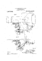
' Figure 1 is a View, partly in side eleva tion and partly in section, of an uncoupling mechanism embodying the invention, the car coupler shown being of the Master Car Builders Dtype. Figure "2 is a view,partly in side elevation well known Specification of Letters latcnt.
App'hcation filed October 6,1921. Seria1'l\T0. 505,69O. i
' to perform an Mammy so, 1922,
and'partly in vertical sectiomof a, portion of the construction illustrated in .F 1," the i H parts being shown in thepositions they as- V s-ume when the coupler lock has been caused extended unlocking fm'ovement.
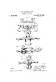
Figure 3 is a detail sectional lview on the line 3+3, Fig.1, portionso'f'the uncoupling i levers and of the coupler-audits carrier iron being'broken away.
Figures is a detail view, partly'in plan and partly in "horizontal section, of a porparts of the uncoution'of the mechanism, 'pllng levers belng broken away.
, F1gure5 a detail view of the. Inechanism partly 1n vertlcalsection'and partly in rearend elevation, a portion of the swinging supporting-meansand portions of the uncoupling levers being broken away.
The car coupler l shownin the clrawings is of'the well known Master Car Builders D-type. alink 3-which-extends downwardly through the couplerhead and is pivotally connected at its'lower end to a u "hichisitself pivotally mounted upon the under side of the head of the coupler} The link 3 and pivoted liftleve'r 4; preferably are Its'lock '2 is movably connectedto' swinging lift lever a constructed in accordance with the standard practice of the botto mlock lift devices of the i D-coupler.
"If a wide range oflateral'swinging movement of the coupler is to be "provideclfor its shank may be formed near-its rear end with a pivot pin openlng 5 adapted to receive'a tail pin (not shown) for pivotally connecting the'coupler to the draft "rigging in a well -known manner.
The swinging lift lever tfisa dapte d'to :2
actuated to cause an unlocking movement of'th'e lock 2 by means 'of averticallyjrd tatable member 6 whichisprefera-bly con? nected interlockingly to said .liftlever by 'a hook and eye connection, the forward end of saidrotatablememberbeing for this purpose provided with a hook Twhich' cooper ateswith'the usual eye 8 'at'therearend of y the pivoted lift lever. Therotatablelnember 6 may be convenientlyformed from a simple bar. It is adapted 'to be operated by'a member 9 swingingly"supported by a linklOto which it is pivotally connected at the center of rotation of the rotatable member 6. This mode of supporting the member 9 permits ed to cooperate with an eye 13 formed in the actuating member 9, and the upper hook 12 being adapted to book through a transversely elongated eye 14; formed on a coupler saddle 15, that is slidably supported on the coupler carrier iron 16 so as to be moved transversely of the car when the coupler 1 swings laterally. Where the coupler is intended to have a very wide range of lateral swing it may be advantageous to provide for the necessary lateral movement of the swinging support 10 by employing the transversely movable coupler saddle 15, as shown, rather than to support the link member 10 directly from the coupler carrier iron.
Rearwardly of the coupler lock2 the vertically rotatable member 6 extends through an aperture 17 formed in the swinging mem-' her 9 by which said rotatable member is caused to perform an unlocking movement. The actuating member 9 and the rotatable member slidably engage each other so that the latter may shift back and forth in response to draft and buffing movements of the coupler. In advanceof the point of pivotal connection of the actuating member 9 and the swinging support 10, which point is the common center of rotation of the members 6 and 9 during the uncoupling operation, the said member 9 is provided with a lug portion 18 extending under and adapted to engage the rotatable member 6, and to the rear of said center of rotation the member 9 is also provided with a portion 19 that extends over and is adapted to engage the opposite side of the rotatable member 0 lVhen the swinging member 9 is actuated. to effect an uncoupling operation its portions 18 and 19 simultaneously engage the member 6 so as to apply thereto oppositely directed forces compelling an unlocking rotation of the'latter.
An unlocking movement of the swinging actuating member 9 is preferably effected from the sides of the car by means of a plurality of independently operating uncoupling levers 20. These levers may be of the well known form'illustrated in-the I. H. Milliken Patent No. 1,184,116, dated May 23 1916, except it is preferred that the bent inner ends 21 of said levers shall extend downsides with angular openings 22 permitting parts.
tarmac swinging actuating member 9 is not required to move to so great an extent in order to permit compensation for the various angular positions which the rotatable member 6 may assume when the coupler swingslaterally.
In assembling the mechanismthe swinging link device 10 is turned laterally until it is at right angles to its normal position when transversely of the car. By this means the its hook 12 may be hooked through the transversely elongated eye 141 of the coupler saddle 15. The member 10 is then dropped to ordinary position, thereby becoming interlocked with the coupler saddleand thus preventing accidental disassociation of these The hook 7 of the rotatable member (3 is then engaged with the eye 8 of the lift lever apivoted to the coupler head. The swinging actuating'member 9 is' associated with the rotatable member 6 and is suspended from the member 10 by threading its eye 13 over the hooked lower end11 of the swinging support. The inner ends 21 of the uncoupling levers 20 are thereafter inserted. in the respective openings of the actuating member 9, their outer endsbeing movably supported in brackets at the sides of the car in the usual manner. As thus assembled the several parts of the mechanism are interlocked so that their accidental disassociation is prevented. p
The rotatable member 6 may be c used-to performan unlocking operation by either of the uncoupling levers 20.- When either of said levers is rotated in the proper direction its bent inner end .21 presses against the swinging actuating member 9 and-causes the latter to rotate, thereby bringing its lug portions 18 and 19 into engagement with opposite sides of the rotatable member 6 and compelling the latter to perform an unlocking movement. During the unlocking rotation of the member 6 and its actuating means 9 the supporting link 10 swings lengthwise of the car as may be required to allow the forward end of the rotatable mem'ber6 readily to conform to the movement of the lift lever 41 through the intermediacy of which the coupler lock 2 is actuated.
We claim r v f 1. In an uncoupling mechanism, the combinat'ion with acar coupler and itslock, of
means for movingsaid lock to unlocked position, said means involving arotatable member operatively connected (to said lock, means for actuating said rotatable member, an uncoupling lever for operating said actuating means and swinging meanspivotally connected to said actuating means at the center of rotation of said rotatable member for supporting said-actuating means.
2. In an uncoupling mechanism, the combination with a car coupler and itslock, of means formoving said lock to unlocked position, said means involving a vertically rotatable member operatively connected to saidlock, swinging means for actuating said rotatable member, an uncoupling lever for actuating said swinging means, and swingmg means supporting sald last named means at the center of rotation ofsaidrotatable member,
3. In, an uncoupling mechanlsm, the
combination with acar coupler and its lock,
4. In an uncoupling mechanism, the com bination with a car coupler and its lock, of means for moving saidlock to'unlocked position, said means involving a rotatable member operatively connected-t0 said lock, swinging means for actuating said rotatable member, an uncoupling lever for causing r0- tation of said swinging means, and swinging means for supporting said first named swing ing means atthe center of rotation of said rotatable member.
5. In an uncoupling mechanism, the combination with a car coupler and its lock, of means for moving said lock to unlocked position, said means involving a rotatable member operatively connected to said lock, an apertured member with which said rotatable member has slidable engagement and through which said rotatable member eX- tends, an uncoupling lever adapted to actuate said apertured member, and swinging means engaging and supporting said apertured member.
6. In an uncoupling mechanism, the combination with a car coupler and its lock, of means for moving said lock to unlocked position, said means involving a member pivotally connected to said coupler, a link operatively interposed between said pivotally connected member and said look, a vertically rotatable member movably engaging said pivotally connected member, an apertured member with which said rotatable member hasdidable engagement and through which said rotatable member extends, an uncoupling lever adapted to actuate said apertured member, and swinging means engaging andv supporting said apertured memb r.
7. In an uncoupling mechanlsm, the comrotatable bination with near coupler and ts lock, of
means for'moving's'aid lock to unlocked-"position, said means involving a rotatableniember operatively connected to said look, a swinging member adapted to actuate said rotatable member, an uncouplinglever adapted to actuate said swinging member, and swinging means for supporting Sa1Cl'SWll1g ing member,'said swinglng means and said swinging member being movably connected at the center of rotation ofsaid rotatable member, and said swinging member a'ndsaid member having slidable engage ment." I 8. In anuncoupling mechanism, the combination with a carcouple'r and'its lock, of means form'ovingsaid lock to'unlocked position, said means involving a rotatable member operatively'connected to'said'lock and extending rearwardly"therefrom, rotatable 111631181 0]? actuating said rotatable member, said rotatable n1eanshaving a floating center of rotation andoperatively engaging opposite sides of said rotatable member,'and an uncoupling lever movably' connected to and adapted to actuate said rotatable means.
bination'with car coupler and its l'o'ck of means for movingsaid' lock'to unlocked position, said means involving a rotatable member operatively connected to said lock and extending rearwardly therefrom, rotatablemeans fo'r'actuating said rotatable member, and an uncoupling lever movably connected to and adapted to actuate said rotatable means, said rotatable member having sliding engagement with said rotatable means, and said rotatable means having a floating center of rotation and being apertured to receive a portion of said rotatable member. i
10. In an uncoupling mechanism, the combination with a car coupler and its lock, of means for moving said lock to unlocked position, saidmeans involving a rotatable member operatively connected to said lock 9. In anuncouplingmechanism,the comand extending rearwardly therefrom, rotatable means for actuating said rotatable member, an imcoupling lever for actuating said rotatable means, and means adapted to swing lengthwise of the car for swingingly supporting said rotatable means, said rotatable means being adapted to actuate said rotatable member by engaging the latter both in advance and to the rear of the cen ter of rotation of said rotatable means, and said uncoupling lever being supported at one end by said rotatablemeans.
11. In anuncoupling mechanism, the com- V bination with a car coupler and its lock, of means for moving sa d lock to unlocked position, said means involvlng a rotatable memberoperatively connected to said lock and extending rearwardly therefrom, an.
apertured member through which saidrotatable member extends, means adapted to swing lengthwise of the car for mo-vably supporting said apertured member, and an uncouplmg lever for actuating said apertured member, said rotatable member having slidable engagement with said apertured member, and said uncoupling lever and said swlngmg means being lnterlockmgly, con nected to sald apertured memben V .12. In an uncoupling mechanism, the comfrom, means movable lengthwise of the car I for supporting said rotatable member rearwardlv of the lock and for actuating said rotatable member, an uncoupling lever adapted to actuate said supportingmeans, and swinging means engaging and mo vably connected to said supporting means and to said carrier iron. v
I 18. In an uncoupling mechanism,the combination with a car coupler, its lock and car rier iron, of means for moving said lock to unlocked position, said means involving a member mounted on said carrier iron and slidable transversely of the car, swinging rams 1s means interlockingly connected to said slidable member, a vertically rotatable member operatively connected to said lock and extending rea rward ly therefrom, means slid- 14. In an uncoupling mechanisimthe combination with car coupler, its lock and carrier 1ron, of means for moving said lock to unlocked position, said means involving a rotatable member operatively connectedto said lock and extending rearwardly' there "from, an apertured member through which said rotatable member extends and withinspect to which it is slidable, anuncoupling lever adapted to actuate said apertured member, and means adapted to swing in a plurality of planes for movably connecting said apertured member to said carrier iron,
and said apertured member affording support forsaid uncouplinglever.
In testimony whereof We afiix our signatures. v t
isAAc n1 MILLIKEN. .WILLIAM J. REGAN.
Priority Applications (1)
| Application Number | Priority Date | Filing Date | Title |
|---|---|---|---|
| US505690A US1417543A (en) | 1921-10-06 | 1921-10-06 | Uncoupling mechanism |
Applications Claiming Priority (1)
| Application Number | Priority Date | Filing Date | Title |
|---|---|---|---|
| US505690A US1417543A (en) | 1921-10-06 | 1921-10-06 | Uncoupling mechanism |
Publications (1)
| Publication Number | Publication Date |
|---|---|
| US1417543A true US1417543A (en) | 1922-05-30 |
Family
ID=24011408
Family Applications (1)
| Application Number | Title | Priority Date | Filing Date |
|---|---|---|---|
| US505690A Expired - Lifetime US1417543A (en) | 1921-10-06 | 1921-10-06 | Uncoupling mechanism |
Country Status (1)
| Country | Link |
|---|---|
| US (1) | US1417543A (en) |
-
1921
- 1921-10-06 US US505690A patent/US1417543A/en not_active Expired - Lifetime
Similar Documents
| Publication | Publication Date | Title |
|---|---|---|
| US1417543A (en) | Uncoupling mechanism | |
| US2162390A (en) | Train coupler | |
| US1479100A (en) | Car coupler | |
| US2396855A (en) | Coupler mechanism | |
| US85147A (en) | t h o m p | |
| US1598353A (en) | Uncoupling mechanism | |
| US1311699A (en) | Planoobaph co | |
| US1944775A (en) | Fifth wheel coupling for tractortrailer combinations | |
| US1919668A (en) | Coupler operating mechanism | |
| US1417547A (en) | Uncoupling mechanism | |
| US1417548A (en) | Uncoupling mechanism | |
| US946176A (en) | Car-coupling. | |
| US1227170A (en) | Car-coupling. | |
| US1184116A (en) | Coupling-release rigging. | |
| US1761449A (en) | Transition car coupling | |
| US2687221A (en) | Automatic mine car coupling | |
| US1712626A (en) | Car coupling | |
| US1417546A (en) | Uncoupling mechanism | |
| US1508379A (en) | Coupler-release rigging | |
| US780235A (en) | Car-coupling. | |
| US1439732A (en) | Coupling-operating mechanism | |
| US734776A (en) | Car-coupling. | |
| US2377257A (en) | Car coupler | |
| US1417544A (en) | Uncoupling mechanism | |
| US307729A (en) | And james w |