US1415744A - Rail anchor - Google Patents
Rail anchor Download PDFInfo
- Publication number
- US1415744A US1415744A US495387A US49538721A US1415744A US 1415744 A US1415744 A US 1415744A US 495387 A US495387 A US 495387A US 49538721 A US49538721 A US 49538721A US 1415744 A US1415744 A US 1415744A
- Authority
- US
- United States
- Prior art keywords
- rail
- anchor
- jaw
- edge
- tie
- Prior art date
- Legal status (The legal status is an assumption and is not a legal conclusion. Google has not performed a legal analysis and makes no representation as to the accuracy of the status listed.)
- Expired - Lifetime
Links
- 239000002184 metal Substances 0.000 description 7
- 241000283986 Lepus Species 0.000 description 2
- ATJFFYVFTNAWJD-UHFFFAOYSA-N Tin Chemical compound [Sn] ATJFFYVFTNAWJD-UHFFFAOYSA-N 0.000 description 2
- 238000010276 construction Methods 0.000 description 2
Images
Classifications
-
- E—FIXED CONSTRUCTIONS
- E01—CONSTRUCTION OF ROADS, RAILWAYS, OR BRIDGES
- E01B—PERMANENT WAY; PERMANENT-WAY TOOLS; MACHINES FOR MAKING RAILWAYS OF ALL KINDS
- E01B13/00—Arrangements preventing shifting of the track
- E01B13/02—Rail anchors
-
- E—FIXED CONSTRUCTIONS
- E01—CONSTRUCTION OF ROADS, RAILWAYS, OR BRIDGES
- E01B—PERMANENT WAY; PERMANENT-WAY TOOLS; MACHINES FOR MAKING RAILWAYS OF ALL KINDS
- E01B2201/00—Fastening or restraining methods
- E01B2201/08—Fastening or restraining methods by plastic or elastic deformation of fastener
Definitions
- My invention relates to rail anchors, and has for its principal object the provision of an improved one-piece rail anchor having jaws for engaging opposite edges of a rail base with spring pressure, and adapted to take a firm shackle hold on the rail during the presence of'creeping pressure on the rail.
- a more specific object of the invention is to provide an improved one-piece anchor constructed so that its jaws are forced apart and the body of the device subjected to a tortional strain when the device is applied to and in its operative position on a rail.
- the invention contemplates an anchor having a normally flat body portion and a jaw portion which is so formed that the anchor. during its application to the rail, is subjected to a twisting strain'and thereby exerts spring pressure against the upper and lower surfaces of the rail base.
- the invention consists in the provision of a new and improved one-piece anchor constructed as hereinafter described and claimed, for carrying out the above stated objects and such other objects as will appear from the following description.
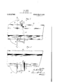
- Fig. 1 is a plan view of the rail anchor.
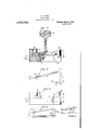
- Fig. 5 is a side View Of the dev ce shown in Fig. i. and
- Fig. 6 is a plan view of a modified form of device.
- 10 designates a railroad rail, and 11 one of the cross-ties on which the rail. is supported.
- the rail anchor consists of a flat piece of metal, cut away as indicated at 12, to provide an upstanding shoulder 13 adapted to bear against one of the vertical edges of the rail base and a notch 14 providing a jaw portion 15 having an angularly disposed lip 16 adapted to fit over the other edge of the rail base.
- the other end of the device is formed with a return bent portion 17 which extends forwardly toward the tie, and terminates in a flat portion adapted to abut against one of the vertical faces of the tie 11.
- the vertical edge of the tie-abutting portion 18 is recessed as indicated at 19, to provide a jaw adapted to fit over the edge of the rail base at a point adjacent the tie.
- the portion 20 of the jaw above the recess 19 is beveled as shown at 21.
- the device is made sothat the effective distance between the jaws 15 and 19, when the device is free of the rail. is less than the distance which the device has to span when being applied to or in operative position on the rail. In other words, in applying the anchor, the jaws 15 and 19 have to be forced away from each other.
- the engagement of the anchor with-the rail base preferably also is such that the body of the anchor is under tortional strain when applied to the rail.
- the notch 14 is formed so that the dimension indicated at B will be less than the thickness of the rail base at the point. engaged by the liplwhen the device 1s in 1ts operative position.
- the lower edge 22 of the lip 16 inclines downwardly' toward the rail base.
- the lip 16 is bent backward y so that the efi'ective distance between the upper edge of the bottom portlon Of the anchor and the edge of the lip 16 is increased by tilting the anchor on a substantially horizontal axis. ⁇ Vhen the device is tilted in the above manner, the vertical edge 23 of the notch 14 may be brought into contact with the vertical edge of the rail base.
- the device will hold the rail against creeping forwardly, that is, in the direction from the anchor toward the tie 11.
- the anchor By forming the anchor so that the jaws 15 and 19 have to be spread apart, and the body portion of the anchor subjected to a tortional strain when the device is in its operative position, the device will take a firm spring grip on the rail, so as to resist the tendency of vibration, or other disturbing influences, from loosening its hold on the rail.
- the anchor will permit the rail to move in the opposite direction without carrying the anchor with it,.and this is desirable because the rearward movement of the anchor is likely to be interfered with by the ballast.
- the tie abutting portion 18 is preferably made relatively short so as to confine its engagement with the tie to a point near the edge of the rail base. ⁇ Vith this construction the anchor may assume different diagonal positions without effecting a substantial change in its point of contactwith the tie.
- Fig. 6 I have shown a modified construction in which the tie abutting portion 18 is curved backwardly from the tie so that the abutment will bear at the same point on the tie regardless of the particular diagonal position assumed by the body portion of the anchor.
- this anchor may be made the same as that shown in Figs. 1 to 5inclusive.
- a one-piece rail anchor recessed at one end and formed with a rearwardly project ing lip to engage the base of the rail at one side thereof, the open end of the recess being narrower than the thickness of the rail base at the place where the lip engages the same when the anchor is in its operative position, a return bent portion at the other end formed with a rail base abutment and terminating in a recessed part to engage the edge of the rail and bear against a tie, the return bent portion being formed above its recess with a. beveled surface, for the purpose described.
- a one-piece rail anchor comprising a spring metal member formed at one end with a jaw for engaging one edge of a rail base, at the other end with a return bent portion adapted to abut against a tie and provide a jaw for engaging the other edge of said rail base, and a web portion between said jaws which is normally fiat when the anchor is free of the rail and is subjected to a tortional strain when the anchor is applied to a rail.
- a one-piece rail anchor comprising a spring metal member formed at one end with a jaw for engaging one edge of a rail base, at the other end with a rail base abutment and with a return bent portion adapted tobear against a tie and provide a jaw for engaging the other edge of said rail base, and a web portion between said first mentioned jaw and said rail base abutment which is normally flat when the anchor is free of the rail and is subjected to a twisting strain when the anchor is applied to a rail.
- a one-piece rail anchor comprising a spring metal member formed at one end with a jaw for engaging one edge of a rail base, at the other end with a return bent portion adapted to bear against a tie, and recessed to provide a jaw for engaging the opposite edge of the rail, and a web portion between said jaws which is normally fiat when the anchor is free of the rail and is twisted when the anchor is applied to a rail; said jaws being arranged so that they are forced apart when the anchor is applied and in its operative position on a rail.
- a one-piece rail anchor comprising a spring metal member formed at one end with a jaw for engaging one edge of a rail base, at the other end with a return bent portion adapted to bear against a tie and recessed at its extremity to provide a jaw for engaging the opposite edge of a rail, and a web portion between said jaws which is normally flat when the anchor is free of the rail and is twisted when the anchor is applied thereto; said 'jaws being arranged so that they are forced apart when the anchor is applied to and in its operative position on a rail and the extremity of said return bent portion being formed above the recess formed therein with a beveled surface, for the purpose described.
- a one-piece rail anchor comprising a spring metal member formed at one end with a jaw having a lip extending obliquely to the body of said member ada ted to engage the upper surface of a rail ase flange at one side of a rail.
- one-niece raii anchor comprising" a. spring nietai. nien'iher formed at one end with a jaw harin iip extending obliquely to the hotly of so; memher adapted to enrorrc the upper surface of a rail base flange r-rt one sirie oi raii, at the other end with rrturn hent portion recessed to provide a ion," tin engaging the raii hase flange a; the other sicio oi? the rail, and. a Web p012 tion intro-rennin between jaws adapted to engage the appriser surface oi?
- a one-piece raii anchor comprising a ing; inetai rnernher formed at one end h a jaw having a hacirwardiy turned lip adapted to er. .go the upper eurtace of a writ base flaiwe at one side of a rail, at the other end Wit 1 a shoulder for engaging the rertieai edge of the rail hase flange at the other sitie of the rail, and with a. return bent norti n adapted to bear against a tie'and hrrrinn; its extremity ret semi to provide a jaw tor e1tgg'a ,ing the mild rail base at a rioint nrthrrent 1.
- a return bent portion adapted to hear againsta tie and having its extremity recessed to provide a jaw for engaging the said rail base at a point adjacent a tie.
- said jaws being arranged so that they ere tort-ed apart when the anchor is appiieri to and in its operative position on a rail.
- a one-piece raii anchor comprising a spring metal member torrneri. at one end with a jaw having a hacirwarriiy turned lip adapted to engage the upper surface of a rail base flan. e at one side of a rail, at the other end with a shonider for engaging the vertical edge oi. the reii hose at the other side of the rail and. with a return bent ortion adapted to hear against a tie and aving its extremity :urecersert to provide a jaw for engaging the saict rail base at a point adjacent said tie, and a Web portion interrening between. said shoulder and said first mentioned jaw which norniaiiy flat when the device is free oi.
- raii anchor cons'it-ing oi? a baritorineti to entenri (tiagonoi across the wit hose provided. at one Q (i t h a jaw for engaging one ecige of Sfitlu hose and the other end with a return hen-t portion terminating in means itor en the other and for hearing against ,nient "with, said tie
Landscapes
- Engineering & Computer Science (AREA)
- Mechanical Engineering (AREA)
- Architecture (AREA)
- Civil Engineering (AREA)
- Structural Engineering (AREA)
- Machines For Laying And Maintaining Railways (AREA)
Description
H. G. WARR.
RAIL ANCHOR.
APPLICATION FILED AUG-25, 1921.
Patented May 9, 1922.
2 SHEETS-SHEET 1- H. 13. WARR. RAIL 'ucnon.
I APPLICATION FILED Aus.25 1921. 1,415,744. Patented May 9; 1922.
2.SHEETS-SHEET 2.
f; a? 4 20 j? 14m 17 UNITEDSTATES PATENT OFFICE.
HAROLD G. WARE, OF PARK RIDGE. ILLINOIS, ASSIGNOR TO THE P-& 1!! COMPANY, OF CHICAGO, ILLINOIS, A CORPORATION OF ILLINOIS.
' RAIL ANCHOR.
Application filed August 25, 1921.
T 0 all "whom itmay concern:
Be it known that I, HAROLD G. WARR, a citizen of the United States, residing at Park Ridge, in the :county of Cook and State of Illinois, have invented certain new and useful Improvements in Rail Anchors, of which the following is a specification.
My invention relates to rail anchors, and has for its principal object the provision of an improved one-piece rail anchor having jaws for engaging opposite edges of a rail base with spring pressure, and adapted to take a firm shackle hold on the rail during the presence of'creeping pressure on the rail.
A more specific object of the invention is to provide an improved one-piece anchor constructed so that its jaws are forced apart and the body of the device subjected to a tortional strain when the device is applied to and in its operative position on a rail. In this connection, the invention contemplates an anchor having a normally flat body portion and a jaw portion which is so formed that the anchor. during its application to the rail, is subjected to a twisting strain'and thereby exerts spring pressure against the upper and lower surfaces of the rail base.
The invention consists in the provision of a new and improved one-piece anchor constructed as hereinafter described and claimed, for carrying out the above stated objects and such other objects as will appear from the following description.
The invention is illustrated in a preferred embodiment in the accompanying drawings, wherein Fig. 1 is a plan view of the rail anchor.
ing its normal configuration when free of the rail.
Fig. 5 is a side View Of the dev ce shown in Fig. i. and
Specification of Letters Patent.
Patented May 9, 1922.
Serial No. 495,387.
Fig. 6 is a plan view of a modified form of device.
Like characters of reference designate like parts in the several figures of the drawmgs.
In the drawings, 10 designates a railroad rail, and 11 one of the cross-ties on which the rail. is supported.
The rail anchor consists of a flat piece of metal, cut away as indicated at 12, to provide an upstanding shoulder 13 adapted to bear against one of the vertical edges of the rail base and a notch 14 providing a jaw portion 15 having an angularly disposed lip 16 adapted to fit over the other edge of the rail base. The other end of the device is formed with a return bent portion 17 which extends forwardly toward the tie, and terminates in a flat portion adapted to abut against one of the vertical faces of the tie 11. The vertical edge of the tie-abutting portion 18 is recessed as indicated at 19, to provide a jaw adapted to fit over the edge of the rail base at a point adjacent the tie. The portion 20 of the jaw above the recess 19 is beveled as shown at 21. to facilitate the application of the device to the rail, as will be hereinafter described. The device is made sothat the effective distance between the jaws 15 and 19, when the device is free of the rail. is less than the distance which the device has to span when being applied to or in operative position on the rail. In other words, in applying the anchor, the jaws 15 and 19 have to be forced away from each other. The engagement of the anchor with-the rail base preferably also is such that the body of the anchor is under tortional strain when applied to the rail. To accomplish this, the notch 14 is formed so that the dimension indicated at B will be less than the thickness of the rail base at the point. engaged by the liplwhen the device 1s in 1ts operative position.
In the drawings. it will be seen thatthe lower edge 22 of the lip 16 inclines downwardly' toward the rail base. In order to compensate for the difference in the vertical dimension B and the thickness of the rail base at the point engaged by the lower ed of the lip 16, the lip 16 is bent backward y so that the efi'ective distance between the upper edge of the bottom portlon Of the anchor and the edge of the lip 16 is increased by tilting the anchor on a substantially horizontal axis. \Vhen the device is tilted in the above manner, the vertical edge 23 of the notch 14 may be brought into contact with the vertical edge of the rail base. Under this condition the jaw 19will be out of line with the opposite edge of the rail base; that is to say, below the same; In order to bring the jaw 19 into operative engagement with the rail base. it is necessary to twist or strain the anchor. During this operation the beveled edge 21 rides over the edge of the rail base until the latter enters the recess 19 of the return bent portion of the anchor.
It will be seen that the device. as described above, will hold the rail against creeping forwardly, that is, in the direction from the anchor toward the tie 11. By forming the anchor so that the jaws 15 and 19 have to be spread apart, and the body portion of the anchor subjected to a tortional strain when the device is in its operative position, the device will take a firm spring grip on the rail, so as to resist the tendency of vibration, or other disturbing influences, from loosening its hold on the rail. The anchor, however, will permit the rail to move in the opposite direction without carrying the anchor with it,.and this is desirable because the rearward movement of the anchor is likely to be interfered with by the ballast. The tie abutting portion 18 is preferably made relatively short so as to confine its engagement with the tie to a point near the edge of the rail base. \Vith this construction the anchor may assume different diagonal positions without effecting a substantial change in its point of contactwith the tie.
In Fig. 6 I have shown a modified construction in which the tie abutting portion 18 is curved backwardly from the tie so that the abutment will bear at the same point on the tie regardless of the particular diagonal position assumed by the body portion of the anchor. In other respects, this anchor may be made the same as that shown in Figs. 1 to 5inclusive.
This application is a continuation in part of my co-pending application Serial No. 449,077, filed March 2, 1921, as a renewal of my application Serial No. 295,555 filed May 8, 1919.
I claim:
1. A one-piece rail anchor recessed at one end and formed with a rearwardly project ing lip to engage the base of the rail at one side thereof, the open end of the recess being narrower than the thickness of the rail base at the place where the lip engages the same when the anchor is in its operative position, a return bent portion at the other end formed with a rail base abutment and terminating in a recessed part to engage the edge of the rail and bear against a tie, the return bent portion being formed above its recess with a. beveled surface, for the purpose described.
2. A one-piece rail anchor comprising a spring metal member formed at one end with a jaw for engaging one edge of a rail base, at the other end with a return bent portion adapted to abut against a tie and provide a jaw for engaging the other edge of said rail base, and a web portion between said jaws which is normally fiat when the anchor is free of the rail and is subjected to a tortional strain when the anchor is applied to a rail.
3. A one-piece rail anchor comprising a spring metal member formed at one end with a jaw for engaging one edge of a rail base, at the other end with a rail base abutment and with a return bent portion adapted tobear against a tie and provide a jaw for engaging the other edge of said rail base, and a web portion between said first mentioned jaw and said rail base abutment which is normally flat when the anchor is free of the rail and is subjected to a twisting strain when the anchor is applied to a rail.
4. A one-piece rail anchor comprising a spring metal member formed at one end with a jaw for engaging one edge of a rail base, at the other end with a return bent portion adapted to bear against a tie, and recessed to provide a jaw for engaging the opposite edge of the rail, and a web portion between said jaws which is normally fiat when the anchor is free of the rail and is twisted when the anchor is applied to a rail; said jaws being arranged so that they are forced apart when the anchor is applied and in its operative position on a rail.
A one-piece rail anchor comprising a spring metal member formed at one end with a jaw for engaging one edge of a rail base, at the other end with a return bent portion adapted to bear against a tie and recessed at its extremity to provide a jaw for engaging the opposite edge of a rail, and a web portion between said jaws which is normally flat when the anchor is free of the rail and is twisted when the anchor is applied thereto; said 'jaws being arranged so that they are forced apart when the anchor is applied to and in its operative position on a rail and the extremity of said return bent portion being formed above the recess formed therein with a beveled surface, for the purpose described.
6. A one-piece rail anchor comprising a spring metal member formed at one end with a jaw having a lip extending obliquely to the body of said member ada ted to engage the upper surface of a rail ase flange at one side of a rail. at the other end with a return hcnt portion recessed to provide a jaw tor engin intji' he rail base flange at the other side oi the raih and a Web portion intro-warring; between said jaws adapted to enrnurro the onrier surface of said rail; sairi ohlirnreir disposed iip being formed so that the rcrticat distance between the i norr tmrer citric thereof and the upper ed 0 ot said not. is tens than the thickness of t 1e :1" it hose iianrro art the point engaged by it tin it. one-niece raii anchor comprising" a. spring nietai. nien'iher formed at one end with a jaw harin iip extending obliquely to the hotly of so; memher adapted to enrorrc the upper surface of a rail base flange r-rt one sirie oi raii, at the other end with rrturn hent portion recessed to provide a ion," tin engaging the raii hase flange a; the other sicio oi? the rail, and. a Web p012 tion intro-rennin between jaws adapted to engage the uniier surface oi? said rail; saint ohtirrueiy disposed lip being formed no that the vertical distance between the inner inner edge thereof and the upper edge ct sairi web is tees than the thickness of the raii. hose flange at the point engaged by said tip and said jaws being arranged. so that they are forced apart when the device is applied to a rnii.
8.. A one-piece raii anchor comprising a ing; inetai rnernher formed at one end h a jaw having a hacirwardiy turned lip adapted to er. .go the upper eurtace of a writ base flaiwe at one side of a rail, at the other end Wit 1 a shoulder for engaging the rertieai edge of the rail hase flange at the other sitie of the rail, and with a. return bent norti n adapted to bear against a tie'and hrrrinn; its extremity ret semi to provide a jaw tor e1tgg'a ,ing the mild rail base at a rioint nrthrrent 1. MW, amt a Web portion 'irrrni hr iii. shonirie'r anti said ritnrt to engage the i. it; said obliquely torment so that the verti- ::e to teen the inner inner edge out said web is less than i rail haee flange at the r tint rail. one! or comprising a oher for o I at one end into or rrit y turned iip rail; said backwarciiy tnrneri tip other end with a shoulder for engaging the vertical edge of a rail base flange, at the other side of the rail. and with. a return bent portion adapted to hear againsta tie and having its extremity recessed to provide a jaw for engaging the said rail base at a point adjacent a tie. amt a web portion in tervening between, seiri shoulder and saint iirst-mentioned jaw adapted to engage the under surface of said NHL, sairi bacirturned lip being formed so that the rerticai die tance between the inner inner edge thereot" and the upper edge o-t seidi Web is iess than i the thickness of the roii hose at the point engaged by said tip, anti. said jaws being arranged so that they ere tort-ed apart when the anchor is appiieri to and in its operative position on a rail.
10. A one-piece raii anchor comprising a spring metal member torrneri. at one end with a jaw having a hacirwarriiy turned lip adapted to engage the upper surface of a rail base flan. e at one side of a rail, at the other end with a shonider for engaging the vertical edge oi. the reii hose at the other side of the rail and. with a return bent ortion adapted to hear against a tie and aving its extremity :urecersert to provide a jaw for engaging the saict rail base at a point adjacent said tie, and a Web portion interrening between. said shoulder and said first mentioned jaw which norniaiiy flat when the device is free oi. the rail and is adapted to bear against the uncier surface of said being formed so that the -'verticai distance between the inner lower edge thereof and the upper edge of said Web is iess than thethicirness of the rail base at the point engaged by said tip anti the jaws being arranged so that the sairi flat web is r-suhjecteri to a twistingstrain when too o vice is an plied to a rait 11. A. one-piece raii anchor cons'it-ing oi? a baritorineti to entenri (tiagonoi across the wit hose provided. at one Q (i t h a jaw for engaging one ecige of Sfitlu hose and the other end with a return hen-t portion terminating in means itor en the other and for hearing against ,nient "with, said tie
Priority Applications (1)
| Application Number | Priority Date | Filing Date | Title |
|---|---|---|---|
| US495387A US1415744A (en) | 1921-08-25 | 1921-08-25 | Rail anchor |
Applications Claiming Priority (1)
| Application Number | Priority Date | Filing Date | Title |
|---|---|---|---|
| US495387A US1415744A (en) | 1921-08-25 | 1921-08-25 | Rail anchor |
Publications (1)
| Publication Number | Publication Date |
|---|---|
| US1415744A true US1415744A (en) | 1922-05-09 |
Family
ID=23968452
Family Applications (1)
| Application Number | Title | Priority Date | Filing Date |
|---|---|---|---|
| US495387A Expired - Lifetime US1415744A (en) | 1921-08-25 | 1921-08-25 | Rail anchor |
Country Status (1)
| Country | Link |
|---|---|
| US (1) | US1415744A (en) |
-
1921
- 1921-08-25 US US495387A patent/US1415744A/en not_active Expired - Lifetime
Similar Documents
| Publication | Publication Date | Title |
|---|---|---|
| US1415744A (en) | Rail anchor | |
| US2171819A (en) | Rail anchor | |
| US1562458A (en) | Metallic railway tie | |
| US2181616A (en) | Rail anchor | |
| US1698975A (en) | Rail anchor | |
| US2078710A (en) | Rail anchor | |
| US2719008A (en) | ruppert | |
| US2632601A (en) | Rail anchor | |
| US1613421A (en) | Rail anchor | |
| US1454366A (en) | Rail anchor | |
| US2446842A (en) | Rail anchor | |
| US1532983A (en) | Tie-plate and rail anchor | |
| US2253704A (en) | Rail anchor | |
| US1646780A (en) | Rail anchor | |
| US1532414A (en) | Rail anchor | |
| US1372852A (en) | Habold g | |
| US1779979A (en) | Rail anchor | |
| US2138447A (en) | Rail anchor | |
| US1020370A (en) | Anticreeper for railroad-rails. | |
| US1350689A (en) | Rail-anchor | |
| US1540614A (en) | Rail anchor | |
| US1551690A (en) | Rail anchor | |
| US977678A (en) | Rail-anticreeper. | |
| US1254634A (en) | Rail-anchor. | |
| US1624028A (en) | Rail anchor |