US1410182A - Trunk-riveting machine - Google Patents
Trunk-riveting machine Download PDFInfo
- Publication number
- US1410182A US1410182A US396109A US39610920A US1410182A US 1410182 A US1410182 A US 1410182A US 396109 A US396109 A US 396109A US 39610920 A US39610920 A US 39610920A US 1410182 A US1410182 A US 1410182A
- Authority
- US
- United States
- Prior art keywords
- shaft
- anvil
- trunk
- carriage
- riveting
- Prior art date
- Legal status (The legal status is an assumption and is not a legal conclusion. Google has not performed a legal analysis and makes no representation as to the accuracy of the status listed.)
- Expired - Lifetime
Links
- 230000007246 mechanism Effects 0.000 description 60
- 230000008093 supporting effect Effects 0.000 description 38
- 230000033001 locomotion Effects 0.000 description 26
- 238000005266 casting Methods 0.000 description 6
- 229910000746 Structural steel Inorganic materials 0.000 description 5
- 230000001276 controlling effect Effects 0.000 description 5
- 235000000396 iron Nutrition 0.000 description 5
- 210000005069 ears Anatomy 0.000 description 4
- 239000011435 rock Substances 0.000 description 4
- 230000003014 reinforcing effect Effects 0.000 description 3
- 238000010276 construction Methods 0.000 description 2
- 239000004744 fabric Substances 0.000 description 2
- 230000002829 reductive effect Effects 0.000 description 2
- ROHFNLRQFUQHCH-UHFFFAOYSA-N Leucine Chemical compound CC(C)CC(N)C(O)=O ROHFNLRQFUQHCH-UHFFFAOYSA-N 0.000 description 1
- 230000032683 aging Effects 0.000 description 1
- 230000005540 biological transmission Effects 0.000 description 1
- 230000008933 bodily movement Effects 0.000 description 1
- 239000000969 carrier Substances 0.000 description 1
- 230000003247 decreasing effect Effects 0.000 description 1
- 230000001419 dependent effect Effects 0.000 description 1
- 230000000994 depressogenic effect Effects 0.000 description 1
- 230000000670 limiting effect Effects 0.000 description 1
- 230000013011 mating Effects 0.000 description 1
- 239000002184 metal Substances 0.000 description 1
- 229910052751 metal Inorganic materials 0.000 description 1
- 108010085990 projectin Proteins 0.000 description 1
- 230000001105 regulatory effect Effects 0.000 description 1
- 230000000284 resting effect Effects 0.000 description 1
- 230000002441 reversible effect Effects 0.000 description 1
- 239000002023 wood Substances 0.000 description 1
Images


Classifications
-
- B—PERFORMING OPERATIONS; TRANSPORTING
- B27—WORKING OR PRESERVING WOOD OR SIMILAR MATERIAL; NAILING OR STAPLING MACHINES IN GENERAL
- B27F—DOVETAILED WORK; TENONS; SLOTTING MACHINES FOR WOOD OR SIMILAR MATERIAL; NAILING OR STAPLING MACHINES
- B27F7/00—Nailing or stapling; Nailed or stapled work
- B27F7/02—Nailing machines
Definitions
- This invention relates to rivet applying mechanism, and particularly to mechanism for riveting a reinforcing strip of metal orv fabric over the joints of the trunk or other container.
- the general object of the present invention is to provide a mechanism of this character whereby rivets may be forced through the reinforcing stripof fabric and into or through the wood or other stock of which the container is made
- a further object is to provide means for supporting a trunk or container with its corner upon a suitableanvil' and feeding the trunk or container step by step over this anvil so as to apply the rivets along the junction between the side Walls and bottom wall of the trunk at evenly spaced distances.
- a further object is to provide means whereby the mechanism may be adjusted so as to adjust or control the spacing between the rivets.
- Still another object is to provide means whereby the machine will not overrun, but
- Still another object is to provide means for supporting the trunk or container upon an anvil and feeding this trunk forward and, as before stated, controlling the feed ofwthe machine so as to space the rivets at uniform dlstances, and in this connection to provide a continuously operating Screw which would ordinarily feed the trunk or container continuously without stopping, but provide means whereby the screw which feeds the carriage supporting the trunk, while contlnuously revolving, -may be carried rear- Ward at the same speed atwhich the trunk carnage is being fed forward so as to thereby hold the trunk in a relatively stationary position with relation to the rivet driving position so that the trunk is stationary while any one pair of rivets is being driven.
- Still another object is to provide simple and positively acting means for manually throwing the operating mechanism into or out of operative engagement with the driv ing gear therefor.
- Figure 4 is an enlarged section on the line 4-4 of. Figure 1;
- Figure 4' is a detail view of the bolt-127 and its casing
- Figure 4 is a fragmentary perspective view of the nut 123 and its handle
- Figure 5 is a section on the line 55 of Figure 1; v Figure 5 is a top plan view ofthe members 110 and 111;
- Figure 5 is. a section on the line a::v of
- Figure 5 of the sleeve 194 los- Figure 10 is a perspective view of the bearing 92 on the rear column;
- Figure 11 is'a perspective view of one of the adjustable trunk engaging hooks and its slide Figure 12 is a perspective view of the trunk supporting frame;
- Figure 13 is a section on the line 13-13 of Figure 21;
- Figure 1.4 is a section on the line 14-44 of Figure 13; 1
- Figure 15 is a perspective view of the clutch operating blade and the link extendin therefrom;
- igure 16 is a view of the clutch operatingz pin lgure 17 is a sectional view of the trunk supporting sleeve, the supporting rod therefor being in elevation;
- Figure 18 is a perspective view of the clutch controlling lever
- Figure 19 is a perspective view of the bracket and cam for automatically throwin off the clutch
- igure 20 is a cross sectional view through one of the rivet feed chutes
- Figure 21 is a fragmentary elevation of the column 10 and the driving mechanism
- Figure 22 is a front elevation of the anvil, the head at the forward end of the machine, the rivet hoppers, and of the rivet driving mechanism;
- Figure 23 is a vertical sectional view through the rivet driving plunger and the anvil
- Figure 24 is a fragmentary vertical sectional view through one side of the head 15 showing one of the rivet driving plungers and the rivet holder and the transfer bar;
- Figure 25 is a fragmentary section on the line 25-25 of Figure 24;
- Figure 26 is a perspective view of one of the rivet carriers
- Figure 27 is a perspective view of one of the rivet carrying heads of the jaws of the rivet carrier:
- Figure 28 is a top plan view of a pair of rivet carrying jaws
- Figure 29 is a fragmentary elevation of the means for limiting the upward move ment of the rivet carrying rod
- Figure 30 is a perspective view of the transfer bar
- Figure 31 is a vertical section on the line 31-31 of Figure 30;
- Figure 32 is a perspective view 'of the transfer bar latch
- our mechanism comprises a supporting column or standard 10 which, as seen in Figure 2, is disposed to one side of the trunk support, and from the lower portion of this standard there extends out laterally the supporting arm 11, which then extends upward, as at 12, and supports on it an anvil, as will be hereafter more fully described.
- bracket 13 Extending laterally from the upper end of the supporting post is a bracket 13 which supports the riveting mechanism immediately over the anvil carried on the. upper end of the arm 11.
- the supporting column 14 At the rear end of the machine and approximately in line with the anvil is the supporting column 14, and carried on the bracket 13 is a riveting head 15, which is illustrated in detail in Figures 22 to 36, and it will be later described in detail. This riveting head is bolted or otherwise attac'hed to the bracket 13.
- This riveting head is illustrated in the drawings as disposed immediately above the anvil carried on the arm 11, and this riveting head supports the rear end of a longitudinally extending rod 17, the forward end of which is supported in a supportingcollar 18 fixed upon the upper end of the column 15 and having the set screw 19 whereby the rod 17 may be held from longitudinal movement.
- Slid-ingly mounted on this rod 17 is a sleeve 20, illustrated in detail in Figure 17, and having :1 depending hanger 21 formed at its lower end with a rearwardly extending spike 22 which is intended to be forced slightly into the forward end of the trunk or other container to a position supporting and centering the trunk.
- This sleeve 20 is adapted to be shifted longitudinally upon the supporting rod 17 by means of the feed mechanism later to be described, but is held from any movement independently of the container or trunk by means of a friction device comprising a block 23 forced against the rod 17 by means of a spring 24.
- this spring block being contained within a cylindrical housing 25 screw-threaded into the sleeve 20, the housing having a bore to receive the block and spring.
- this bore being closed by a screw-threaded plug 26 at its extremity, which bears against the spring so that by turning this plug in one direction or the other, the tension of the spring may be regulated.
- a longitudinally shiftable support or carrier illustrated in Figures 4 and 11 and in side elevation in Figure 1.
- This carrier consists of twoangle irons 27 and 28 which are joined together by a gusset 29 and attached at their upper ends to a downwardly and forwardly extending horn 30 forming part of and depending from a sliding body, designated generally 31, and which is engaged with a longitudinally extending feed screw,
- the angle irons 27 and 28, as illustrated in Figure 4, extend downward and laterally at right angles to each other, and the forwardly projecting flanges 27? and 28 of these angle irons engage over the end of the trunk.
- the angle iron 28 is relatively shorter than the angle iron 27.
- the vertical web of the angle iron 27 is continued downward and inward, as at 32, and then extends laterally inward, as at 33.
- Rearward of the angle irons 27 and 28 is a vertical angle iron 34 which extends vertically downward for a certain distance and then extends laterally and downward, as at 35, and then is angularly bent and extends laterally downward in a reverse direction to a point substantially beneath the vertical portion 34, as at 36, and the extremit of this leg 36, as it.
- a brace 39 which at its upper end is bolted or otherwise attached to the rear end of the body 31, as shown clearly in Figure 1.
- the slide 43 is shown in Figure 11.
- This otherwise detachably engaged therewith is a supporting hook 47 which engages beneath the trunk, as illustrated in Figure 1.
- This hook 47 engages over the end wall of the trunk, with the trunk in the position shown in Figure 2, and the slide 43 is adjustable so as to force the trunk up firmly against the forwardly projecting flanges of the angle irons 27 and 28 and hold the trunk firmly in place over the anvil carried on the projecting arm 11, this arm extending in the body of the trunk (or the opening in the top of the trunk) in the manner illustrated in F igure 2.
- the anvil as illustrated in Figure 23, and as particularly described in our copending application, comprises a plate 48 formed with a central stud 49, and rotatably adjustable upon this stud is the anvil proper 50.
- This anvil in one position has its two sides inclined upward equi-distantly from the axial center of the anvil, and when rotated in the other position, has one of its sides terminating nearer. to the center than the other side. This is fully described in our copending application .and claimed therein and, therefore, need not be described in detail in the present application.
- This anvil is held in its adjusted positions by a ball 51 constituting a locking device.
- a screwthreaded shaft 52 and a parallel power transmitting shaft 53 For the purpose of feeding the carriage and thus feeding the trunk forward over the riveting anvil, we provide a screwthreaded shaft 52 and a parallel power transmitting shaft 53.
- the forward end of the screw-threaded shaft 52 is rotatably mounted in the riveting head 15' in any suitable manner. and the rear end of this shaft is mounted in. a suitable bearing casting 54 carried by the column 14.
- the shaft 53 is likewise mounted at its forward end in the head 15 and at its rear end in a bearing in the column 14. This shaft 53' atits' forward end carries a sprocket wheel 55, as
- That portion of the shaft which supports the hub of the band wheel is reduced in diameter from the main portion of the shaft, as illustrated in Figure 14, and adjacent this reduced ortion of the shaft, the shaft 62 is longitu inally recessed, as at 66, for the reception of a clutch pin 67 (see Figure 16) which is ur ed longitudinally into engagement with the recess 65 in the hub of the band wheel by means of a sprin 68.
- This pin 67 is formed with an angu arly extending lug 69, the inner end face of which is bevelled, as at 70.
- a clutch operating blade 71 (see Figure 15) is pivotally mounted adjacent this clutch pin 67, and when this blade is shifted in one direction, the bevelled end of the blade will engage behind the clutch and force the clutch against the action of the s ring 68 out of the recess and thus unc utch the wheel 64 from the shaft 62.
- the spring 68 will urge the clutch back into engagement.
- This friction comprises a friction disk 72 embraced by a friction ring 73.
- This ring as illustrated in Figure 13, is formed in two sections, each of these sections being provided with an outstanding arm 74 resiliently urged toward each other by a spring 75 carried by a bolt 76 extending through these arms, the tension of the spring being controlled by the wing nut 77. These arms clamp upon a pin 78 which forms the pivot pin for the blade 71.
- This friction device and the clutch mechanism are fully described and illustrated in our copending application.
- the blade 71 is operated by a link 79 connected to a crank arm 80 on a shaft 81 mounted in the. column 10, as illustrated in Figure 21, this shaft 80 extending through suitable bearings on the column and being provided at its extremity with a crank arm 82, in turn connected by a link 83 to a lever 84 which is pivoted at 85 and extends laterally, as illustrated in Figure 3, to the right hand side of the machine and is engaged in a longitudinally extending sup-- porting bar 86.
- Attached to the lever 84 is a downwardly extending arm .87 which has a laterally projectin pin, upon which is mounted a roller 88. his roller is adapted to be operatively engaged by a lifting finger 89 pivotally mounted upon the slide 31, as illustrated in Figure 1, and provided at its for ward end with a forwardly bevelled head 90 resiliently supported in a position to enga e the roller 88 by means of a spring 91. hen this slide 31, therefore, has move forward to its full extent, this head 90 engages beneath the roller 88 and causes a lifting of the lever and the disconnection of the power wheel 64 from the master shaft 62 of the machine.
- This master shaft is 00 geared, as will be later described, with the rivet feeding and driving mechanism and .is operatively connected to the shaft 53 by means of the sprocket chains 56 and 60, as shown in Fi re 3. 1
- the shafts 52 and 53 are mounted in the casting shown in Figure 10, which is at-' tached to the column 14, this casting being designated 54.
- the casting is formed with an upwardly projecting portion 92 having a relatively long bearing 93 for the shaft 53 havin a laterally projecting lug 94 perforated or the passage of a bolt 95.
- This casting is also formed with a relatively long bearing 96 for the worm shaft 52, and the casting is provided with a downwardly extending bracket 97 having a forwardly projecting, perforated lug 98 which is laterally inclined, as illustrated in Figures 5 and 10.
- the shaft 53 passes through the bearing 93 and also passes through a gear wheel supporting arm 99 (see Figure 7) which is extended beyond its central aperture in both directions and has one end perforated for the passage of the screw 95 and its opposite end longitudinally slotted, as at 100, for the passage of a bearing bolt 101 supporting an interm diate gear wheel 102.
- the shaft 53 carries upon it a gear wheel 103 (see Figures 1 and 6) which meshes with the intermediate gear wheel 102, and this interme-' diate gear 102 meshes with a gear wheel 104 mounted upon shaft 52.
- This gear wheel 104 as illustrated in Figure 1, is relatively long so as to provide, for a longitudinal shifting movement of the screw shaft 52.
- This screw shaft 52 is longitudinally reciprocated by a cam 105 (see Figures 1 and 5) mounted upon the driving shaft 53, this cam having a cam groove 106 in its periphery.
- a cam 105 mounted upon the driving shaft 53, this cam having a cam groove 106 in its periphery.
- Mounted upon thescrew shaft is a peripherally grooved Wheel 107.
- Pivotally mounted upon the face of the lug 98 is a block 108 through which passes a pivot bolt 109, and mounted upon the end of this pivot bolt is a bifurcated yoke or holder 110 through which passes a transversely extending carrier bar 111 having downwardly extending lugs 112 adjacent its opposite ends.
- the carrier bar 111 or lever may be shifted transversely.
- This lever 111 carries upon its ends the rollers 114 which engage respectively in the cam groove 106 and in the roove of the wheel 107. By adjusting this lever 111 in one direction or the other, the relative lengths of the arms of the lever may be varied.
- lever 111 toward the right in Figure 5 that portion of the.
- lever to one side of the pivot 109 is increased, and that arm of the lever to the other side of the pivot 109 is decreased so that a relatively slight reciprocation will be given to the screw shaft 52 on each rotation of the. cam 105, and vice versa if the lever 111 be adjusted toward the left in Figure 5, a greater stroke will be given to the shaft 52.
- the purpose of reciprocating the screw shaft 52 is broadly as follows:
- the shaft 52 is constantly rotating and is engaged with a nut carried upon the body 31 of the carriage, but inasmuch as the shaft 52 is reciprocatable and is reciprocated by the cam 105, it follows that if this cam be of the proper form at one period of rotation of the shaft 52, the shaft 52 will be bodily shifted reversely at a speed the same as the speed at which the carriage is moving forward so that the carriage, while moving forward on the screw 52, is held stationary with reference to the riveting mechanism so that the riveting can be performed.
- the roller 114 When the riveting has been performed, the roller 114 has moved into that portion of the cam groove 106 which is disposed entirely at right angles with the plane of rotation so-that there is no bodily movement of the screw 52, and hence the rotation of the screw will carry the carriage forward to a position for a new riveting operation, when once more the roller 114 will engage in the eccentric portion of the cam groove 106 and the shaft 52 will again move 'bodily rearward as the carriage is forced forward with relation to the riveting mechanism.
- the carriage as before stated, carries a nut which engages with the screw-threads of the shaft 52.
- This nut is a half nut and is adapted to be-raised out of engagement with the screw-threaded shaft or de pressed into engagement with it. either automatically or manually.
- the body 31 is recessed, as at 115, the two walls defining this recess being bored, as at 116, to receive the shaft, 53, the body being longitudinally bored at its ends, as at 117, to slide freely on without screwthreaded engagement with the screw-threaded shaft 52, the intermediate portion of the body between these bores 117 being cut away so as to provide a portion 118 having a semi-circular recess on its under face forming a continuation of the bores 117 and resting loosely and sliding on the shaft 52. (See Figure 9).
- the upper face of the body carries a plate 119 which extends downward and forward, as at 120.
- a member 121 Hingedly supported between the arms formed by the recess 115 and swinging on the shaft 53 is a member 121 (see Figure 4 which is formed with an upwardly extending sleeve 122 at one end to loosely surround the shaft 53, as before stated, and at its free end is formed with a semicircular recess 123 having interrupted screw-threads constituting a half nut.
- This plate or body 121 is formed with an outwardly extending handle 124. Extending upward from this handle is a supporting shank 125 carrying a tubular barrel 126 in which is disposed a bolt 127 urged outward by a spring 128, this bolt having laterally projecting pins 129 passing through slots 130 in the barrel.
- a releasingv lever or hand grip 131 Pivoted at the junction of the handle with the bolt 121 is a releasingv lever or hand grip 131, the inner end of which is bifurcated to provide two arms 132 embracing the handle 124 and pivoted thereto by a pivot pin 133, theupper ends of these arms extending upwardly and inwardly to form ears 134, these ears'being arcuately slotted, as at 135, to engage the pin 129 of the bolt 127.
- the rivet feeding mechanism and the rivet setting or overturning mechanism are practically the same as are illustrated in our copending application for patent before referred to, and consists of the head 15, front and rear views of this head being shown in Figures 2 and 3 and the head" being shown in detail in Figures 22 to 36.
- This head is carrie upon the arm 13 to which the head is bolted 1' otherwise attached, and the front a certain distance, then the recess is at larged, as at 141, and extends downward to the bottom of the head.
- a plunger illustrated in Figure 23, J
- this plunger being enlarged at its lower end toform a head, the lower end of this head having a trian llar recess 143 which fits against the angu ar side faces. of the anvil when the plunger is depressed.
- This plunger constitutes a pressing foot and will hereafter be termed a presser foot.-
- the lower end of the head of the presser foot on each side of the recess is cut away, as at 144.
- the head of the presser foot is hollow, and disposed therein is the coil spring 145.
- a shank 146 Operating within the bore of the head is a shank 146 which bears against the spring 145.
- This shank is formed with a head at its lower end and having screw-threaded engagement with the upper end of the presser foot is a screw-threaded bushing'or sleeve 147 having a head whereby it may be rotated and adjusted.
- This bushing limits the upward movement'of the member 142 relative to the member 146.
- a jam nut 148 holds this bushing in its adjusted position.
- the upper end of the shank 146 is screw-threaded, as at 149, and engages in a yoke 150 and is held in adjusted position in this yoke by the jam nuts 151.
- the yoke is bifurcated and perforated to form ears 152.
- These ears are'operatively connected to an arm 153 mounted on a short longitudinal shaft 154, mounted upon the supporting arm 13 and having a depending arm 155 (see Figure 3) connected to a transversely extending, relatively long connecting rod 156 which extends to a crank 157 mounted upon shaft 62.
- the head 15 is formed on each side of the recess 140 with downwardly and inwardly extending recesses or grooves which open at its lower end intov the enlarged portion of the recess 140, and disposed in these grooves are the lower ends of rivet chutes 158 which extend downward from hoppers 159 within which the rivets are placed.
- the rivets are fed from the hoppers by means of feeding mechanism enclosed within the housings 160.
- This feed- I ing mechanism forms no part of our invention and 1s a well known constructlon and.
- the rivets are fed downward through the chutes 158, and the lower ends of the chutes are engaged by reciprocating transfer bars, designated 170, these bars travelling in transverse grooves or tracks formed in the head 15, and each of these bars being formed with a T-shaped, vertically extending slot 171.
- transfer bars 17 O are connected to the lower ends of spring arms 172, which at their upper ends are coiled and engaged with a transverse rock shaft 173 having anoutwardly projecting arm engaged with an upwardly extending link 174 this link being operatively pivoted 'to the plunger so that as the plunger is depresed, the shaft 173 will be rocked in a direction to carry the transfer bars 170 inward where their slots 171 will align with the chutes, and when the plunger moves upward, the transfer bars will be drawn outward.
- the reason for reciprocating the transfer bars by means of the resilient arms 172 is to permit these bars to be locked in an inoperative position by means of the latches 175 (see Fig. 32), these latches being pivoted on the head 15 and being shiftable into or out of engagement with grooves 176 when the transfer bars are drawn outward.
- the transfer bars will be held outward and from reciproe eating movement, the s ring arms 172 yielding as the rock shaft 1 3 is rocked.
- the jaws of this rivet holder are each mounted on an arm 183 which extends laterally from the jaws, then is downwardly deflected, and extends longitudinally and at its end is pivoted to an upwardly -and outwardly extending bar 184.
- the riveting tool will force the rivet out through the small aperture formed by the smaller ends of the jaws and into the work, and as the rivet is forced out and into the work, it will act to spread these jaws apart against the action of the springs 185.
- the jaws 181 are disposed normally within the cut-away portions 144 of the plunger and the distance of this rivet holder formed of the jaws 181 from the work may be controlled by adjusting the set screw 187 which is mounted upon a bracket 188 which bears against the upper end of the bar 184.
- the plungers 179 are reciprocated by longitudinally extending shafts 189, these shafts'having downwardly and laterallyprojecting arms 190 each formed with a ball and socket joint connection to links 191 pivotally connected to the upper endsof the plungers 179.
- Each of these shafts 189 has mounted upon it the upwardly extending arms 192.
- These arms are pivotally connected to pins 193 mounted upon sleeves 194 which are slidingly mounted on connecting rods 195 and 196 respectively. Between the sleeves 194 and the ends of these connecting rods are coiled springs 197 which at the ends of the connecting rods bear against nuts 198.
- These connecting rods 195 and 196 are connected to oppositely projecting arms 199 and 200 which are mounted to rock with a shaft 201, which shaft in turn has a third arm 202 connected by a link 203 to a crank 204 formed on shaft 62.
- the container would not stop atany particular place over the anvil, but would be constantly shifted across the anvil which would, of course, prevent the rivets from being driven. Therefore, it is neces sary,as before stated, to stop the container intermittently, and to this end is provided the cam 105.
- This cam operates, as before described, to oscillate the lever 111 so that at the instant when the rivet is to be driven, this cam 105 acts to shift the screw 52 rearward to exactly the same extent that the carriage 30 is being driven forward so that the carriage and container 'are held stationary relative to the anvil at this time.
- the feed spacing that is rivet spacing
- the gears 102, 103 and 104 shown in Figures 1 and 6.
- the feed worm or feed screw 52 makes one revolution to one revolution of the shaft 53 for a rivet spacing.
- the pitch of the feed worm under these circumstances is 19;".
- the cam gives "a reciprocation of to the feed worm, and
- the cam groove 106 has the same pitch as the feed worm or screw, thus causing the feed worm or screw 52 to be drawn backward at the same speed as it is being driven forward by the gearing at the time that the rivets are being driven.
- the screw 52 will make 4 turn to one revolution of the main shaft. Therefore, the carriage 30 is advanced 1 3' during a quarter turn of the worm, and the cam rocker 111 operated by the earn 105 advances the worm 1 g
- the screw 52 is drawn backward b the cam 105 a" and the feed nut is being a vanced leaving a space between the nut and carriage on the forward end of 1 g.
- the nut 121 is advanced The cam advances the feed screw and the carriage bodily g". The two operations occur at the same time.
- the riveting proceeds until the'container carried upon the carriage 30 and by sleeve 20 has arrived at such a position that its rear end is in a predetermined spaced relation from the anvil and the last pair of rivets have been driven.
- the head 90 on the carriage engages beneath the roller 88 on the controlling lever 84 and raises the controlling lever, causing the clutch shifting blade 71 to oscillate past and against the bevelled face of the clutch pin 67, withdrawing the clutch pin and unclutching the shaft 62 from the driving wheel 64.
- the friction members 7 2 and 73 as soon as the power is unclutched from' the shaft 62, cause the immediate" stoppage of the shaft 62 so that it does not overrun.
- the trunk ma be larger containers, as
- a riveting machine of the character described including a supporting column, a supporting arm extending laterally from the supporting column and then extending upward, an anvil carried upon said supporting arm, riveting mechanism mounted upon the column and disposed above the supporting arm and anvil, a carriage mounted in line with the anvil for movement in a plane at right angles to the supporting arm, said carriage being vertically disposed and having trunk engaging clamps projecting from one face whereby to engage the end of a trunk, and power operated mechanism for giving a step by step movement to said carriage toward the anvil and for operating the riveting mechanism during the period when the carriage is at rest.
- A-riveting mechanism of the character described including an anvil, riveting mechanism disposed above the anvil, a carriage mounted for longitudinalmovement toward and from the anvil, means for giving an intermittent step by step movement of the carriage toward the anvil and for operating said riveting mechanism-when the carriage is at rest, said carriage comprising downwardly and outwardly angularly disposed and hook-shaped members slidingly mounted on and carried by said bars for engaging an inverted container therewith and means for manually shifting said members to grip a container therebyr
- a riveting mechanism of the character described including an anvil, riveting mechanism disposed above the anvil, a carriage mounted for.
- said carriage comprising downwardly and outwardly angularly disposed container engaging bars, members carried by said bars for engaging an inverted container therewith, a downwardly and inwardly extending bar supported by one of said angularly disposed bars, and an adjustable member slidably mounted on the last named bar and having a hook adapted to en age a container.
- riveting mechanism of the character described including an anvil, riveting mechanism disposed above the anvil, a carriage mounted for longitudinal movement toward and from the anvil, means for giving an intermittent step by step movement of the carriage toward the anvil and for operating said riveting mechanism when the carriage is at rest, said carriage comprising downwardly and outwardly angularly disposed container engaging bars, members carried by said bars for engaging an inverted container therewith, a downwardly and inwardly extending bar supported by one of said angularly disposed bars, an adjustable member slidably mounted on the last named bar and having a hook adapted to engage a container, two members slidingly mounted upon said bar in spaced relation to each other, and means for longitudinally adjusting said members, each of said members be ing provided with a hook adapted to engage the container.
- a riveting machine including an anvil, riveting mechanism disposed above the anvil, a carriage movable toward and from the riveting mechanism, means for giving a step by step movement to the carriage toward the anvil and operating the rivet-ing mechanism when the carriage is at rest, said carriage comprising downwardly and outwardly divergent-1y related trunk supporting bars, a downwardly and inwardly extending bar carried at the end of one of said trunk supporting bars, a slide mounted upon said bar and having a hook adapted to engage a trunk, and a screw-threaded adjusting rod mounted on the carriage and operatively engaging said slide whereby it may be adjusted.
- a riveting machine of the character described comprising an anvil, riveting mechanism disposed above the anvil, a carriage prising downwardly divergent trunk engag--v mg bars, a vertical support centrally, disposed with relation to said bars, a downwardly and inwardly extending bar en aging said support, trunk engaging mem rs mounted upon said downwardly and inwardly extending bar and having hooks adapted to engage a trunk, and a rail supporting the lower end of said centrally disposed member.
- a trunk riveting machine including an anvil having angularly related faces, a supporting arm for the anvil extending laterally and upward, riveting mechanisms disposed above the faces of the anvil and coactmg therewith, a vertically disposed carriage adapted to'supportone end of a trunk and movable toward or from the anvil, said carriage moving in.
- a trunk rivetin machine including an anvil, a riveting mec anism disposed above the anvil and coacting therewith, a carriage adapted to support one end of a trunk and movable toward or from the anvil, means for moving the carriage toward the anvil including a power operated screw-threaded member, and a screw-threaded member mounted on the carriage and engaging the first named screw-threaded member, said carriage supported screw-threaded member being manually movable intoor out of engagement with the power operated screwthreaded member.
- a trunk riveting machine including an anvil, sliding means for supporting one end of the trunk with its corner over the anvil, a carriage for supporting the opposite end of the trunk, and power operated mechanism for shifting said carriage step by step over the face of the anvil.
- a trunk riveting machine including a supporting column, an anvil, a riveting mechanism supported by the column and disposed above the anvil, a bar extending forward from the riveting mechanism, a sleeve sliding on said bar and having a depending hanger formed with means where- 'by it may engage one end of a. trunk, a
- a riveting mechanism including a supporting column, an anvil carried theresupporting column, an anvil carried thereby and adapted to sup-port a trunk, a carriage engageable with one end of the trunkand movable toward or from the anvil, means for shifting said carriage toward the anvil including a power operated screw-threaded shaft, a screw-threaded member movably mounted upon the carriage and normally engageable with said shaft, means for automatically shifting the screw-threaded memher on the carriage out of engagement with the shaft when thecarriage arrives in predetermined proximity to the anvil, said means including a spring urging the screwthreaded member away from the shaft, a latch holding the screw-threaded member in engagement with the shaft, and a member engageable with the latch to release it when the carriage has arrived in predetermined proximity to the anvil.
- a riveting machine including an anvil, a container carriage movable toward or from the anvil, riveting mechanism disposed above the anvil, and means for giving an intermittent step by step forward movement to the carriage toward the anvil comprising a screw-threaded, constantly rotating shaft with which the carriage has threaded engagement, and means for reciprocating said shaft.
- a riveting machine including an anvil, a container carriage movable toward or from the anvil, riveting mechanism disposed above the anvil, means for giving an intermittent step by step forward movement to the carriage toward the anvil comprising a screw-threaded, constantly rotating shaft with which the carriage has threaded engagement.
- means for reciprocating said shaft including a pivoted lever operatively engaging the shaft at one end, and a power operated cam movably engaging the lever at the other end.
- a riveting machine including an anvil. a container carriage movable toward or engaging the shaft at one end, a power operated cam movably engaging the lever at the other end, and means for longitudii'lally shifting the lever relative to the center of motion to thereby control the relative length of the shaft engaging and the cam engaging arms of the lever.
- a riveting machine including an anvil, a container carriage movable toward or from the anvil, riveting mechanism disposed above the anvil, means for giving an intermittent step by step forward movement to the carriage toward the anvil comprising a screw-tlu'eaded, constantly rotating shaft with which the carriage has threaded engagement, means for reciprocating said shaft including a pivoted lever operatively engaging the shaft atone end, a power operated cam movably engaging the lever at the other end, means for longitudinally shifting the lever relative to the center of motion to thereby control the relative length of the shaft engaging and the cam engaging arms of the lever, said means comprising a bifurcated pivoted member within which the lever is disposed, and adjusting screws carried by the lever on each side of said member and engaging the member.
- a machine for riveting the bottoms to the side walls of trunks col-uprising a supporting column having a lateral, upwardly turned bracket, an anvil mounted upon the bracket and having oppositely bevelled, downwardly and outwardly extending faces, a bracket extending from the upper portion of the column, a head mounted upon said bracket, oppositely disposed riveting mechanisms mounted upon said head and including means for feeding rivets, means for forcing the rivets into and through the work and against said anvil, a longitudinally extending guide bar mounted upon the head and extending therefrom in one direction, a sleeve slidingly mounted upon said guide bar and having a depending member formed with a trunk engaging pin, a carriage disposed on the other side of the anvil from said sleeve and mounted for movement toward or from the anvil and having means for engaging and supporting the opposite end of the trunk, power operated means for intermittently shifting the carriage forward and permitting it to rest, means for adjusting the extent to which the carriage moves between each rest, power operated means for operating said shaft, and power operated means for
- A'trunk riveting mechanism including a supporting column having a laterally extending and then upwardly extending bracket, an anvil mounted thereon and having oppositely bevelled faces, a head supported above the anvil and supported by said column and having a vertically reciprocatable presser foot movable toward or from the anvil, oppositely disposed rivet driving mechanisms carried by the head, means for feeding rivets to said rivet driving mechanisms, a guide bar extending forwardly from the head, a sleeve slidingly mounted thereonand having means for engaging one end of a trunk, a carriage mounted on the opposite side of the anvil relative to the sleeve and having means thereon for engaging the trunk, a lon itudinally extending screwthreaded shaft with which the carriage has operative engagement, the shaft being longitudinally reciprocatable, power operated means for rotating said shaft and intermittently longitudinally reciprocating it to thereby intermittently hold thecarriage stationary relative to the anvil, driving mechanism including a driven shaft, a power operated driving member, ,a
Landscapes
- Engineering & Computer Science (AREA)
- Mechanical Engineering (AREA)
- Life Sciences & Earth Sciences (AREA)
- Forests & Forestry (AREA)
- Press Drives And Press Lines (AREA)
Description
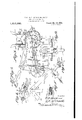
T. M. HOUSE AND H. R. MCCONNELL.
TRUNK RIVETING MACHINE.
APPLICATION FILED JULYH. 1920.
Patented Mar. 21, 1922 6SHEETSSE:IEET l- T. M. HOUSE AND H. R. McCONNELL TRUNK R IVETING MACHINE.
APPLICATION FILED JULYJ4.1920.
1,410,182, P1161161 Mar. 21, 1922 6 SHEETSSHEET 2.
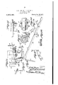
T. M. HOUSE AND H. R. McCONNELL.
TRUNK RIVETING MACHINE.
APPLICATION FILED JULY14',1920.
Patented Mar. 21, 1922,
6 SHEETS-SHEET 3- 5] vwe M1014 T. M. HOUSE AND H. R. IVIcCONNELL.
TRUNK RIVETING MACHINE.
APPLICATION FILED JULY14, 1920.
Patented Mar. 21, 1922.
6 SHEETS-SHEET 4'.
5] mmmh w T. M. HOUSE AND H. R. McCONNELL.
TRUNK RIVETING MACHINE.
APPLICATION FILED JULY 14. 1920.
Patented Mar. 21, 1922.
6 SHEETS-SHEET 5.
T. M. HOUSE AND H. R. McCONNELL. I TRUNK mvnmc MACHINE.
APPLICATION HLEU JULY 1.4, 1920.
1,410, 182. I Patented Mar. 21, 1922.
6 $HEETS$HEET 6. Q
wwlmz llllllllfl UNITED STATES PATENT OFFICE.
THOMAS M. HOUSE AND HARRY R, MGGONNELL, OF RICHMOND, VIRGINIA, ASSIGNORS TO SEWARD TRUNK AND BAG COMPANY, OF PETERSBURG, VIRGINIA, A GORPORA- TION OF VIRGINIA.
TRUNK-RIVETING MACHINE.
To all whom it may concern:
Be it knownthat-we, THOMAS M. House and HARRY R. MoCoNNELL, citizens of the United States, residing at Richmond, in the county of'Henrico and State of Virginia, have invented certain new and useful Improvements in T runk-Riveting Machines, of which the following is a specification, reference being had to the accompanying drawings.
This invention relates to rivet applying mechanism, and particularly to mechanism for riveting a reinforcing strip of metal orv fabric over the joints of the trunk or other container. V
In a copending application Serial Nof 396,110 of even date herewith, we have illustrated and described a mechanism for riveting this reinforcing strip over the joint between the side and end walls of the trunk or like container, but the mechanism described in this copending application is not adapted for applying the strip and riveting it at the junction of the bottom, side and end Walls of the container.
The general object of the present invention is to provide a mechanism of this character whereby rivets may be forced through the reinforcing stripof fabric and into or through the wood or other stock of which the container is made A further object is to provide means for supporting a trunk or container with its corner upon a suitableanvil' and feeding the trunk or container step by step over this anvil so as to apply the rivets along the junction between the side Walls and bottom wall of the trunk at evenly spaced distances. I
A further object is to provide means whereby the mechanism may be adjusted so as to adjust or control the spacing between the rivets. 1
Still another object is to provide means whereby the trunk may be firmly clamped in place-upon the machine and whereby containers of different sizes may be riveted upon the same machine by1'a suitable adjustment. Another object is to provide means for automatically releasing the feeding mechanism when the final rivet of a line of rivets has been applied.
Still another object is to provide means whereby the machine will not overrun, but
-' and its connected parts;
Specification of Letters Patent. Patented M 21 1922 1920. Serial No. 396,109.
that as soon as the power is cut off, the mech anism will stop.
Still another object is to provide means for supporting the trunk or container upon an anvil and feeding this trunk forward and, as before stated, controlling the feed ofwthe machine so as to space the rivets at uniform dlstances, and in this connection to provide a continuously operating Screw which would ordinarily feed the trunk or container continuously without stopping, but provide means whereby the screw which feeds the carriage supporting the trunk, while contlnuously revolving, -may be carried rear- Ward at the same speed atwhich the trunk carnage is being fed forward so as to thereby hold the trunk in a relatively stationary position with relation to the rivet driving position so that the trunk is stationary while any one pair of rivets is being driven.
Still another object is to provide simple and positively acting means for manually throwing the operating mechanism into or out of operative engagement with the driv ing gear therefor.
Other objects will appear hereafter and have to do with the details of construction and arrangement of parts as will more fully appear later.
' Our invention is illustrated in the accompanying drawings, wherein Figure 3 is a section on the line 3-3 of Figure 1;
Figure 4 is an enlarged section on the line 4-4 of. Figure 1;
Figure 4' is a detail view of the bolt-127 and its casing; I
Figure 4 is a fragmentary perspective view of the nut 123 and its handle;
Figure 5 is a section on the line 55 of Figure 1; v Figure 5 is a top plan view ofthe members 110 and 111;
Figure 5 is. a section on the line a::v of
Figure 5 of the sleeve 194 los- Figure 10 is a perspective view of the bearing 92 on the rear column;
Figure 11 is'a perspective view of one of the adjustable trunk engaging hooks and its slide Figure 12 is a perspective view of the trunk supporting frame;
Figure 13 is a section on the line 13-13 of Figure 21;
Figure 1.4 is a section on the line 14-44 of Figure 13; 1
Figure 15 is a perspective view of the clutch operating blade and the link extendin therefrom;
igure 16 is a view of the clutch operatingz pin lgure 17 is a sectional view of the trunk supporting sleeve, the supporting rod therefor being in elevation;
Figure 18 is a perspective view of the clutch controlling lever;
Figure 19is a perspective view of the bracket and cam for automatically throwin off the clutch;
Figure 21 is a fragmentary elevation of the column 10 and the driving mechanism;
Figure 22 is a front elevation of the anvil, the head at the forward end of the machine, the rivet hoppers, and of the rivet driving mechanism;
Figure 23 is a vertical sectional view through the rivet driving plunger and the anvil;
Figure 24 is a fragmentary vertical sectional view through one side of the head 15 showing one of the rivet driving plungers and the rivet holder and the transfer bar;
Figure 25 is a fragmentary section on the line 25-25 of Figure 24;
Figure 26 is a perspective view of one of the rivet carriers;
Figure 27 is a perspective view of one of the rivet carrying heads of the jaws of the rivet carrier:
Figure 28 is a top plan view of a pair of rivet carrying jaws;
Figure 29 is a fragmentary elevation of the means for limiting the upward move ment of the rivet carrying rod;
Figure 30 is a perspective view of the transfer bar;
Figure 31 is a vertical section on the line 31-31 of Figure 30;
Figure 32 is a perspective view 'of the transfer bar latch;
Referring to Figures 1, 2, and 3, wherein the general construction of the machine is illustrated, it will be seen that our mechanism comprises a supporting column or standard 10 which, as seen in Figure 2, is disposed to one side of the trunk support, and from the lower portion of this standard there extends out laterally the supporting arm 11, which then extends upward, as at 12, and supports on it an anvil, as will be hereafter more fully described.
Extending laterally from the upper end of the supporting post is a bracket 13 which supports the riveting mechanism immediately over the anvil carried on the. upper end of the arm 11. At the rear end of the machine and approximately in line with the anvil is the supporting column 14, and carried on the bracket 13 is a riveting head 15, which is illustrated in detail in Figures 22 to 36, and it will be later described in detail. This riveting head is bolted or otherwise attac'hed to the bracket 13. This riveting head is illustrated in the drawings as disposed immediately above the anvil carried on the arm 11, and this riveting head supports the rear end of a longitudinally extending rod 17, the forward end of which is supported in a supportingcollar 18 fixed upon the upper end of the column 15 and having the set screw 19 whereby the rod 17 may be held from longitudinal movement. Slid-ingly mounted on this rod 17 is a sleeve 20, illustrated in detail in Figure 17, and having :1 depending hanger 21 formed at its lower end with a rearwardly extending spike 22 which is intended to be forced slightly into the forward end of the trunk or other container to a position supporting and centering the trunk. This sleeve 20 is adapted to be shifted longitudinally upon the supporting rod 17 by means of the feed mechanism later to be described, but is held from any movement independently of the container or trunk by means of a friction device comprising a block 23 forced against the rod 17 by means of a spring 24. this spring block being contained within a cylindrical housing 25 screw-threaded into the sleeve 20, the housing having a bore to receive the block and spring. this bore being closed by a screw-threaded plug 26 at its extremity, which bears against the spring so that by turning this plug in one direction or the other, the tension of the spring may be regulated.
The rear end of the trunk is supported on a longitudinally shiftable support or carrier, illustrated in Figures 4 and 11 and in side elevation in Figure 1. This carrier consists of twoangle irons 27 and 28 which are joined together by a gusset 29 and attached at their upper ends to a downwardly and forwardly extending horn 30 forming part of and depending from a sliding body, designated generally 31, and which is engaged with a longitudinally extending feed screw,
' as will be later described. The angle irons 27 and 28, as illustrated in Figure 4, extend downward and laterally at right angles to each other, and the forwardly projecting flanges 27? and 28 of these angle irons engage over the end of the trunk. The angle iron 28 is relatively shorter than the angle iron 27. The vertical web of the angle iron 27 is continued downward and inward, as at 32, and then extends laterally inward, as at 33. Rearward of the angle irons 27 and 28 is a vertical angle iron 34 which extends vertically downward for a certain distance and then extends laterally and downward, as at 35, and then is angularly bent and extends laterally downward in a reverse direction to a point substantially beneath the vertical portion 34, as at 36, and the extremit of this leg 36, as it. may be called, is provi ed with a roller 37 engaging with a longitudinally extending rod 38 constituting a track, and mounted u on the bases" of the columns 14 and 15. xtendingupward and rearward from the'lower portion of the vertical part" 34 is a brace 39, which at its upper end is bolted or otherwise attached to the rear end of the body 31, as shown clearly in Figure 1. Mounted upon a bracket 40 extending rearward from the lateral extremity of the angle iron 27, is an adjusting screw 41 which is held from longitudinal movement and which is provided at its upper end with a crank handle 42 whereby it may be rotated, and sliding u on the bar 32 are two slides 43 and 43. ne of these slides is designed for use with relatively shallow container sections, like the tops of trunks, and the other is to be used with a body of a trunk. Both of these slides are of the same character, and one of these slides, as for instance,
the slide 43 is shown in Figure 11. This otherwise detachably engaged therewith is a supporting hook 47 which engages beneath the trunk, as illustrated in Figure 1. This hook 47 engages over the end wall of the trunk, with the trunk in the position shown in Figure 2, and the slide 43 is adjustable so as to force the trunk up firmly against the forwardly projecting flanges of the angle irons 27 and 28 and hold the trunk firmly in place over the anvil carried on the projecting arm 11, this arm extending in the body of the trunk (or the opening in the top of the trunk) in the manner illustrated in F igure 2. The anvil, as illustrated in Figure 23, and as particularly described in our copending application, comprises a plate 48 formed with a central stud 49, and rotatably adjustable upon this stud is the anvil proper 50. This anvil in one position has its two sides inclined upward equi-distantly from the axial center of the anvil, and when rotated in the other position, has one of its sides terminating nearer. to the center than the other side. This is fully described in our copending application .and claimed therein and, therefore, need not be described in detail in the present application. This anvil is held in its adjusted positions by a ball 51 constituting a locking device.
It is to be understood that the carriage formed of the members27, 28 and of the bar 34, is to be shifted step by step forward, and
that this, through the trunk itself, will shift the sleeve 20 forward on the guide bar 17 and that thus the trunk will be shifted step by step forward over the anvil. The mechanism which we will now describe is designed to shift the trunk forward one step and then the trunk remains stationary while the rivets For the purpose of feeding the carriage and thus feeding the trunk forward over the riveting anvil, we provide a screwthreaded shaft 52 and a parallel power transmitting shaft 53. The forward end of the screw-threaded shaft 52 is rotatably mounted in the riveting head 15' in any suitable manner. and the rear end of this shaft is mounted in. a suitable bearing casting 54 carried by the column 14. The shaft 53 is likewise mounted at its forward end in the head 15 and at its rear end in a bearing in the column 14. This shaft 53' atits' forward end carries a sprocket wheel 55, as
illustrated in Figure 3, over which passes! a sprocket chain 56, which in turn passes over a sprocket wheel 57 mounted upon a shaft 58 and carrying a sprocket wheel 59 over which passes a sprocket chain 60, which in turn passes over a sprocket wheel 61 mounted upon a shaft 62 mounted in suitable bearing brackets 63 extending from the laterally disposed column 10, as shown in Figures 2, 3, and 12. This shaft 62 carries upon it at one end a band wheel 64 whereby power is transmitted to the shaft 62 from any suitable source. This band wheel, as illustrated in Figure 14, is loose on the shaft 62, but the hub of the band wheel is provided with a recess 65 adjacent one end face of the hub. That portion of the shaft which supports the hub of the band wheel is reduced in diameter from the main portion of the shaft, as illustrated in Figure 14, and adjacent this reduced ortion of the shaft, the shaft 62 is longitu inally recessed, as at 66, for the reception of a clutch pin 67 (see Figure 16) which is ur ed longitudinally into engagement with the recess 65 in the hub of the band wheel by means of a sprin 68. This pin 67 is formed with an angu arly extending lug 69, the inner end face of which is bevelled, as at 70. A clutch operating blade 71 (see Figure 15) is pivotally mounted adjacent this clutch pin 67, and when this blade is shifted in one direction, the bevelled end of the blade will engage behind the clutch and force the clutch against the action of the s ring 68 out of the recess and thus unc utch the wheel 64 from the shaft 62. When, however, the blade is shifted out of engagement with the bevelled end face 70 of the clutch pin, the spring 68 will urge the clutch back into engagement. Thus, as soon as the plate 71 is operated in one direction by a controlling lever, as will be later stated, power is disconnected from the shaft 62, and as soon as the blade is shifted in the other direction, the shaft 62 is connected to the source of power. For the purpose of preventing the shaft from overrunning after it is disconnected from the source of power, constant friction is applied to the shaft 62. This friction comprises a friction disk 72 embraced by a friction ring 73. This ring, as illustrated in Figure 13, is formed in two sections, each of these sections being provided with an outstanding arm 74 resiliently urged toward each other by a spring 75 carried by a bolt 76 extending through these arms, the tension of the spring being controlled by the wing nut 77. These arms clamp upon a pin 78 which forms the pivot pin for the blade 71. This friction device and the clutch mechanism are fully described and illustrated in our copending application.
The blade 71 is operated by a link 79 connected to a crank arm 80 on a shaft 81 mounted in the. column 10, as illustrated in Figure 21, this shaft 80 extending through suitable bearings on the column and being provided at its extremity with a crank arm 82, in turn connected by a link 83 to a lever 84 which is pivoted at 85 and extends laterally, as illustrated in Figure 3, to the right hand side of the machine and is engaged in a longitudinally extending sup-- porting bar 86. When the handle end of this lever is raised upward, the blade 71 is forced into engagement with the clutch pin 67 to retract the clutch pin from its engagement with the driving wheel 64, and when the handle end of the lever is forced downward, the blade 71 releases its engagement with the clutch pin andthe clutch again engages the shaft 62 with the driving wheel 64.
Attached to the lever 84 is a downwardly extending arm .87 which has a laterally projectin pin, upon which is mounted a roller 88. his roller is adapted to be operatively engaged by a lifting finger 89 pivotally mounted upon the slide 31, as illustrated in Figure 1, and provided at its for ward end with a forwardly bevelled head 90 resiliently supported in a position to enga e the roller 88 by means of a spring 91. hen this slide 31, therefore, has move forward to its full extent, this head 90 engages beneath the roller 88 and causes a lifting of the lever and the disconnection of the power wheel 64 from the master shaft 62 of the machine. This master shaft is 00 geared, as will be later described, with the rivet feeding and driving mechanism and .is operatively connected to the shaft 53 by means of the sprocket chains 56 and 60, as shown in Fi re 3. 1
The shafts 52 and 53 are mounted in the casting shown in Figure 10, which is at-' tached to the column 14, this casting being designated 54. The casting is formed with an upwardly projecting portion 92 having a relatively long bearing 93 for the shaft 53 havin a laterally projecting lug 94 perforated or the passage of a bolt 95. This casting is also formed with a relatively long bearing 96 for the worm shaft 52, and the casting is provided with a downwardly extending bracket 97 having a forwardly projecting, perforated lug 98 which is laterally inclined, as illustrated in Figures 5 and 10. The shaft 53, as before stated, passes through the bearing 93 and also passes through a gear wheel supporting arm 99 (see Figure 7) which is extended beyond its central aperture in both directions and has one end perforated for the passage of the screw 95 and its opposite end longitudinally slotted, as at 100, for the passage of a bearing bolt 101 supporting an interm diate gear wheel 102. The shaft 53 carries upon it a gear wheel 103 (see Figures 1 and 6) which meshes with the intermediate gear wheel 102, and this interme-' diate gear 102 meshes with a gear wheel 104 mounted upon shaft 52. This gear wheel 104, as illustrated in Figure 1, is relatively long so as to provide, for a longitudinal shifting movement of the screw shaft 52. This screw shaft 52 is longitudinally reciprocated by a cam 105 (see Figures 1 and 5) mounted upon the driving shaft 53, this cam having a cam groove 106 in its periphery. Mounted upon thescrew shaft is a peripherally grooved Wheel 107. Pivotally mounted upon the face of the lug 98 is a block 108 through which passes a pivot bolt 109, and mounted upon the end of this pivot bolt is a bifurcated yoke or holder 110 through which passes a transversely extending carrier bar 111 having downwardly extending lugs 112 adjacent its opposite ends. Through these lugs pass adjusting screws 113 which engage the end faces of the yoke 110, and by adjusting these screws, one in one direction and the other in the other direction, the carrier bar 111 or lever may be shifted transversely. This lever 111 carries upon its ends the rollers 114 which engage respectively in the cam groove 106 and in the roove of the wheel 107. By adjusting this lever 111 in one direction or the other, the relative lengths of the arms of the lever may be varied.
-Thus, by adjusting this. lever 111 toward the right in Figure 5, that portion of the.
lever to one side of the pivot 109 is increased, and that arm of the lever to the other side of the pivot 109 is decreased so that a relatively slight reciprocation will be given to the screw shaft 52 on each rotation of the. cam 105, and vice versa if the lever 111 be adjusted toward the left in Figure 5, a greater stroke will be given to the shaft 52.
The purpose of reciprocating the screw shaft 52 is broadly as follows: The shaft 52 is constantly rotating and is engaged with a nut carried upon the body 31 of the carriage, but inasmuch as the shaft 52 is reciprocatable and is reciprocated by the cam 105, it follows that if this cam be of the proper form at one period of rotation of the shaft 52, the shaft 52 will be bodily shifted reversely at a speed the same as the speed at which the carriage is moving forward so that the carriage, while moving forward on the screw 52, is held stationary with reference to the riveting mechanism so that the riveting can be performed. When the riveting has been performed, the roller 114 has moved into that portion of the cam groove 106 which is disposed entirely at right angles with the plane of rotation so-that there is no bodily movement of the screw 52, and hence the rotation of the screw will carry the carriage forward to a position for a new riveting operation, when once more the roller 114 will engage in the eccentric portion of the cam groove 106 and the shaft 52 will again move 'bodily rearward as the carriage is forced forward with relation to the riveting mechanism.
The carriage, as before stated, carries a nut which engages with the screw-threads of the shaft 52. This nut is a half nut and is adapted to be-raised out of engagement with the screw-threaded shaft or de pressed into engagement with it. either automatically or manually. To this end, the body 31 is recessed, as at 115, the two walls defining this recess being bored, as at 116, to receive the shaft, 53, the body being longitudinally bored at its ends, as at 117, to slide freely on without screwthreaded engagement with the screw-threaded shaft 52, the intermediate portion of the body between these bores 117 being cut away so as to provide a portion 118 having a semi-circular recess on its under face forming a continuation of the bores 117 and resting loosely and sliding on the shaft 52. (See Figure 9). The upper face of the body carries a plate 119 which extends downward and forward, as at 120. Hingedly supported between the arms formed by the recess 115 and swinging on the shaft 53 is a member 121 (see Figure 4 which is formed with an upwardly extending sleeve 122 at one end to loosely surround the shaft 53, as before stated, and at its free end is formed with a semicircular recess 123 having interrupted screw-threads constituting a half nut. This plate or body 121 is formed with an outwardly extending handle 124. Extending upward from this handle is a supporting shank 125 carrying a tubular barrel 126 in which is disposed a bolt 127 urged outward by a spring 128, this bolt having laterally projecting pins 129 passing through slots 130 in the barrel. (See'Figure 4 Pivoted at the junction of the handle with the bolt 121 is a releasingv lever or hand grip 131, the inner end of which is bifurcated to provide two arms 132 embracing the handle 124 and pivoted thereto by a pivot pin 133, theupper ends of these arms extending upwardly and inwardly to form ears 134, these ears'being arcuately slotted, as at 135, to engage the pin 129 of the bolt 127.
It will be obvious now that when the handle 124 and the hand grip 131 are grasped that the bolt will be retracted from over the downwardly turned li 120 of the plate 119 and that the half nut fiirmed by the body 121 will then swing downward and out of engagement with the shaft 52, but that non 'in screw-threaded engagement with the shaft 52. Thus, if at any time it be desired to shift the carriage by hand, as for instance, in adjusting. the carriage to receive a trunk or other container, it is onl necessary to release the bolt 127 and shi t the carriage to any desired position, again engaging the bolt 127 with the lip120. The body 131 carries upon it an upwardly extending shank 136 to which the tripping member 89 is pivoted, the body also carrying, of course, the sprm 91 which yieldingly holds it in a predetermined position. x
- We have also provided means for auto-' matically trippin the half nut formed by the member 121, t is tripping member being illustrated in detail in Figure 19 and deslgnated 137. This tripping member, as illustrated in Figures 1 and 3, is attached to the rear face of the riveting head 15 and extends downwardly and rearwardly therefrom, the rear extremity of this tripping member being bevelled, as at 138. This bevelled edge 138 is adapted to engage with the bolt 127 and wedge-the bolt rearward until it escapes the lip 120, whereupon the half nut automatically drops out of engagement with the shaft and. the feed of the carriage stops. It will thus be seen that we have two tripping devices, one the member 90 which acts to shift the tripping member 88 on the lever 84 and thus throw off the-power, and the tripping finger 137 which acts to trip the half nut if the carriage runs too far forward. In order to adjustably limit the distance between the end of the trunk or other container-and the center of the anvil when the trunk is in position for the first pair of rivets to be driven, we have provided the upper end of the arm 11 immediately beneath the anvil with an adjustable stop in the form of a screw 139. It will be obvious that when this screw is turned very far in, there will be a relatively short distance between the end of the trunk and the anvil, in
other words between the end of the trunk and the placing of the first rivet. When this screw is turned outward, there will be a greater distance between the end of the trunk and the first pair of rivets. The amount of this distance Will'be dependent upon the distance that the pairs of rivets are to be placed apart in the trunk.
The rivet feeding mechanism and the rivet setting or overturning mechanism are practically the same as are illustrated in our copending application for patent before referred to, and consists of the head 15, front and rear views of this head being shown in Figures 2 and 3 and the head" being shown in detail in Figures 22 to 36. This head is carrie upon the arm 13 to which the head is bolted 1' otherwise attached, and the front a certain distance, then the recess is at larged, as at 141, and extends downward to the bottom of the head. Operating in. this recess is a plunger, illustrated in Figure 23, J
and designated generally 142, this plunger being enlarged at its lower end toform a head, the lower end of this head having a trian llar recess 143 which fits against the angu ar side faces. of the anvil when the plunger is depressed. This plunger constitutes a pressing foot and will hereafter be termed a presser foot.- The lower end of the head of the presser foot on each side of the recess is cut away, as at 144. The head of the presser foot is hollow, and disposed therein is the coil spring 145. Operating within the bore of the head is a shank 146 which bears against the spring 145. This shank is formed with a head at its lower end and having screw-threaded engagement with the upper end of the presser foot is a screw-threaded bushing'or sleeve 147 having a head whereby it may be rotated and adjusted. This bushing limits the upward movement'of the member 142 relative to the member 146. A jam nut 148 holds this bushing in its adjusted position. The upper end of the shank 146 is screw-threaded, as at 149, and engages in a yoke 150 and is held in adjusted position in this yoke by the jam nuts 151. The yoke is bifurcated and perforated to form ears 152. These ears are'operatively connected to an arm 153 mounted on a short longitudinal shaft 154, mounted upon the supporting arm 13 and having a depending arm 155 (see Figure 3) connected to a transversely extending, relatively long connecting rod 156 which extends to a crank 157 mounted upon shaft 62. Thus the rotation of this shaft 62 will cause the shaft 154 to rock and cause the reciprocation of the presser foot toward and from the anvil. The head 15 is formed on each side of the recess 140 with downwardly and inwardly extending recesses or grooves which open at its lower end intov the enlarged portion of the recess 140, and disposed in these grooves are the lower ends of rivet chutes 158 which extend downward from hoppers 159 within which the rivets are placed. The rivets are fed from the hoppers by means of feeding mechanism enclosed within the housings 160. This feed- I ing mechanism forms no part of our invention and 1s a well known constructlon and.
therefore, there is no necessity of describ It will be obvious now that as the arm 163 is oscillated, a step by step feed motion will be given to the shaft 161. Each arm 163 at its extremity is connected to an arm 165 mounted on a shaft 166,'this shaft in turn being operated by a link 167 (see Fig ures 1 and 3) having a'ball and socket joint at its upper end with an arm 168--projecting from the shaft 166 and at its lower end with a socket on an arm 169 projecting from and carried by the shaft 154. Thus, as this shaft 154 is oscillated, the rivet feeding mechanism is operated.
The rivets are fed downward through the chutes 158, and the lower ends of the chutes are engaged by reciprocating transfer bars, designated 170, these bars travelling in transverse grooves or tracks formed in the head 15, and each of these bars being formed with a T-shaped, vertically extending slot 171. These transfer bars 17 O are connected to the lower ends of spring arms 172, which at their upper ends are coiled and engaged with a transverse rock shaft 173 having anoutwardly projecting arm engaged with an upwardly extending link 174 this link being operatively pivoted 'to the plunger so that as the plunger is depresed, the shaft 173 will be rocked in a direction to carry the transfer bars 170 inward where their slots 171 will align with the chutes, and when the plunger moves upward, the transfer bars will be drawn outward.
The reason for reciprocating the transfer bars by means of the resilient arms 172 is to permit these bars to be locked in an inoperative position by means of the latches 175 (see Fig. 32), these latches being pivoted on the head 15 and being shiftable into or out of engagement with grooves 176 when the transfer bars are drawn outward. Thus when the transfer bars are drawn outward and these latches are shifted into engagement with the transfer bars, the transfer bars will be held outward and from reciproe eating movement, the s ring arms 172 yielding as the rock shaft 1 3 is rocked.
The purpose of latching the transfer bars in their outward or inoperative position 1s to prevent the descent of rivets without stopping the machine when rivets have been placed defectively and it is desired to withdraw the rivets and insert new rivets. When the transfer bars are pulled outward by the spring arms 172, they transfer the rivets to slots or guideways 177. Each of these guideways at-its lower end opens into anupwardly and outwardly inclined plunger bore 178 (see Figure 24) wherein is disposed a plunger 179 having therein a riveting tool 180. The rivets, when they drop from the guideway 177., are received in a holder formed of two laterally disposed jaws 181, these two jaws being formed with mating rivet receiving recesse 182. These are fully described in our co-pending application and, therefore, it is believed thatit is not necessar to describe these receiving jaws in detail in the present case. The jaws of this rivet holder are each mounted on an arm 183 which extends laterally from the jaws, then is downwardly deflected, and extends longitudinally and at its end is pivoted to an upwardly -and outwardly extending bar 184. 1
It will be seen from Figure 25 that the two arms 183 are disposed on each side of the bar 184 and pivoted thereto, and that they are urged towards each other by means of springs 185 surrounding pins 186 which engage the bar 184 and extend outward through perforations in the arms 183. Thus these jaws 181 are normally urged. towards each other, as illustrated in Figure 28, and when the jaws are brought close together, they form a holder in which the rivet is received, one end'of the holder being formed with an enlargement for the head of the rivet, whilethe other end of the holder is formed with" a relatively small aperture in alignment with which the point of the rivet is disposed. Now'when the plunger 1T9 descends, the riveting tool will force the rivet out through the small aperture formed by the smaller ends of the jaws and into the work, and as the rivet is forced out and into the work, it will act to spread these jaws apart against the action of the springs 185.
It will be seen that the jaws 181 are disposed normally within the cut-away portions 144 of the plunger and the distance of this rivet holder formed of the jaws 181 from the work may be controlled by adjusting the set screw 187 which is mounted upon a bracket 188 which bears against the upper end of the bar 184. The plungers 179 are reciprocated by longitudinally extending shafts 189, these shafts'having downwardly and laterallyprojecting arms 190 each formed with a ball and socket joint connection to links 191 pivotally connected to the upper endsof the plungers 179. Each of these shafts 189 has mounted upon it the upwardly extending arms 192. These arms are pivotally connected to pins 193 mounted upon sleeves 194 which are slidingly mounted on connecting rods 195 and 196 respectively. Between the sleeves 194 and the ends of these connecting rods are coiled springs 197 which at the ends of the connecting rods bear against nuts 198. These connecting rods 195 and 196 are connected to oppositely projecting arms 199 and 200 which are mounted to rock with a shaft 201, which shaft in turn has a third arm 202 connected by a link 203 to a crank 204 formed on shaft 62.
Thus it will be obvious that as the shaft 62 is rotated, the shaft 201 will be oscillated, and it will also be seen from Figure 2 that plungers will be forced yieldingly down ward by the yielding of springs 197. Thus the plungers will push the rivets downward into and through the stock instead of delievering a blow upon the rivets to force them suddenly through the stock. This is of importance, as a blow delivered upon the rivet to force it through the stock will tend to break the stock and tend to prevent the proper overturning of the rivet against the anvil.
The rivet feeding, guiding and driving mechanism has all been fully described in our co-pending application heretofore referred to, and hence we have not believed it necessary to describe this mechanism in all its details, but it will be obvious from what has gone before that when the drive shaft 62 is operatively connected by means of the clutch mechanism shown in Figures 13 and 14 to the power transmission wheel 64, that as the work is brought to a standstill over the anvil at a particular point, a pair of rivets which have been deposited in the 0ppositely disposed holders formed by thejaws 181 will be presented to the work, and that the plungers will be forced downward, forcing the rivets into and through the stock and against the anvil, spreading the bifurcated ends of the rivets in the manner illus trated in Figure 38 against the stock, and
that u on an upward movement of the plun gers 1 29, the transfer bars 170, which have heretofore been forced inward to receive rivets in their T-shaped slots 171, will be shifted outward to transfer these rivets so received into the respective holders formedby thejaws 181 ready for the driving of the next pair of rivets, and that this rivet driving operation will-continue until the clutch engaging the power driven wheel with the drive shaft 62 has been automatically thrown out by the member 90 carried by the carriage 30, as illustrated in Figure 1.
It will, of course, be understood that, as before stated, the container is moved step by-ste over the anvil and as'before explaine if this screw 52 was .not shiftable,
.as described, the container would not stop atany particular place over the anvil, but would be constantly shifted across the anvil which would, of course, prevent the rivets from being driven. Therefore, it is neces sary,as before stated, to stop the container intermittently, and to this end is provided the cam 105. This cam operates, as before described, to oscillate the lever 111 so that at the instant when the rivet is to be driven, this cam 105 acts to shift the screw 52 rearward to exactly the same extent that the carriage 30 is being driven forward so that the carriage and container 'are held stationary relative to the anvil at this time. Then after the rivets have been driven and the cam 105 has been rotated so that the roller 114 is disposed in the concentric portion of the cam, the screw shaft 52 will be shifted forward, while the screw shaft 52 is revolving, thus carrying the carriage forward until the roller 114 again strikes the concentric portion a of the cam track'106,
when the shaft 52 will be drawn rearward,
as before explained.
It will be understood that the feed spacing, that is rivet spacing, is controlled by the gears 102, 103 and 104, shown in Figures 1 and 6. For example, the feed worm or feed screw 52 makes one revolution to one revolution of the shaft 53 for a rivet spacing. The pitch of the feed worm under these circumstances is 19;". The cam gives "a reciprocation of to the feed worm, and
the cam groove 106 has the same pitch as the feed worm or screw, thus causing the feed worm or screw 52 to be drawn backward at the same speed as it is being driven forward by the gearing at the time that the rivets are being driven. When, however, the rivets are spaced g! apart, the screw 52 will make 4 turn to one revolution of the main shaft. Therefore, the carriage 30 is advanced 1 3' during a quarter turn of the worm, and the cam rocker 111 operated by the earn 105 advances the worm 1 g Thus while the rivet is being driven, the screw 52 is drawn backward b the cam 105 a" and the feed nut is being a vanced leaving a space between the nut and carriage on the forward end of 1 g. During the feed, the nut 121 is advanced The cam advances the feed screw and the carriage bodily g". The two operations occur at the same time.
The riveting proceeds until the'container carried upon the carriage 30 and by sleeve 20 has arrived at such a position that its rear end is in a predetermined spaced relation from the anvil and the last pair of rivets have been driven. At this time the head 90 on the carriage engages beneath the roller 88 on the controlling lever 84 and raises the controlling lever, causing the clutch shifting blade 71 to oscillate past and against the bevelled face of the clutch pin 67, withdrawing the clutch pin and unclutching the shaft 62 from the driving wheel 64. The friction members 7 2 and 73, as soon as the power is unclutched from' the shaft 62, cause the immediate" stoppage of the shaft 62 so that it does not overrun. The trunk ma be larger containers, as
container engaging bars,
In *igure 12 we have shown two container slides 43 and 43, and it is to be engaging understood that the sllde 43 1s for the purpose of engaging a shallow container or boxlike body, as for instance, the top section of a trunk with the machine for the purpose of applying the corner strips to the corners of the top of the trunk, while the slide 43 is for the purpose of engaging relatively for instance, the body of the trunk to the carriage. 1
It will be noted that we have provided two means for stopping the forward motion of the carriage and the actuation of the riveting members, one of these means being the head or dog 90 with the roller 88, the
other means being the blade 137 which comes in contact with the latch of the half nut 121 on the feed carriage and retracts the latch so that the half nut can fall away from the feed worm or screw shaft 52. The bars 184 holding the rivet holding arms 183, as before stated, are forced inward by the screw 18'? so as to carry the rivets nearer to the work, but these bars are drawn outward by strings 205, as illustrated in Figure 24. Thus as before stated, the rivet holders may be adjusted nearer to or further from the work. This is fully illustrated, described and claimed in our co-pending application.
We claim 2- 1. A riveting machine of the character described including a supporting column, a supporting arm extending laterally from the supporting column and then extending upward, an anvil carried upon said supporting arm, riveting mechanism mounted upon the column and disposed above the supporting arm and anvil, a carriage mounted in line with the anvil for movement in a plane at right angles to the supporting arm, said carriage being vertically disposed and having trunk engaging clamps projecting from one face whereby to engage the end of a trunk, and power operated mechanism for giving a step by step movement to said carriage toward the anvil and for operating the riveting mechanism during the period when the carriage is at rest.
'2. A-riveting mechanism of the character described including an anvil, riveting mechanism disposed above the anvil, a carriage mounted for longitudinalmovement toward and from the anvil, means for giving an intermittent step by step movement of the carriage toward the anvil and for operating said riveting mechanism-when the carriage is at rest, said carriage comprising downwardly and outwardly angularly disposed and hook-shaped members slidingly mounted on and carried by said bars for engaging an inverted container therewith and means for manually shifting said members to grip a container therebyr A riveting mechanism of the character described including an anvil, riveting mechanism disposed above the anvil, a carriage mounted for. longitudinal movement toward and'from the anvil, means for giving, an intermittent step by step movement of the carriage toward the anvil and for operating said riveting mechanism when the carriage is at rest, said carriage comprising downwardly and outwardly angularly disposed container engaging bars, members carried by said bars for engaging an inverted container therewith, a downwardly and inwardly extending bar supported by one of said angularly disposed bars, and an adjustable member slidably mounted on the last named bar and having a hook adapted to en age a container.
4. riveting mechanism of the character described including an anvil, riveting mechanism disposed above the anvil, a carriage mounted for longitudinal movement toward and from the anvil, means for giving an intermittent step by step movement of the carriage toward the anvil and for operating said riveting mechanism when the carriage is at rest, said carriage comprising downwardly and outwardly angularly disposed container engaging bars, members carried by said bars for engaging an inverted container therewith, a downwardly and inwardly extending bar supported by one of said angularly disposed bars, an adjustable member slidably mounted on the last named bar and having a hook adapted to engage a container, two members slidingly mounted upon said bar in spaced relation to each other, and means for longitudinally adjusting said members, each of said members be ing provided with a hook adapted to engage the container.
5. A riveting machine including an anvil, riveting mechanism disposed above the anvil, a carriage movable toward and from the riveting mechanism, means for giving a step by step movement to the carriage toward the anvil and operating the rivet-ing mechanism when the carriage is at rest, said carriage comprising downwardly and outwardly divergent-1y related trunk supporting bars, a downwardly and inwardly extending bar carried at the end of one of said trunk supporting bars, a slide mounted upon said bar and having a hook adapted to engage a trunk, and a screw-threaded adjusting rod mounted on the carriage and operatively engaging said slide whereby it may be adjusted.
6. A riveting machine of the character described comprising an anvil, riveting mechanism disposed above the anvil, a carriage prising downwardly divergent trunk engag--v mg bars, a vertical support centrally, disposed with relation to said bars, a downwardly and inwardly extending bar en aging said support, trunk engaging mem rs mounted upon said downwardly and inwardly extending bar and having hooks adapted to engage a trunk, and a rail supporting the lower end of said centrally disposed member.
7. A trunk riveting machine including an anvil having angularly related faces, a supporting arm for the anvil extending laterally and upward, riveting mechanisms disposed above the faces of the anvil and coactmg therewith, a vertically disposed carriage adapted to'supportone end of a trunk and movable toward or from the anvil, said carriage moving in. a plane at right angles to the plane of the supporting arm and having means for supporting the trunk with one of its corners upward and over the anvil, power operated mechanism engaging the upper end of the carriage for giving a step by step movement to the carriage toward the anvil, a bracket supporting the lower end of the carriage, means for manually disengaging the carriage from the power operated means, and means for operating the riveting mechanism during the period when the carriage is at rest and between the step by step forward movements.
8. A trunk rivetin machine including an anvil, a riveting mec anism disposed above the anvil and coacting therewith, a carriage adapted to support one end of a trunk and movable toward or from the anvil, means for moving the carriage toward the anvil including a power operated screw-threaded member, and a screw-threaded member mounted on the carriage and engaging the first named screw-threaded member, said carriage supported screw-threaded member being manually movable intoor out of engagement with the power operated screwthreaded member.
9. A trunk riveting machine including an anvil, sliding means for supporting one end of the trunk with its corner over the anvil, a carriage for supporting the opposite end of the trunk, and power operated mechanism for shifting said carriage step by step over the face of the anvil. Q
10. A trunk riveting machine including a supporting column, an anvil, a riveting mechanism supported by the column and disposed above the anvil, a bar extending forward from the riveting mechanism, a sleeve sliding on said bar and having a depending hanger formed with means where- 'by it may engage one end of a. trunk, a
carriage ada ted to support the other end of a: trunk an movabletoward or from -the anvil to feed the trunk over the anvil, power operated'means for shiftlng the carriage step by 'step toward the anv l and moving the riveting mechanism while the car- 'riage is at rest, and means for releasing the carriage from the power operated means when the carriage has arrived in predetermined proximity to the anvil.
11. A riveting mechanism including a supporting column, an anvil carried theresupporting column, an anvil carried thereby and adapted to sup-port a trunk, a carriage engageable with one end of the trunkand movable toward or from the anvil, means for shifting said carriage toward the anvil including a power operated screw-threaded shaft, a screw-threaded member movably mounted upon the carriage and normally engageable with said shaft, means for automatically shifting the screw-threaded memher on the carriage out of engagement with the shaft when thecarriage arrives in predetermined proximity to the anvil, said means including a spring urging the screwthreaded member away from the shaft, a latch holding the screw-threaded member in engagement with the shaft, and a member engageable with the latch to release it when the carriage has arrived in predetermined proximity to the anvil.
13. A riveting machine including an anvil, a container carriage movable toward or from the anvil, riveting mechanism disposed above the anvil, and means for giving an intermittent step by step forward movement to the carriage toward the anvil comprising a screw-threaded, constantly rotating shaft with which the carriage has threaded engagement, and means for reciprocating said shaft.
1 4. A riveting machine including an anvil, a container carriage movable toward or from the anvil, riveting mechanism disposed above the anvil, means for giving an intermittent step by step forward movement to the carriage toward the anvil comprising a screw-threaded, constantly rotating shaft with which the carriage has threaded engagement. means for reciprocating said shaft including a pivoted lever operatively engaging the shaft at one end, and a power operated cam movably engaging the lever at the other end.
15. A riveting machine including an anvil. a container carriage movable toward or engaging the shaft at one end, a power operated cam movably engaging the lever at the other end, and means for longitudii'lally shifting the lever relative to the center of motion to thereby control the relative length of the shaft engaging and the cam engaging arms of the lever.
16. A riveting machine including an anvil, a container carriage movable toward or from the anvil, riveting mechanism disposed above the anvil, means for giving an intermittent step by step forward movement to the carriage toward the anvil comprising a screw-tlu'eaded, constantly rotating shaft with which the carriage has threaded engagement, means for reciprocating said shaft including a pivoted lever operatively engaging the shaft atone end, a power operated cam movably engaging the lever at the other end, means for longitudinally shifting the lever relative to the center of motion to thereby control the relative length of the shaft engaging and the cam engaging arms of the lever, said means comprising a bifurcated pivoted member within which the lever is disposed, and adjusting screws carried by the lever on each side of said member and engaging the member.
17. A machine for riveting the bottoms to the side walls of trunks col-uprising a supporting column having a lateral, upwardly turned bracket, an anvil mounted upon the bracket and having oppositely bevelled, downwardly and outwardly extending faces, a bracket extending from the upper portion of the column, a head mounted upon said bracket, oppositely disposed riveting mechanisms mounted upon said head and including means for feeding rivets, means for forcing the rivets into and through the work and against said anvil, a longitudinally extending guide bar mounted upon the head and extending therefrom in one direction, a sleeve slidingly mounted upon said guide bar and having a depending member formed with a trunk engaging pin, a carriage disposed on the other side of the anvil from said sleeve and mounted for movement toward or from the anvil and having means for engaging and supporting the opposite end of the trunk, power operated means for intermittently shifting the carriage forward and permitting it to rest, means for adjusting the extent to which the carriage moves between each rest, power operated means for operating said shaft, and power operated means for operating the riveting mechanism during the period when the carriage is stationary. 7
l8. A'trunk riveting mechanism including a supporting column having a laterally extending and then upwardly extending bracket, an anvil mounted thereon and having oppositely bevelled faces, a head supported above the anvil and supported by said column and having a vertically reciprocatable presser foot movable toward or from the anvil, oppositely disposed rivet driving mechanisms carried by the head, means for feeding rivets to said rivet driving mechanisms, a guide bar extending forwardly from the head, a sleeve slidingly mounted thereonand having means for engaging one end of a trunk, a carriage mounted on the opposite side of the anvil relative to the sleeve and having means thereon for engaging the trunk, a lon itudinally extending screwthreaded shaft with which the carriage has operative engagement, the shaft being longitudinally reciprocatable, power operated means for rotating said shaft and intermittently longitudinally reciprocating it to thereby intermittently hold thecarriage stationary relative to the anvil, driving mechanism including a driven shaft, a power operated driving member, ,a clutch normally connecting the driving member with the shaft, operative connections between said driving shaft and the screw-threaded shaft and between the driving shaft and the rivet feeding and rivet driving mechanisms and between said shaft and the presser foot, and means actuated by the arrival of the carriage at the end of its path of travel toward the anvil automatically throwing said clutch to disconnect the driving member from the driving shaft.
In testimony whereof we hereunto afiix our signatures.
THOMAS M. HOUSE. HARRY R. MCCONNELL.
Priority Applications (1)
| Application Number | Priority Date | Filing Date | Title |
|---|---|---|---|
| US396109A US1410182A (en) | 1920-07-14 | 1920-07-14 | Trunk-riveting machine |
Applications Claiming Priority (1)
| Application Number | Priority Date | Filing Date | Title |
|---|---|---|---|
| US396109A US1410182A (en) | 1920-07-14 | 1920-07-14 | Trunk-riveting machine |
Publications (1)
| Publication Number | Publication Date |
|---|---|
| US1410182A true US1410182A (en) | 1922-03-21 |
Family
ID=23565878
Family Applications (1)
| Application Number | Title | Priority Date | Filing Date |
|---|---|---|---|
| US396109A Expired - Lifetime US1410182A (en) | 1920-07-14 | 1920-07-14 | Trunk-riveting machine |
Country Status (1)
| Country | Link |
|---|---|
| US (1) | US1410182A (en) |
-
1920
- 1920-07-14 US US396109A patent/US1410182A/en not_active Expired - Lifetime
Similar Documents
| Publication | Publication Date | Title |
|---|---|---|
| US3104395A (en) | Automatic nailer | |
| US1410182A (en) | Trunk-riveting machine | |
| US1952841A (en) | Apparatus for working metal | |
| GB379682A (en) | Improvements in or relating to punching or drilling and rivetting machines | |
| US2578216A (en) | Wire-forming machine | |
| US2438201A (en) | Rivet stem puller and cutter | |
| US1945892A (en) | Rivet setting machine | |
| US2018839A (en) | Machine for sealing wire in a wooden member | |
| US2224040A (en) | Machine for positioning string handles on bags | |
| US1309107A (en) | seidel and g | |
| US3030834A (en) | Feed mechanism | |
| US2156165A (en) | Box stitcher | |
| US1382379A (en) | Wire-forming machine | |
| US1775770A (en) | Machine for making wire formations | |
| US555635A (en) | bement | |
| US1839176A (en) | Fastener applying machine | |
| US1430447A (en) | Trunk-riveting machine | |
| US1783796A (en) | High-speed thread-rolling machine | |
| US474819A (en) | Mechanism for rounding and backing books | |
| US1894232A (en) | Apparatus for reducing metal stock | |
| US2127357A (en) | Riveting machine | |
| GB380091A (en) | Improvements in and connected with apparatus for drilling metal tubular members | |
| US1773856A (en) | Machine for forming metal bands | |
| US2763365A (en) | Work feeding mechanism for automatic machine tools | |
| US1892581A (en) | Extra washer applying machine |