US1410135A - Work holder for saw tables - Google Patents
Work holder for saw tables Download PDFInfo
- Publication number
- US1410135A US1410135A US36890220A US1410135A US 1410135 A US1410135 A US 1410135A US 36890220 A US36890220 A US 36890220A US 1410135 A US1410135 A US 1410135A
- Authority
- US
- United States
- Prior art keywords
- slugs
- bar
- abutment
- saw
- projection
- Prior art date
- Legal status (The legal status is an assumption and is not a legal conclusion. Google has not performed a legal analysis and makes no representation as to the accuracy of the status listed.)
- Expired - Lifetime
Links
- 241000237858 Gastropoda Species 0.000 description 66
- 238000005520 cutting process Methods 0.000 description 12
- 238000003825 pressing Methods 0.000 description 4
- 238000006073 displacement reaction Methods 0.000 description 2
- 238000004519 manufacturing process Methods 0.000 description 2
- 241000202814 Cochliomyia hominivorax Species 0.000 description 1
- 241000218652 Larix Species 0.000 description 1
- 235000005590 Larix decidua Nutrition 0.000 description 1
- 239000002184 metal Substances 0.000 description 1
- 230000004048 modification Effects 0.000 description 1
- 238000012986 modification Methods 0.000 description 1
- 238000003892 spreading Methods 0.000 description 1
- 230000008719 thickening Effects 0.000 description 1
Images
Classifications
-
- B—PERFORMING OPERATIONS; TRANSPORTING
- B41—PRINTING; LINING MACHINES; TYPEWRITERS; STAMPS
- B41B—MACHINES OR ACCESSORIES FOR MAKING, SETTING, OR DISTRIBUTING TYPE; TYPE; PHOTOGRAPHIC OR PHOTOELECTRIC COMPOSING DEVICES
- B41B11/00—Details of, or accessories for, machines for mechanical composition using matrices for individual characters which are selected and assembled for type casting or moulding
-
- Y—GENERAL TAGGING OF NEW TECHNOLOGICAL DEVELOPMENTS; GENERAL TAGGING OF CROSS-SECTIONAL TECHNOLOGIES SPANNING OVER SEVERAL SECTIONS OF THE IPC; TECHNICAL SUBJECTS COVERED BY FORMER USPC CROSS-REFERENCE ART COLLECTIONS [XRACs] AND DIGESTS
- Y10—TECHNICAL SUBJECTS COVERED BY FORMER USPC
- Y10T—TECHNICAL SUBJECTS COVERED BY FORMER US CLASSIFICATION
- Y10T83/00—Cutting
- Y10T83/647—With means to convey work relative to tool station
- Y10T83/654—With work-constraining means on work conveyor [i.e., "work-carrier"]
- Y10T83/6568—With additional work-locating means on work-carrier
Definitions
- My invention relates to improvements in work holding devices for saw tables and has special reference to devices for holding linotype or printing slugs while they are being cut or sawed to a desired lengt Type bars or slugs, especially those com-- monly known as linotype slugs, are provided with vertical fitting ribs spaced longitudinally of the slugs and it is found that with the form of clamping bars in common use on devices of this character these fitting ribs prevent the rigid clamping of several bars between the abutment and the clamping bar, particularly when it is desired to produce extremely short type bars, such for instance, as two or three ems in length.
- My improved work holder comprises a fixed abutment and a thin pressure-bar set on edge and means for forcing the bar endwise towards the abutment to clamp a plurality of type-bars against the abutment while they are being sawed.
- the fixed abutment is associated with a movable abutment adapted to be set from and toward the plane of the saw and against which the desired ends of the slugs are placed for alignment.
- Means are provided for forcing and locking the pressure-bar against the pile of slugs for the sawing operation, and I provide a fixed right-angle projection on the free end of the pressure-bar for contact with the slugs, which serves to spread out transversely of the pressure bar and longitudinally of the slugs, the contact of the end of the bar with the slugs. This wide contacting surface prevents the spreading of the slugs and serves to hold them tightly clamped in place against the fixed abutment. V
- My invention involves more than the mere widening or thickening of the work contactmg end of the pressure-bar. It comprises the provision of such an enabling projection on the bar and so arranged with reference to the movable abutment that the bar or projection does not have to be changed or al tered for cutting slugs of extreme shortness or longer.
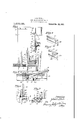
- FIG. 1 is a fragmentary top plan view of the saw-table provided with a work holding device embodying my invention
- Figure 2 is a fragmentary top plan view showing the pressure-bar and a plurality of type-bar slugs arranged for the production of extremely short slug sections;
- Figure 3 is a fragmentary vertical section on the line 33 of Figure 2;
- Figure 4 is a fragmentary perspective view of the slug contacting end of the pressure-bar
- Figure 5 is a similar view of a modified form of the bar.
- Figure 6 is a fragmentary vertical sectional view on the line 6-6 of Figure 1, particularly illustrating the means which I employ for forcing the tact with theslugs.
- 1 represents a saw-table having a circular saw 2 and a movable saw-table or top 3 which is movable in guides 4 past the saw for cutting slugs 5 to a desired length.
- a transverse fixed abutment 6 against which the plurality of slugs 5 are arranged, and in connection with this abutment there is provided a transversely movable abutment 7 which extends at ri ht angles to the abutment 6 and is ad-' jus ta le longitudinally of the abutment 6 to position the slugs 5 so that the saw will cut them to the desired length.
- the abutment 7 is movable by means of a screw worm 8 intermeshingiwith a screw rack 9 provided on the abutment 6.
- I PI'OVKlBWl holding device 10 adapted to be removably secured upon the saw-table top 3 by screws 11, theholding device being provided with lugs 12 for receiving these screws.
- the holding device 10 comprises an elongated frame 13 having side walls 14 and a central longitudinal slot 15 in its upper side. It is provided with a screw rack 16 underneath its top and I provide a worm 17 for engaging this rack.
- the dog is mounted on the lower end of anoperating handle 18 which rotatably mounted ina block 19 pivotally mounted on a pin 20 carried by a sliding pressure-bar 21. This bar 21 is guided in the holder 10 and is adapted to be. moved longitudinally of the holder frame by means of the handle member 18. By means of the handle member 18 the block 19 and worm 17 are rotated on the pin 20 to cause the worm to engage and disengage the screw rack.
- the worm is disengaged from the screw rack the pressure-bar 21 can bemoved freely longitudinally of the holder to position it against the slugs to be held and when it is positioned against the slugs a downward movement of the handle 18 lifts the worm 17 into the rack and then by rotatingthe handle the worm 17 is rotated and the bar 21 is forced against the slugs with considerable force.
- lVhen thus pressed against the slugs the bar locked against freeing theslugs by the worm 17 and rack 16.
- the bar 21 carries a block 22 arranged to the loweror inner end of the worm 17 and against which the worm rests to hold the handle 18 against longitudinal movement in the block .19.
- This block 22 carries a vertical projection 23 which eittends up through the slot 15 and receives a screw 24: by which atransversebinder strap 25 is secured in position.
- This strap 25 ertends transversely across. the two sidewalls of the holder and prevents these side walls springing upwardly by reason of the tightening of the worm 17, when clamping slugs.
- the pressure-bar 21 is a thin bar placed on edge and its slug contacting end 26 is cut square and adapted to be pressed flat against the slugs to hold them pressed against the abutment 6.
- Thebar is thin so that the abutment 7 may be placed as close as possible to the plane of the saw for positioning slugs to produce very short slugs as best indicated in Figure 2.
- the slugs 5 which are represented'as being the well known linotype slugs are each provided with a plurality of vertical fitting ribs 27, which ribs are spaced substantially of an inch apart longitudinally of the slug and the body of the pressure-bar 21 is preferably only about 1- of an. inch thick. Consequently when cutting very short slugs the pressure bar is apt to press against the slugs between the fitting ribs 27 and the abutment '7 or directly over the fitting ribs as shown in Figure 2, in which position the slugs are apt to become loosened by the sawing operation and fly or jump out of their clamping position.
- the abutment member 7 is provided with a vertical flange 29'against which the inner ends of the slugs are positioned to align the slugs for sawing.
- This flange 2. does not reach to the top of the slugs, its upper edge 30 being arranged below the lower edge off the projection 28 so that the n'ojection 28 can pass freely over the flange 29 when the several parts are arranged for cutting extremely short slugs as shown in Figures 2 and 3.
- the projection 28 widens the slug contacting end of the bar 21 suiiiciently so that it is as wide or wider than'the distance from one rib to the next, and it is preferably about once and a half as wide as the spacing of the ribs and it performs its function of assisting in firmly holding the slugs 5 whether long or short slugs are being cut. It does not interfere with the positioning of the abutment 7 when extremely short slugs are desired. In other words, the projection 2S-does not have to be removed from the bar 21 for the purpose of cutting extremely short slugs as would be the case it the projection 28 extended below the top of the flange 29.
- a device for sawing linotype slugs a circular saw, a table movable past the saw for cutting the slugs, a transverse fixed abutment on the i ment associated with the fixed abutment ble against which theslugs held, a transversely movable abut and against which the ends of the slugs are aligned, a relatively thin pressure-bar set on edge, and means for pressing it endwise towards the fixed'abutment, to clamp a plurality of slugs against the abutment, a transversely extending projection on the slug contacting end of the bar for widening the contact between the bar and thetype slugs, the movable abutment being of less height than the pressure-bar, and said projection being arranged to pass freely over the movable abutment when the abutment adjusted close to the pressure-bar, substantially as described.
- a saw, type slug support movable past the saw for cutting slugs having transverse fitting ribs spaced substantially uniformly longitudinally of the slugs, a fixed abutment on the support against Whichthe slugs are held, a movable abutment for aligning the ends of the slugs, a relatively thin pressurebar set on edge and means for forcing the pressure-bar endwise against the slugs, an integral transversely extending projection on the slug contacting end of the pressurebar or less height thanthe height of said bar to make the contacting surface wider than the spacing of the fitting ribs on the slugs, substantially as described.
- a device for sawing linctype slugs a circular saw, a table movable pastthe saw for cutting the slugs, a transverse fixed abutment on the table against which the slugs are held, a: transversely movable abutment associated with the fixed abutment and against which the ends of the slugs are aligned, a relatively thin pressure-bar set on edge, and means for pressing it endwise towards the' fixed abutment, to clamp a plurality of slugs against the abutment, a transversely xtending projection on' the slug contacting end of the bar for widening the contact between the bar and the slugs, the pressure bar being of greater-vertical width than the slug contacting surface 01" the movable abutment, and said pro jection adapted'to project beyond said contacting surface of the movable abutment whenthe abutment is moved into close proximity to the bar, as and for the purpose
Landscapes
- Sawing (AREA)
Description
J. w. STEELE.
WORK HOLDER FOR SAW TABLES.
APPLICATION FILED MAR. 26, 1920.
1 ,41 O, 1 85 Patented Mar. 21, 1922.
MIL
UNITED STATES JOHN W. STEELE, OF CHICAGO, ILLINOIS WORK HOLDER FOR SAW TABLES.
Specification of Letters Patent.
Patented Mar. 21, 1922.
Application filed March 26, 1920. Serial No. 368,902.
T 0 all w 710m it may concern:
Be it known that I, JOHN IV. STEELE, a citizen of the United States, and resident of Chicago, in the county of Cook and State of Illinois, have invented certain new and useful Improvements in Work Holders for Saw Tables, of which the following is a specification.
My invention relates to improvements in work holding devices for saw tables and has special reference to devices for holding linotype or printing slugs while they are being cut or sawed to a desired lengt Type bars or slugs, especially those com-- monly known as linotype slugs, are provided with vertical fitting ribs spaced longitudinally of the slugs and it is found that with the form of clamping bars in common use on devices of this character these fitting ribs prevent the rigid clamping of several bars between the abutment and the clamping bar, particularly when it is desired to produce extremely short type bars, such for instance, as two or three ems in length.
In fact the danger of the displacement of the type bars when held by the ordinary pressure device and when it is desired to produce very short type bars, is so great that the production of short type-bars is seldom attempted without undesired results. These results may be merely the loosening and throwing about of the type-bars being cut, but frequently serious accidents such as the cutting off or maiming of the operators fingers occur, well the m'utilating of the type-bars.
By means of my improvement I am en abled to produce the shortest length slugs desired even though such slugs carry only one of the vertical ribs and with substantially no possibility of the accidental displacement of the slugs in the cutting operation.
My improved work holder comprises a fixed abutment and a thin pressure-bar set on edge and means for forcing the bar endwise towards the abutment to clamp a plurality of type-bars against the abutment while they are being sawed. The fixed abutment is associated with a movable abutment adapted to be set from and toward the plane of the saw and against which the desired ends of the slugs are placed for alignment. Means are provided for forcing and locking the pressure-bar against the pile of slugs for the sawing operation, and I provide a fixed right-angle projection on the free end of the pressure-bar for contact with the slugs, which serves to spread out transversely of the pressure bar and longitudinally of the slugs, the contact of the end of the bar with the slugs. This wide contacting surface prevents the spreading of the slugs and serves to hold them tightly clamped in place against the fixed abutment. V
I do not extend this lateral projection from the top to the bottom of the pressurebar, as it would then interfere with the movable abutment when the very short slugs are desired but I so arrange it that themovable abutment can be moved substantially into contact with the adjacent side of the pressure-bar at which times the projection overlaps or extends over the movable abutment.
My invention involves more than the mere widening or thickening of the work contactmg end of the pressure-bar. It comprises the provision of such an enabling projection on the bar and so arranged with reference to the movable abutment that the bar or projection does not have to be changed or al tered for cutting slugs of extreme shortness or longer.
My invention will be more readily understood by reference to the accompanying drawings forming part of this specification, and in which Figure 1 is a fragmentary top plan view of the saw-table provided with a work holding device embodying my invention;
Figure 2 is a fragmentary top plan view showing the pressure-bar and a plurality of type-bar slugs arranged for the production of extremely short slug sections;
Figure 3 is a fragmentary vertical section on the line 33 of Figure 2;
Figure 4 is a fragmentary perspective view of the slug contacting end of the pressure-bar;
Figure 5 is a similar view of a modified form of the bar; and
Figure 6 is a fragmentary vertical sectional view on the line 6-6 of Figure 1, particularly illustrating the means which I employ for forcing the tact with theslugs.
In said drawings:
1 represents a saw-table having a circular saw 2 and a movable saw-table or top 3 which is movable in guides 4 past the saw for cutting slugs 5 to a desired length. On
pressure bar into conthe movable top 3 is arranged a transverse fixed abutment 6 against which the plurality of slugs 5 are arranged, and in connection with this abutment there is provided a transversely movable abutment 7 which extends at ri ht angles to the abutment 6 and is ad-' jus ta le longitudinally of the abutment 6 to position the slugs 5 so that the saw will cut them to the desired length. The abutment 7 is movable by means of a screw worm 8 intermeshingiwith a screw rack 9 provided on the abutment 6.
For holdin the slu s against the abutment 6 I PI'OVKlBWl holding device 10 adapted to be removably secured upon the saw-table top 3 by screws 11, theholding device being provided with lugs 12 for receiving these screws. 1
The holding device 10 comprises an elongated frame 13 having side walls 14 and a central longitudinal slot 15 in its upper side. It is provided with a screw rack 16 underneath its top and I provide a worm 17 for engaging this rack. The dog is mounted on the lower end of anoperating handle 18 which rotatably mounted ina block 19 pivotally mounted on a pin 20 carried by a sliding pressure-bar 21. This bar 21 is guided in the holder 10 and is adapted to be. moved longitudinally of the holder frame by means of the handle member 18. By means of the handle member 18 the block 19 and worm 17 are rotated on the pin 20 to cause the worm to engage and disengage the screw rack. lVhen the worm is disengaged from the screw rack the pressure-bar 21 can bemoved freely longitudinally of the holder to position it against the slugs to be held and when it is positioned against the slugs a downward movement of the handle 18 lifts the worm 17 into the rack and then by rotatingthe handle the worm 17 is rotated and the bar 21 is forced against the slugs with considerable force. lVhen thus pressed against the slugs the bar locked against freeing theslugs by the worm 17 and rack 16. The bar 21 carries a block 22 arranged to the loweror inner end of the worm 17 and against which the worm rests to hold the handle 18 against longitudinal movement in the block .19. This block 22 carries a vertical projection 23 which eittends up through the slot 15 and receives a screw 24: by which atransversebinder strap 25 is secured in position. This strap 25ertends transversely across. the two sidewalls of the holder and prevents these side walls springing upwardly by reason of the tightening of the worm 17, when clamping slugs.
The pressure-bar 21 is a thin bar placed on edge and its slug contacting end 26 is cut square and adapted to be pressed flat against the slugs to hold them pressed against the abutment 6. Thebar is thin so that the abutment 7 may be placed as close as possible to the plane of the saw for positioning slugs to produce very short slugs as best indicated in Figure 2. v
The slugs 5 which are represented'as being the well known linotype slugs are each provided with a plurality of vertical fitting ribs 27, which ribs are spaced substantially of an inch apart longitudinally of the slug and the body of the pressure-bar 21 is preferably only about 1- of an. inch thick. Consequently when cutting very short slugs the pressure bar is apt to press against the slugs between the fitting ribs 27 and the abutment '7 or directly over the fitting ribs as shown in Figure 2, in which position the slugs are apt to become loosened by the sawing operation and fly or jump out of their clamping position. In fact it is diflis cult to properly clamp these slugs for ,producing short length slugs by means of thenarrow bar 21. At othertimes the narrow end of the pressure-bar presses against the free ends of the slugs beyond the outmost ribs, under which condition the inner ends of the slugs are apt to spread out and loosen the slugs.
For the purpose of holding the slugs firmly clamped whether they are positioned to produce long or short portions of the slugs I provide a transversely extending projection 28 on the slug contacting end 26 of the bar 21 having its forward face flush with the end 6 and extending on the side of the bar 21 in a direction away from the saw so that the bar itself can be placed closeto the plane of the saw as best shown in Figure 1 without danger oi? the projection 28 rontacting with the saw.
I arrange the projection 28 at the upper edge ot' the pressure bar 21 and relatively narrow vertically, but at a height where it will contact with the slugs 5 as best shown in Figure 8. The abutment member 7 is provided with a vertical flange 29'against which the inner ends of the slugs are positioned to align the slugs for sawing. This flange 2.) does not reach to the top of the slugs, its upper edge 30 being arranged below the lower edge off the projection 28 so that the n'ojection 28 can pass freely over the flange 29 when the several parts are arranged for cutting extremely short slugs as shown in Figures 2 and 3. The projection 28'widens the slug contacting end of the bar 21 suiiiciently so that it is as wide or wider than'the distance from one rib to the next, and it is preferably about once and a half as wide as the spacing of the ribs and it performs its function of assisting in firmly holding the slugs 5 whether long or short slugs are being cut. It does not interfere with the positioning of the abutment 7 when extremely short slugs are desired. In other words, the projection 2S-does not have to be removed from the bar 21 for the purpose of cutting extremely short slugs as would be the case it the projection 28 extended below the top of the flange 29.
ll hile I have shown the projection 28 in Fig. l as being made integral with the bar 21 it will be obvious that the projection can be a separate piece of metal secured permanently upon the. bar 21. as illustrated in Figure 5 wherein I have shown a block 31 of similar vertical dimensions and positioned similarly to the projection :28 and permanently secured to the bar 21 by means of rivets 32.
As it is obvious that many modifications oi my invention will readily suggest themselves to one skilled in the art, I do not limit or routine my invention to the specific structures herein shown and described.
I claim:
1. In a device or the kind described, the combination with a circular saw, a table movable past the saw for cutting type-bars, a transverse fixed abutment on the table against which the type-bars are held, a relatively thin pressure-bar set on edge and means for pressing it endwise towards the fixed abutment to hold a plurality of typebars against the abutment, the bar having an integral projection on its type-bar contacting end extending on the side opposite to the saw and arranged near one lateral edge of the bar, said projection being adapted to provide wide bearing surface of the ba on the slugs, substantially as described.
In a device of the kind described, a circular saw, a table movable past the saw for cutting type=bars, a transverse fixed abutment on the table against which the type-bars ure held, a relatively thin pressure-bar set on edge and means for pressing it endwise towards the fixed abutment to clamp a plurality of type-bars against the abutment, a transversely movable abutment for aligning the ends of the type-bars, a projection on the end of the pressure-bar tor widening the contact between the pressure bar and the type-bars, the projection and the movable abutment being arranged to freely overlap when the abutment is adj usted close to the adjacent side of the pres surebar. substantially as described.
3. In a device for sawing linotype slugs, a circular saw, a table movable past the saw for cutting the slugs, a transverse fixed abutment on the i ment associated with the fixed abutment ble against which theslugs held, a transversely movable abut and against which the ends of the slugs are aligned, a relatively thin pressure-bar set on edge, and means for pressing it endwise towards the fixed'abutment, to clamp a plurality of slugs against the abutment, a transversely extending projection on the slug contacting end of the bar for widening the contact between the bar and thetype slugs, the movable abutment being of less height than the pressure-bar, and said projection being arranged to pass freely over the movable abutment when the abutment adjusted close to the pressure-bar, substantially as described.
4. In a device of the kind described, a saw, type slug support movable past the saw for cutting slugs having transverse fitting ribs spaced substantially uniformly longitudinally of the slugs, a fixed abutment on the support against Whichthe slugs are held, a movable abutment for aligning the ends of the slugs, a relatively thin pressurebar set on edge and means for forcing the pressure-bar endwise against the slugs, an integral transversely extending projection on the slug contacting end of the pressurebar or less height thanthe height of said bar to make the contacting surface wider than the spacing of the fitting ribs on the slugs, substantially as described.
5. In a device for sawing linctype slugs, a circular saw, a table movable pastthe saw for cutting the slugs, a transverse fixed abutment on the table against which the slugs are held, a: transversely movable abutment associated with the fixed abutment and against which the ends of the slugs are aligned, a relatively thin pressure-bar set on edge, and means for pressing it endwise towards the' fixed abutment, to clamp a plurality of slugs against the abutment, a transversely xtending projection on' the slug contacting end of the bar for widening the contact between the bar and the slugs, the pressure bar being of greater-vertical width than the slug contacting surface 01" the movable abutment, and said pro jection adapted'to project beyond said contacting surface of the movable abutment whenthe abutment is moved into close proximity to the bar, as and for the purpose specified.
Signed at Chicago, Illinois, this 20th day of #larch, 1920.
JOHN IV. STEELE.
WVitness:
T, D. BUTLER.
Priority Applications (1)
| Application Number | Priority Date | Filing Date | Title |
|---|---|---|---|
| US36890220 US1410135A (en) | 1920-03-26 | 1920-03-26 | Work holder for saw tables |
Applications Claiming Priority (1)
| Application Number | Priority Date | Filing Date | Title |
|---|---|---|---|
| US36890220 US1410135A (en) | 1920-03-26 | 1920-03-26 | Work holder for saw tables |
Publications (1)
| Publication Number | Publication Date |
|---|---|
| US1410135A true US1410135A (en) | 1922-03-21 |
Family
ID=23453233
Family Applications (1)
| Application Number | Title | Priority Date | Filing Date |
|---|---|---|---|
| US36890220 Expired - Lifetime US1410135A (en) | 1920-03-26 | 1920-03-26 | Work holder for saw tables |
Country Status (1)
| Country | Link |
|---|---|
| US (1) | US1410135A (en) |
-
1920
- 1920-03-26 US US36890220 patent/US1410135A/en not_active Expired - Lifetime
Similar Documents
| Publication | Publication Date | Title |
|---|---|---|
| US2898854A (en) | Printing plate and cylinder | |
| US1410135A (en) | Work holder for saw tables | |
| US3185470A (en) | Universal work clamping fixtures for machine tools | |
| US3334894A (en) | Guides for paper magazine | |
| US2756675A (en) | Printing plate clamping device | |
| US2677426A (en) | Multiple piece template for punch presses | |
| US2084518A (en) | Perforator for printing presses | |
| US1857214A (en) | Web positioning mechanism | |
| US3124180A (en) | Mitering gage for work tables | |
| US1389320A (en) | Clamp for cloth-machines | |
| US2137113A (en) | Work clamp | |
| US3149564A (en) | Attachments for printing devices | |
| US1044861A (en) | Punch-press. | |
| US698343A (en) | Gage-pin for job-printing presses. | |
| US3334893A (en) | Guides for paper magazine | |
| US788962A (en) | Saw-clamp. | |
| US848363A (en) | Adjustable cross-bar for printers' chases. | |
| US1343220A (en) | Holding device for printing-plates | |
| US1069927A (en) | Line setting and casting machine. | |
| US821293A (en) | Device for dressing band-saws. | |
| US827982A (en) | Printing-stamp. | |
| US462799A (en) | isaac a | |
| US506433A (en) | Miter-saw | |
| US1364103A (en) | Paper take-up for typewriting-machines | |
| US1963585A (en) | Lead for printing presses |