US1394271A - Torpedo - Google Patents
Torpedo Download PDFInfo
- Publication number
- US1394271A US1394271A US456009A US45600921A US1394271A US 1394271 A US1394271 A US 1394271A US 456009 A US456009 A US 456009A US 45600921 A US45600921 A US 45600921A US 1394271 A US1394271 A US 1394271A
- Authority
- US
- United States
- Prior art keywords
- valve
- torpedo
- spring
- exhaust
- cylinder
- Prior art date
- Legal status (The legal status is an assumption and is not a legal conclusion. Google has not performed a legal analysis and makes no representation as to the accuracy of the status listed.)
- Expired - Lifetime
Links
- 239000007789 gas Substances 0.000 description 4
- 241000251729 Elasmobranchii Species 0.000 description 2
- 241000220010 Rhode Species 0.000 description 2
- XLYOFNOQVPJJNP-UHFFFAOYSA-N water Substances O XLYOFNOQVPJJNP-UHFFFAOYSA-N 0.000 description 2
- 230000006978 adaptation Effects 0.000 description 1
- 230000004075 alteration Effects 0.000 description 1
- 238000010276 construction Methods 0.000 description 1
- 239000000463 material Substances 0.000 description 1
- 230000004048 modification Effects 0.000 description 1
- 238000012986 modification Methods 0.000 description 1
- 229920000136 polysorbate Polymers 0.000 description 1
Images

Classifications
-
- F—MECHANICAL ENGINEERING; LIGHTING; HEATING; WEAPONS; BLASTING
- F42—AMMUNITION; BLASTING
- F42B—EXPLOSIVE CHARGES, e.g. FOR BLASTING, FIREWORKS, AMMUNITION
- F42B19/00—Marine torpedoes, e.g. launched by surface vessels or submarines; Sea mines having self-propulsion means
- F42B19/12—Propulsion specially adapted for torpedoes
Definitions
- This invention re ates to improvements in torpedoes and more particularly to an attachment associated with the exhaust valve whereby the operation of this valve becomes more reliable and efficient in use.
- One of the objects of the present invention is, therefore, to provide a simple and practical attachment adapted t0 be associated with the valve mechanism whereby the life of the spring is greatly increased by reason of the fact that the heat radiated from the exhaust pipe is absorbed by an adjacent member and deflected therefrom into the 'surrounding atmosphere.
- a further object is to provide a deflector of the above general character which may be inexpensively manufactured and installed in the mechanism now in general use without material modification or alteration of the parts or increasing materially the weight of the tor edo.
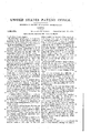
- valve 3 carried on the end of the arm 4 pi'v- Y oted at 5 and actuated by means of intervening link mechanism 6.
- This link mechanism is connected to a plunger 7 operating within a cylindrical casing or cylinder 8 and closed at its end by nut 10.
- a spiral coiled spring l1 Interposed between the plunger or piston head 7 and the base of the chamber constituting the cylinder 8 is a spiral coiled spring l1 normally urging the piston head 7 toward the left thereby keeping the valve 8 closed under normal conditions.
- the pressure of the exhaust gases are sufficient to overcome the tension of this spring and allow the gases to escape.
- a shield 12 of general cylindrical shape is positioned about the cylinder 8 and provided on its interior with a plurality of clips 13 adapted to be engaged by the nut 10 thereby to force the reduced flanged end 14 into engagement with the supporting end wall of the after-body.
- the invention is of simple and practical construction and may be inexpensively manufactured, assembled and installed.
- spring actuated piston connected with said body at one end and clips interposed bevalve to normally maintain the same in tween the cylinder and the said means near closed position, a cylinder surrounding said the opposite end. 10 spring and piston, means inclosing said eyl- Signed at Newport, Rhode Island, this inder for absorbing the heat radiated from 15th day of February, 1921.
Landscapes
- Engineering & Computer Science (AREA)
- Chemical & Material Sciences (AREA)
- Combustion & Propulsion (AREA)
- General Engineering & Computer Science (AREA)
- Exhaust Silencers (AREA)
Description
E. S. R. BRANDT.
y ToRPEno. APlLlCATlON FILED MAR. 26, 192|- 1,394,271, Patented' 00u18, 1921.
UNITED ST'EES Param" crates.
EDMUND S. R. BRANDT, OF NEWPORT, RHODE ISLAND.
TORPEDO.
Application filed March 26, 1921.
To all whom t may conce/m.'
Be it known that I, EDMUND S. R. BRANDT, a citizen of the United States, residing at Newport, Rhode Island, have invented new and useful Improvements in Torpedoes, of which the followin is a specification.
This invention re ates to improvements in torpedoes and more particularly to an attachment associated with the exhaust valve whereby the operation of this valve becomes more reliable and efficient in use.
By way of explanation it might be stated Y that the exhaust gases from a torpedo pass through longitudinally disposed pipes in the after-body and exhaust into the water near the propellers at the tail. These exhaust pipes are closed by an automatically operating valve for the purpose of preventing the ingress of water, if for any reason the source of power 0f the torpedo stops its operation. The valve is usually spring controlled but by reason of the heat radiated from the exhaust pipe the elasticity of the spring becomes more or less annealed or weakened thereby losing its elasticity and preventing a proper closing of the valve.
One of the objects of the present invention is, therefore, to provide a simple and practical attachment adapted t0 be associated with the valve mechanism whereby the life of the spring is greatly increased by reason of the fact that the heat radiated from the exhaust pipe is absorbed by an adjacent member and deflected therefrom into the 'surrounding atmosphere.
A further object is to provide a deflector of the above general character which may be inexpensively manufactured and installed in the mechanism now in general use without material modification or alteration of the parts or increasing materially the weight of the tor edo.
Other o jects will be in part obvious and in part hereinafter pointed out in connection with the accompanying sheets of drawings forming part of this disclosure wherein is shown in longitudinal section one of the exhaust pipes and the associated valve and operating mechanism.
Referring to this drawing in detail, 1, denotes the usual exhaust pipe terminating at a member 2 in the tail of the torpedo, which member forms a valve seat for the disk Specification of Letters Patent.
Patented Oct. 18, 1921.
serial No. 456,009.
Heretofore this cylinder 8 being so closely adjacent the gas pipe absorbed a great deal of heat radiated therefrom and in time so seriously weakend the elasticity of the spring 11 that it was necessary to replace the same in. order to insure a proper closing of the valve.
In order to overcome this difficulty, a shield 12 of general cylindrical shape is positioned about the cylinder 8 and provided on its interior with a plurality of clips 13 adapted to be engaged by the nut 10 thereby to force the reduced flanged end 14 into engagement with the supporting end wall of the after-body.
It will thus be seen that the intense heat radiated from the exhaust pipe will be absorbed by this deiiector 12 and distributed thereby materially reducing the heat transmitted eventually to the spring 11.
The invention is of simple and practical construction and may be inexpensively manufactured, assembled and installed.
Without further analysis, the foregoing will so fully reveal the gist of this invention that others can by applying current knowledge readily adapt it for various applications without omitting certain features, that, from the standpoint of the prior art, fairly constitute essential characteristics of the generic or specific aspects of this invention, and, therefore, such adaptations should and are intended to be comprehended withiny the meaning and range of equivalency of the following claim.
What I claim is In a torpedo, in combination, an exhaust pipe, a valve normally closing Said pipe, a
spring actuated piston connected with said body at one end and clips interposed bevalve to normally maintain the same in tween the cylinder and the said means near closed position, a cylinder surrounding said the opposite end. 10 spring and piston, means inclosing said eyl- Signed at Newport, Rhode Island, this inder for absorbing the heat radiated from 15th day of February, 1921.
the exhaust pipe, saidV means being supa .i
ported adjacent the end Wall of the after-V E. S. R. BRANDT,
Priority Applications (1)
| Application Number | Priority Date | Filing Date | Title |
|---|---|---|---|
| US456009A US1394271A (en) | 1921-03-26 | 1921-03-26 | Torpedo |
Applications Claiming Priority (1)
| Application Number | Priority Date | Filing Date | Title |
|---|---|---|---|
| US456009A US1394271A (en) | 1921-03-26 | 1921-03-26 | Torpedo |
Publications (1)
| Publication Number | Publication Date |
|---|---|
| US1394271A true US1394271A (en) | 1921-10-18 |
Family
ID=23811074
Family Applications (1)
| Application Number | Title | Priority Date | Filing Date |
|---|---|---|---|
| US456009A Expired - Lifetime US1394271A (en) | 1921-03-26 | 1921-03-26 | Torpedo |
Country Status (1)
| Country | Link |
|---|---|
| US (1) | US1394271A (en) |
-
1921
- 1921-03-26 US US456009A patent/US1394271A/en not_active Expired - Lifetime
Similar Documents
| Publication | Publication Date | Title |
|---|---|---|
| US1394271A (en) | Torpedo | |
| US1877118A (en) | Gun | |
| US1844865A (en) | Electrically controlled percussion firing mechanism | |
| US2493644A (en) | Pressure releasing device | |
| US1281274A (en) | Tire-signal. | |
| US1868165A (en) | Tire valve | |
| US1468492A (en) | Cut-out for mufflers of explosive engines | |
| GB293236A (en) | Improvements in exhaust silencing and cut-out devices for motorcycles and the like | |
| US1781026A (en) | Fire-extinguishing system | |
| US652742A (en) | Device for preventing reports of guns. | |
| US1994559A (en) | Signal or musical instrument | |
| US516236A (en) | Jakob stahel | |
| US1389190A (en) | Torpedo | |
| US1080154A (en) | Silencer for firearms. | |
| US1494694A (en) | John b | |
| US832803A (en) | Air-cooler for motor-cylinders. | |
| US1950847A (en) | Check valve | |
| US1372874A (en) | Valve mechanism | |
| US1528489A (en) | Safety tube | |
| US1597729A (en) | Safety device for preventing passage of flame | |
| US1544445A (en) | Gas generator | |
| US1387591A (en) | Blowpipe-burner | |
| US1346791A (en) | Thermo safety-valve | |
| US2006671A (en) | Power developing and distributing means | |
| US1326764A (en) | Tibe-pump |